BHCB63640BH - Fridge Freezer BEKO - Free user manual and instructions
Find the device manual for free BHCB63640BH BEKO in PDF.
| Product type | Range hood |
| Brand | BEKO |
| Model | BHCB63640BH |
| Supply voltage | 220-240 V ~ 50 Hz |
| Motor power | 210 W |
| Maximum airflow rate | 616 m³/h |
| Number of speeds | 3 |
| Lighting | LED, 2 x 3 W |
| Grease filter | Aluminum, washable |
| Charcoal filter | Active, replace every 3 months |
| Insulation class | Class I |
| Air outlet diameter | 120/150 mm |
| Minimum distance to hob | 65 cm |
| Mounting | Wall-mounted |
| Operating mode | Extraction or recirculation with charcoal filter |
| Grease filter maintenance | Monthly cleaning |
| Charcoal filter maintenance | Quarterly replacement |
| Included accessories | Ducts, wall plugs, screws, air deflector, non-return valve |
| Lighting power | 3 W per lamp |
| Bulb type | LED GZ10 |
Frequently Asked Questions - BHCB63640BH BEKO
User questions about BHCB63640BH BEKO
0 question about this device. Answer the ones you know or ask your own.
Ask a new question about this device
Download the instructions for your Fridge Freezer in PDF format for free! Find your manual BHCB63640BH - BEKO and take your electronic device back in hand. On this page are published all the documents necessary for the use of your device. BHCB63640BH by BEKO.
USER MANUAL BHCB63640BH BEKO
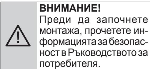
Please read this guide first!
Dear Customer,
Thank you for choosing a BEKO product. We would like you to achieve the optimal efficiency from this high quality product which has been manufactured with state of the art technology. Please make sure you read and understand this guide and supplementary documentation fully before use and keep it as a reference. Include this guide with the unit if you hand it over to someone else. Observe all warnings and information herein and follow the instructions.
Keep in mind that this user guide may apply to several product models. The guide clearly indicates any variations of different models.
Symbols and their meanings
These symbols are used throughout this guide:
| i | Important information and recommendations regarding the use of the appliance. |
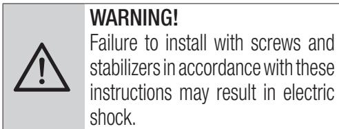
| ! | CAUTION:Warnings on personal injury or property damage. |
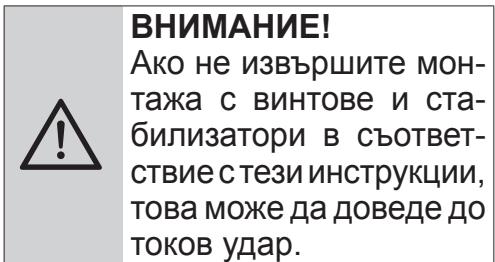
| 4 | Electric shock warning, |
| Risk of fire warning. |

This product has been manufactured at modern facilities respectful to the environment without harming nature.
CONTENTS
| ENGLISH | 04-16 |
| DEUTSCH | 17-33 |
| FRANÇAIS | 34-49 |
| ESPAÑOL | 50-67 |
| Българский | 68-85 |
| NEDERLANDS | 86-102 |
| PORTUGUES | 103-119 |
1 Important Safety and Environmental Instructions
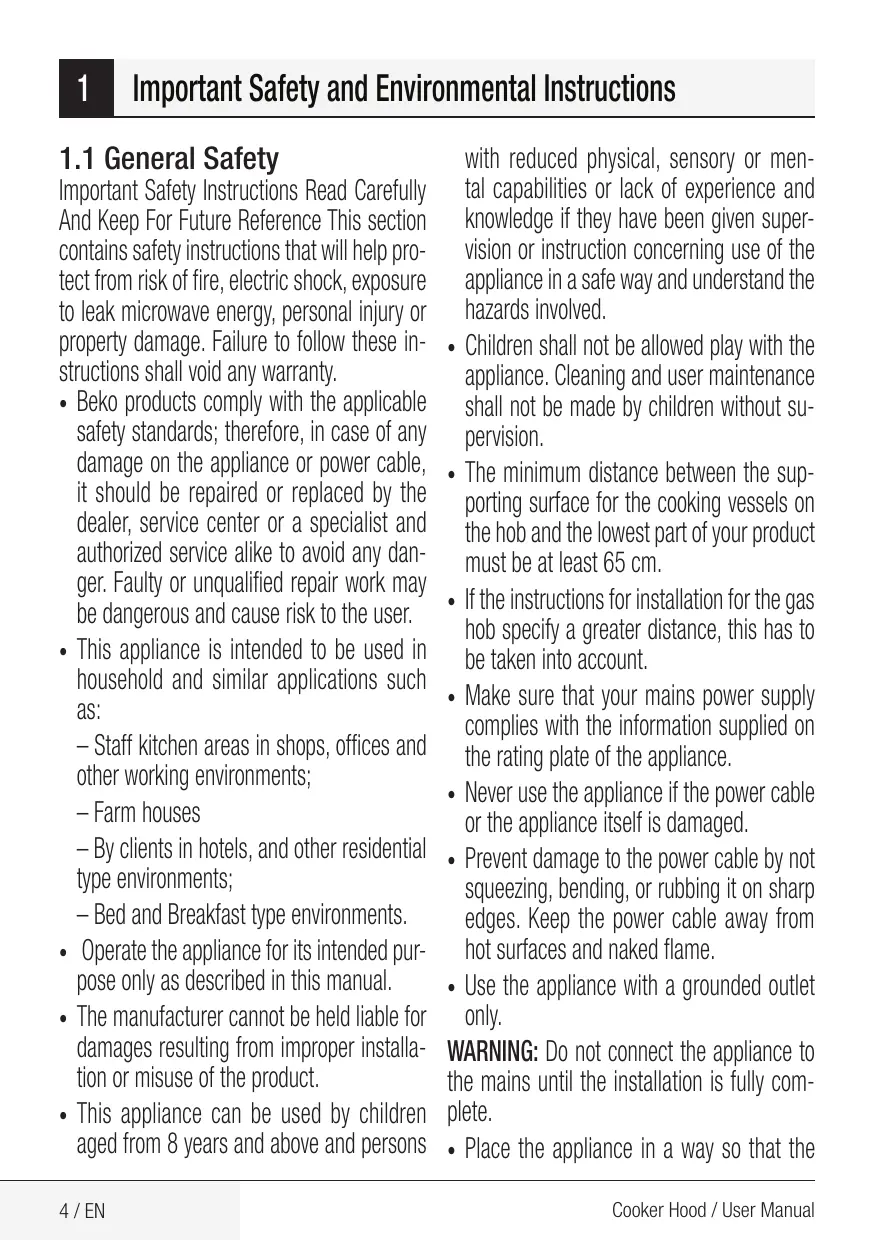
1.1 General Safety
Important Safety Instructions Read Carefully And Keep For Future Reference This section contains safety instructions that will help protect from risk of fire, electric shock, exposure to leak microwave energy, personal injury or property damage. Failure to follow these instructions shall void any warranty.
- Beko products comply with the applicable safety standards; therefore, in case of any damage on the appliance or power cable, it should be repaired or replaced by the dealer, service center or a specialist and authorized service alike to avoid any danger. Faulty or unqualified repair work may be dangerous and cause risk to the user.
-
This appliance is intended to be used in household and similar applications such as:
-
Staff kitchen areas in shops, offices and other working environments;
- Farm houses
- By clients in hotels, and other residential type environments;
-
Bed and Breakfast type environments.
-
Operate the appliance for its intended purpose only as described in this manual.
- The manufacturer cannot be held liable for damages resulting from improper installation or misuse of the product.
- This appliance can be used by children aged from 8 years and above and persons
with reduced physical, sensory or mental capabilities or lack of experience and knowledge if they have been given supervision or instruction concerning use of the appliance in a safe way and understand the hazards involved.
- Children shall not be allowed play with the appliance. Cleaning and user maintenance shall not be made by children without supervision.
- The minimum distance between the supporting surface for the cooking vessels on the hob and the lowest part of your product must be at least 65~cm .
- If the instructions for installation for the gas hob specify a greater distance, this has to be taken into account.
- Make sure that your mains power supply complies with the information supplied on the rating plate of the appliance.
- Never use the appliance if the power cable or the appliance itself is damaged.
- Prevent damage to the power cable by not squeezing, bending, or rubbing it on sharp edges. Keep the power cable away from hot surfaces and naked flame.
- Use the appliance with a grounded outlet only.
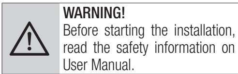
WARNING: Do not connect the appliance to the mains until the installation is fully complete.
- Place the appliance in a way so that the
plug is always accessible.
- Do not touch the lamps if they have operated for a long time. They can burn your hands since they will be hot.
- Follow the regulations set out by competent authorities on discharge of the exhaust air (this warning is not applicable for use without Chimney).
- Operate your appliance after putting a pot, pan etc. on the hob. Otherwise, high heat may cause deformation in some parts of your product.
- Turn off the hob before taking the pot, pan etc. from it.
- Do not leave hot oil on the hob. Pans with hot oil may cause self combustion.
- Pay attention to your curtains and covers since oil may catch fire while cooking food such as fries.
- Grease filter must be replaced at least monthly. Carbon filter must be replaced at least every 3 months.
- Product shall be cleaned accordance with user manual. If cleaning was not carried out in accordance with user manual, there may be fire risk.
- Do not use non-fire-resistant filtering materials instead of the current filter.
- Only use the original parts or parts recommended by the manufacturer.
- Do not operate the product without the fil
ter and do not remove the filters while the product is running.
- In the event of be started any flame, de-energize your product and cooking appliances.
- In the event of be started any flame, cover the flame and never use water to extinguish.
- Unplug the appliance before each cleaning and when the appliance is not in use.
- The negative pressure in the environment should not exceed 4 Pa (4 x 10 bar) while the hood for electric hob and appliances running on another type of energy but electricity operate simultaneously.
- In the environment where the appliance is being used, the exhaust of devices running on fuel oil or gas, such as room heater must be absolutely isolated or device must be hermetical type.
- When connecting the Chimney, use pipes with a diameter of 120 or 150~mm . Pipe connection must be as short as possible and have as few elbows as possible.
Danger of choking! Keep all the packaging materials away from children.
CAUTION: Accessible parts may become hot when used with cooking appliances.
- The product outlet must not be connected to air channels that include other smoke.
- The ventilation in the room may be insufficient when the hood for electric hob is
used simultaneously with the devices operating on gas or other fuels (this may not apply to appliances that only discharge the air back into the room).
- Objects placed on the product may fall. Do not place any objects on the product.
- Do not flambe under the your product.
WARNING: Before installing the Hood, remove the protective films.
- Never leave high naked flames under the hood when it is in operation
- Deep fat fryers must be continuously monitored during use: overheated oil can burst into flames.
1.2 Compliance with the WEEE Directive and Disposing of the Waste Product:
This product complies with EU WEEE Directive (2012/19/EU). This product bears a classification
symbol for waste electrical and electronic equipment (WEEE).
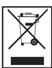
This symbol indicates that this product shall not be disposed with other household wastes at the end of its service life. Used device must
be returned to official collection point for recycling of electrical and electronic devices. To find these collection systems please contact to your local authorities or retailer where the product was purchased. Each household performs important role
in recovering and recycling of old appliance. Appropriate disposal of used appliance helps prevent potential negative consequences for the environment and human health.
1.3 Compliance with RoHS Directive
The product you have purchased complies with EU RoHS Directive (2011/65/EU). It does not contain
harmful and prohibited materials specified in the Directive.
1.4 Package Information

Packaging materials of the productare manufactured from recyclablematerials in accordance with our
National
Environment Regulations. Do not dispose of the packaging materials together with the domestic or other wastes. Take them to the packaging material collection points designated by the local authorities.
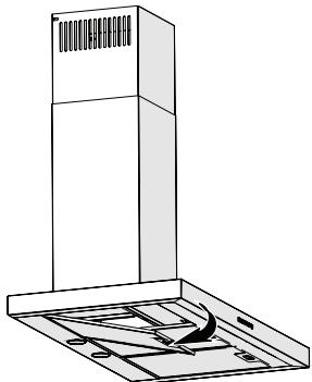
2 General Appearance
2.1 Overview
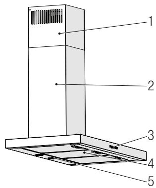
(Figure 2)
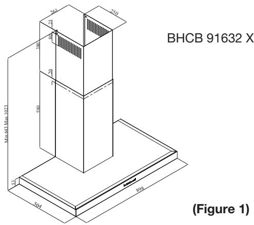
(Figure 1)
- Inner Chimney
- Outer Chimney
- Control Panel
- Aluminum Grease Filter
- Lighting
2.2 Technical Data
| Model | BHCB 91632 X |
| Supply voltage | 220-240V ~ 50 Hz |
| Lamp Power | 2 x 3 W |
| Motor Power | 210 W |
| Flow rate (m³/h) – 3. Level | 616 m³/h |
| Insulation Class of Motor | Class F |
| Insulation Class | Class I |
3 Operation of the Appliance
3.1 Controlling the Appliance
1
A
2
B
3
C

D
| KEY | FUNCTION |
| (A) : 1. Stage Button | Operates the appliance on 1st speed. When you press this button again to turn off the appliance, the screen speed stage turns off. |
| (B) : 2. Stage Button | Operates the appliance on 2nd speed. When you press this button again to turn off the appliance, the screen speed stage turns off. |
| (C) : 3rd Stage Button | Operates the appliance on 3rd speed. When you press this button again to turn off the appliance, the screen speed stage turns off. |
| (D) : Light On / Off | You may illuminate the cooking area by pressing this button. Re-press the button to turn off the lamp. |
3.2 Energy Efficient Usage
- When using your appliance, adjust the speed settings according to vapour and odour intensity, in order to save energy.
- Use low speeds (1-2) under normal conditions, and high speed (3) for intense odour and vapour.
- *The lamps on the hood are placed for illuminating the cooking area.
Using them for environmental lighting shall cause unnecessary energy expenditure and insufficient lighting.
3.3 Operating the Hood
- Your appliance contains a motor that has various speeds.
- For better performance, we recommend using low speeds under normal conditions and high speeds in cases of strong odours and intense vapour.
- You can start your appliance by pressing on the desired speed setting button. (A, B, C)
- You may illuminate the cooking area by pressing the lamp (D).
3 Operation of the Appliance
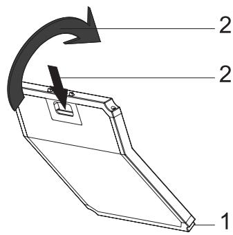
3.4 Replacement of Lamp
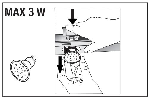
(Figure 3)
Make the electrical connections of the appliance. Your appliance uses 3W spot LED lamp. For replacing the lamps, push downwards on the holder from its behind, turn it counter-clockwise, and take it out downwards. Apply the above operation in reverse to install new lamps (Figure 3).
| Bulb | ||
| Bulb Power (W) | 3 | |
| Holder / Socket | GZ 10 | |
| Bulb Voltage (V) | 220 - 240 | |
| Size (mm) | 53 x 50 | |
| ILCOS Code | DR/F3-220-240-GZ10-50-53 | |
3.5 Operation with Chimney Connection
Vapour is extracted through the flue duct, which isfasconnection head on the hood.
- The diameter of the flue duct must be the same as the connection ring. In horizontal settings, the pipe has to have a slight upward slope (around 10^ ) so that the air can exit the room easily.
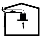
3.6 Operation without Chimney Connection
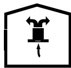
Air is filtered through the carbon filter and recirculated in the room. Carbon filter is used when it is impossible to use a flue in the house.
- In flueless use, remove the flaps inside the flue adapter.
- Remove the aluminum grease filter. To install the carbon filter, fit the filter to the tabs by centring it on the plastic piece on both sides of the fan body. Tighten it by turning right or left.
- Replace aluminum grease filter.
4 Cleaning and Maintenance

Before cleaning and maintenance, unplug the product or turn off the switch.
4.1 Cleaning of Aluminum Grease Filter
Aluminum grease filter is used to retain the oil particles in the air. Aluminum grease filter may change colour after repeated cleaning. This is normal, and you do not have to replace your filters.
(Figure 4)
- Push the aluminum grease filter lock forward.
- Then pull it slightly down and pull it out (Figure 4). Otherwise, you may bend the filter. Wash and rinse aluminum grease filter with liquid detergent and replace aluminum grease filter to their seats by carrying out the steps specified above in reverse order. These aluminum grease filter are used to retain the oil particles in the air.

You may also wash the aluminum grease filter in the washing machine.

CAUTION
In case of normal use, clean your aluminum grease filter once in a month.
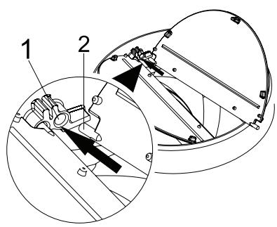
4.2 Replacement of Carbon Filters
(Fig. 5)
The appliance you have purchased is appropriate for use with carbon filters.
- Remove the aluminum grease filter (Figure 4).
- Place the lower part of the carbon filter to the motor cabinet (Figure 5).
- Press on the tab of the carbon filter and push it forward, and ensure that the tabs of carbon filter are engaged and locked. (Figure 5).
- Attach the aluminum grease filter.

CAUTION
Carbon filter shall never be washed.

CAUTION
Replace carbon filters once every 3 months.

CAUTION
You can obtain the carbon filter from the authorized services.
For the installation of the hood, please contact the nearest Authorized Service.
It is the customer's responsibility to prepare the location and electrical installation of the hood.
5.1 Position of the Appliance
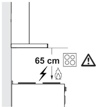
(Figure 6)
- Distance between the cooker and the cooker hood must be considered prior to assembly. This distance should be 65cm (Figure 6).
- Distance must be measured from the surface of grate for gas cookers,
- from surface of glass for electric cookers.
5.2 Installation Accessories
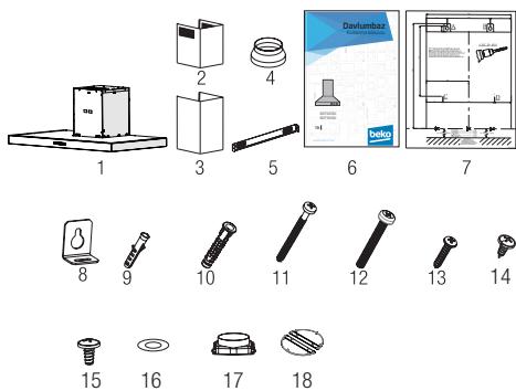
- Product
- Inner Chimney
- Outer Chimney
- 150 / 120mm Plastic Flue Adapter
- Chimney Connection Plate
- User Manual
- Assembly Pattern
- 2x Hanging Plates
- 2x 06mm Plastic Dowel
- 4x 010mm Plastic Dowel
- 4x 5.5x60 Wall Mount Screw
- 2x M5x35 Hanging Plate Connection Screw
- 2x 3.9x22 Chimney Connection Plate Screw
- 2x 3.5x9.5 Chimney Connection Plate Screw
- 2x 3,5X9,5 Blind Screw
- 2x M4 Washer
- Plastic Adapter (Square to Round)
- Non-Return Valve
The information required to make the location suitable for the installation of the hood is given below.
5 Installation Of Appliance
5.3 Wall Mounting
- Wall must be flat, straight and have the sufficient bearing capacity.
- Depth of drilling holes must comply with the length of bolts.
- The bolts and dowels provided are suitable for brick walls. For other construction material (e.g. drywall, plate, porous concrete), suitable fixing dowels and nuts shall be used.
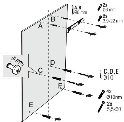

(Figure 7)
CAUTION
Before drilling, ensure that there are no power, gas or water pipes in the close proximity of the drilling locations.
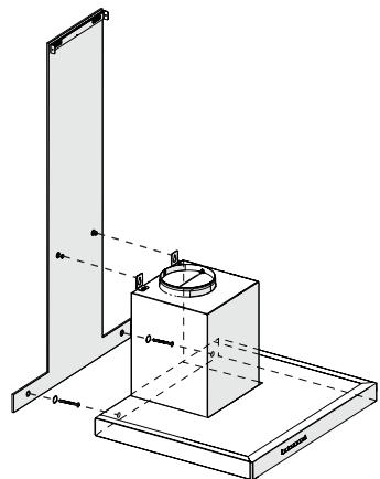
Draw a mid location line from the ceiling perpendicular to the lower edge of the hood ()
Fix the assembly scheme on the wall. For points A and B, take the maximum dimensions of the hood as reference, and drill points A and B you have marked with a 06mm drill bit, and tap 06mm plastic wall plugs. Install
the chimney connection plate to the wall with 2 pieces of 3.9 × 22 screws (Figure 8).
To install the hood body, drill points C,D,E,F specified in the installation template with a 010mm drill bit and tap 010mm plastic dowels to these points (Figure 8).
Install 2 pieces of 5.5 × 60 mounting screws to points C and D with a clearance of 5 ~mm between the screw head and the wall (Figure 8).
(Figure 8)
Install two pieces of hanging plates to the body of the hood with M5x35 mounting screws (Figure 8).
(Figure 9)
5 Installation Of Appliance
Hold the cooker hood by its body and place it on the mounting screws on the wall and tighten the screws (Figure 9).
Install M4 washers to the 5.5x60 suspension screws. Secure the cooker hood with 5.5x60 screws to the wall through the mounting hole on the interior of the appliance (Figure 9).
5.4 Connecting to Chimney
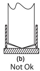
If you are going to use the 120/150 mm plastic Chimney adapter, connect one end of the pipe to this adapter, if you are not going to use it, to the direct output on the product. Connect the other end of the pipe to your Chimney. Check that these two connections are tight enough so they will not come out when the appliance runs on full power. Check if the flaps inside the Chimney operate when they are tightened
with clamps. Connect the Chimney connection duct outside the adapter (Figure 11/a). If the connection duct is fitted inside the adapter, suction of air shall not occur as the Chimney flap that prevents the return of air will remain closed (Figure 11 / b). The length of the pipe connection as well as the number of elbows must be as minimum as possible.
A:Chimney exit pipe
B:Non return flaps
C: Plastic flue
The valves are closed then the appliance is not operating and prevent possible outside odour and dust from entering inside.
(Figure 10)
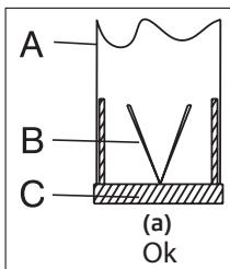
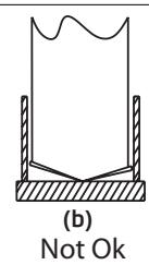
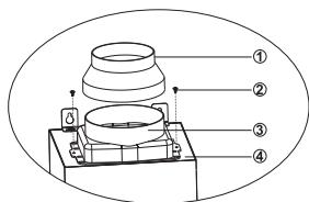
Figure 11)
(Figure 12)
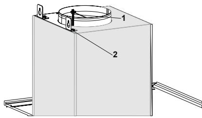
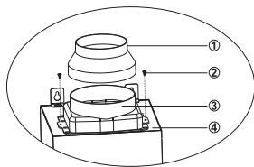
5.5 Installation of the Hood to the Chimney
Make the electrical connection of your hood before starting the installation of the Chimney. Slip the Chimney plates around the body. Install the Chimney plate to the Chimney fastening plate that is secured to the wall from its upper outer edges (Figure 13).
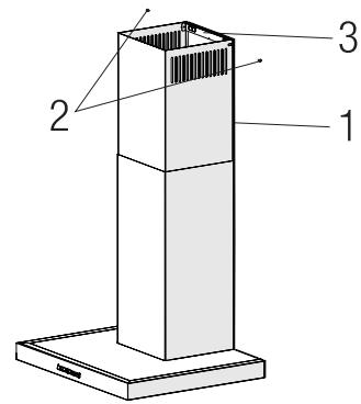
Figure 13
- Inner Chimney
- 3.5x9.5 Screw
- Chimney Connection Plate
5 Installation Of Appliance
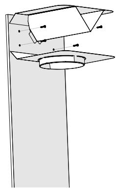
5.6 Installation of Air Baffle
While using with the carbon filter, air baffle is provided with your appliance with the aim of re-releasing the air which is cleaned with carbon filter from the perforated located on the Chimney. Assemble the air baffle as below.
(Fig. 14)
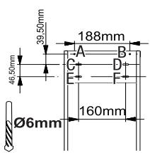
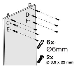
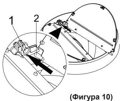
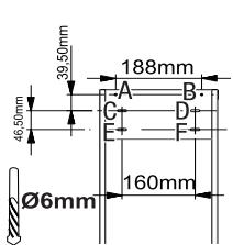
There is a tab in the middle of the Chimney connection plate. Place the middle point of this tab on the line that is drawn perpendicular to the wall. Align horizontally and mark the holes where the connection plate will be mounted via a pen (Figure 14 / A, B).
Drill the marked points with 6 mm drill and insert two 6 mm plastic dowels in the drilled holes (Figure 14 / A, B).
Fix the Chimney connection plate to the wall with 3.9 × 22 screws (Figure 14/ A, B).
For air baffle assembly, install point C, D, E, F with 6mm drill and 6mm plastic dowels (Figure 14).
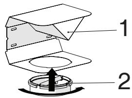
(Fig. 15)
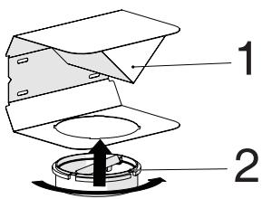
1-Air Baffle
2- Plastic Chimney
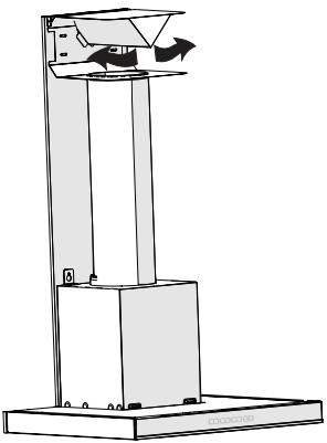
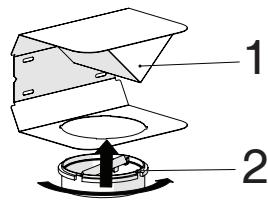
Attach the plastic Chimney adapter, which is included in the package, in the direction of the air baffle. Lock the Chimney adapter by turning it in the direction of the arrow (Figure 15).
(Figure 16)
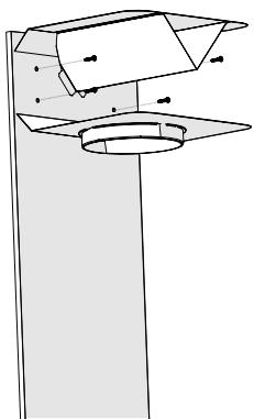
Assemble the air baffle group with 3.9 × 22 screws from point C, D, E, F that you have already prepared (Figure 14).
Assemble the hood body (Page 12 / Figure 7).
5 Installation Of Appliance
(Fig. 17)
1-Aluminium Air Outlet Pipe Make the air outlet pipe assembly (Figure 17).

Since twists and bends in the aluminium pipe will lead to reduction in the air suction power, avoid using twists and bends as much as possible.
Install the Chimney plates of the hood (Page 13 / Figure 13)
6 Troubleshooting
| Troubleshooting | Root Cause | Help |
| Appliance is not working. | Check your fuses. | Fuse may be blown, inspect and restore it. |
| Appliance is not working. | Check the electrical connection. | Mains voltage shall be between 220 and 240 V. |
| Appliance is not working. | Check the electrical connection. | Check if other appliance in your kitchen operate. |
| Illumination light does not operate. | Check the electrical connection. | Mains voltage shall be between 220 and 240 V. |
| Illumination light does not operate. | Inspect the lamp switch. | Lamp switch shall be at "on" position. |
| Illumination light does not operate. | Inspect the lamps. | The lamps of the appliance shall illuminate. |
| Air inlet of the appliance is inadequate. | Inspect the aluminium filter. | Under normal operating conditions, aluminum grease filter shall be cleaned at least once in a month. |
| Air inlet of the appliance is inadequate. | Check the air discharge chimney. | The air discharge chimney shall be at "on" position. |
| Air inlet of the appliance is inadequate. | Inspect the carbon filter. | The filters of the appliances with carbon filters shall be replaced once in every 3 months under normal conditions. |
1.4 Informations concernant I'emballage

For air baffle assembly, install point C, D, E, F with 06mm drill and 06mm plastic dowels (Figure 13).
(Fig. 14)
PRECAUCION: Las partes accesiblesSEOSEOSEOSEOSEOSEOSEOSEOSEOSEOSEOSEOSEOSEOSEOSEOSEOSEOSEOSEOSEOSEOSEOSEOSEOSEOSEOSEOSEOSEOSEOSEOSEOSEOSEOSEOSEOSEOSEOSEOSEOSEOSEOSEOSEOSEOSEOSEOSEOSEOSEOSEOSEOSEOSEOSEOSEOSEOSEOSEOSEOSEOSEOSEOSEOSEOSEOSEOSEOSEOSEOSEOSEOSEOSEOSEOSEOSEOSEOSEOSEOSEOSEOSEOSEOSEOSEOSEOSEOSEOSEOSEOSEOSEOSEOSEOSEOSEOSEOSEO SEO
HnTΦnITbP Ce n3NON3Ba, KOraTo e HeBb3MOxHO Da Ce n3NON3Ba dN-MOOTBOD B KbIaTa.
- Пи уnotpe6а 6e3 ДИМOOTBOД n3-BaIeTe KaIauNTe OT ДИМOOTBOДnIЯ aIaIaNTep.
- Изва对接е MacSENЯ ФиNTьр. 3a Да Инсталларе ВьглерODня ФиNTьр, NOCTaBeTe ФиNTьра Вьрху pa3deJInte, KaTO Г ueHTPN-paTe Bvpxy ПlaCTMaCobOTO napYe OT DBete CTpaHn Ha TЯЛOTO Ha BeHTNlAToPA, 3aTeHHeTe Ro, KaTO 3aВbPTITE HaNrCHO NIN HaNIABO.
- CmeHete anyMnHneBna MacJeH cnIbP.
KapboHOBnT pntb npHKOra He TpaBa Da ce Mne.

BHIMAHHE
CmeHnTe BbIpeOpHnTe 6nTpN BeHbX Ha BCEK 3 Mecea.

BHIMAHNE
Moxete da 3akynite BbIpeoHnA φnITbp OT OTOPI3npAHn TbproBcN.
3a MOHTaxa Ha acnnpatopa ce CBpbKeTe C ha-6n3kn OTOpN3npaH cepBn3.
OTROBOPHOCT Ha KJIneHTa e Da nOJTROTBN MeCTOnOJIOXeHNeTO N eEKeTpUYeCKaTa IHCTaJaunHa acnnpaTopa.
MoHTnpaIte 7aIb6n M4 Ha BnHToBete 3a OkaUbaHe 5.5x60.3akpeNeTe acnnpaTopa c BnHT 5.5x60 KbMCTeHaTApne3 MOHTaxHnry OTBOP OT BbTpEShHaTa CTrpaHa Ha ypeDa (ФИrpa9).
5.4 Cbþp3BaHe KbMДиMOOTBODa
Ako n3nON3BaTe nlaCTMaOBnna aanTep 3a DnMOOTBOD 120/150 MM, Cbpxkete eHNnKpaHn Tpb6bata KbM TO3n aanTep, aKO Hma Da rO n3nON3BaTe, KbM dIpeKTnna n3XoJ Ha npOdykTa. Cbpxkete dpytna KpaHn Ta Tpb6bata KbM Ba7n daNMOOTBOD. PpOBepe DaJIn Te3n DBe Bp3Kn Ca DOCTaTbUHO CTeHATn, 3a Da He N3Jra3aT, KOrato ypeDbT paBOTn C PbJHa MOsHocT. PpOBepe TaJIn KJaanITE B DnMOOTBODa pa60TAY, KOrato Ca 3aTeHATn
cBc cKo6n. CbBypKeTe dIMMOOTBOHnKaHaJ n3BbH aAnTepa (Φnrypa 11 / a). Ako CbByp3BaAunr T KaHaJ e MOHTnpaH BbTpE B aAnTepa, He Tp8Ba Da ce n3CMyKBa Bb3DyX, TbN KaTO dIMMOOTBoDbT, KOITOnpeDoTbPaTaBA BpbUshaHTo Ha Bb3Dyxa, Ie OCTaHe 3aTBOpEn (Φnrypa 11 / b). DblnxHaTa Ha TpbOHaTa Bpb3Ka, KaTO n Oporr Ha TpbOte TprBa Da 6bDe Bb3MOxHO Ha-MaJIbK.
A:ДИМоOTВОДнaи3XODHa Tрьба
B:Bb3BpaTHN Klaan
C:Пл actmacOBДИМOOTBOI
Bentnnte ca 3aTbOpEH, toraba ypeIbT He pa6OTn I ppeIoTbPaTBA HABIN3aHETO Ha BbHsHa MIn3Ma n npax.

(Фигура 11)
5.5 MoNTaX Ha AcnnpaTopa KbM DmOOTBODa
HanpaBete eJektpnueckata Bpb3ka Ha acnPnpatopa, npedn da 3aNochTe nHCTaJInpaHTo Ha dIMoOTbOda. Plb3HeTe dIMoOTbODHnte pIOOn OkOTo TAnOTO.
5.6 MoNTax Ha Bb3dUsha PperpaJa (BHCB 63640 BH)
IOKaTO n3NoJ3BaTe C BbIpeOpHnA ΦnITbp, C BaShnYpeD ce OcnrypRyBa Bb3dUsha NpePpaDa C ueJ daOCBO6OInde Bb3dyxa, KOHTo Ce NOcHCTBa C BbIpeOJeH ΦnITbp OTNepOpnpaHn, pa3noJoxeH Na DmMOOTbOda. CrNo6Te Bb3dUshaTaNpePpaDa KaKTo e POKa3aHO No-DoJny.

(ФИг.13)
B cpeaTa Ha nloyata 3a DnmoOTbOJa mMa pa3dJeNITe. NocTabeTe CpeHaTAtoUka Ha To3n pa3deN Bbpx JInHra, KOrTo e HaueptaHa nepneHnKuJrpHo Ha CteHata. IoppaBHeTe XOpn3oHTaJIHo n MapKnpaIte OTBOPnte C xIMNKaJIka, KbDeTo ige 6bJe MOHTnpaHa CBbp3Ba-uaTa nloya (Fnrpya 13 / A, B).
Прбишte Маркпанite ToчК n 6opMaunHa 66 MM N BmBkHeTe DBe 6MMПл actmacOBnДIO6eNВпрбntte OTbOpn (ФИгура 13/A,B).
3aKpeIeTe DmOOTBOdHaTa NIOUa KbM CTeHaTa C BnHTObe 3.9x22 (ФИура 13/A,B).
3a MOHTaKa Ha Bb3dUyShHaTa npe- rpa, npo6nTe TocKn C,D,E,F Cbc CBpeJIO 06 MM n NoctaBeTe PnactMacOBnTe DIO6eN NMM (FInrpya 13).
(ФИг.14)
1-Bb3duyHa nperpapa
2-Пл actmacobДИМOOTBOI
PnKpeTe nJaCTMaCObN aJaTep 3aДIMOOTBODa, KOITo e BkJIIOueH B NaKeTa, NO NOCOKa Ha Bb3-DyUHata npErpaJa. 3akpenete DImOOTBOHnA aJaTep, KaTO rO 3aBbPTNTe B NOCOKaTa Ha CTpeIKNaTa (Фигура 14).
(Фиура 15)
Crnoobete rpynata Ha Bb3dyuHaTa nperpada c 3,9 x 22 BNHTa OT TOUKN C,D,E,F,KoNTO Beue cTe NOIroTBnJn (ΦnIpya 13).
Crtnobete TaIOnTo Ha acnnpaTopa (Ctpanuca 12 / Phnypa 7).