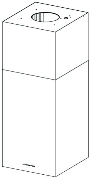
CUBIA ISOLA PLUS - Range hood FABER - Free user manual and instructions
Find the device manual for free CUBIA ISOLA PLUS FABER in PDF.
| Product type | Island extractor hood |
| Brand | FABER |
| Model | CUBIA ISOLA PLUS |
| Mode of use | Extracting (ducted) or recirculating (charcoal filter) |
| Housing material | Stainless steel and glass (depending on version) |
| Number of speeds | 3 speeds + intensive speed (10 min) |
| 24H function | Yes - extraction for 10 min every hour at speed 1 |
| Delay function | Yes - automatic delayed shut-off after 30 minutes |
| Lighting | 2 halogen lamps 20 W each |
| Anti-grease metal filters | Dishwasher safe |
| Activated charcoal filter | Not washable, replace every 4 months (FC indicator) |
| Electrical supply | 220-240 V ~ 50/60 Hz |
| Electrical class | Class I (earthing mandatory) |
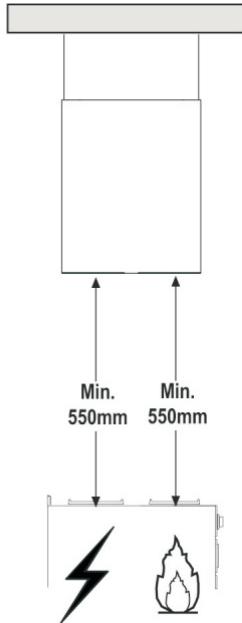
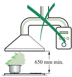
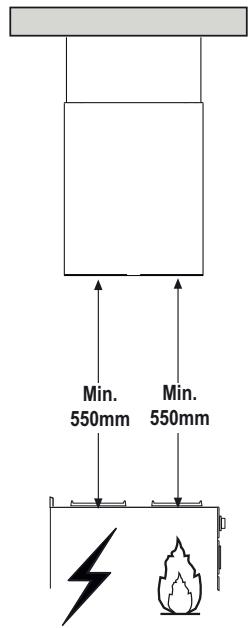
| Minimum safety distance | 650 mm between the cooking hob and the hood |
| Duct diameter | 120 mm or 150 mm |
| Remote control | Optional (not supplied, LR03-AAA batteries) |
| Installation type | Ceiling mounting (island) on telescopic frame |
| External maintenance | Damp cloth and neutral detergent |
Frequently Asked Questions - CUBIA ISOLA PLUS FABER
User questions about CUBIA ISOLA PLUS FABER
0 question about this device. Answer the ones you know or ask your own.
Ask a new question about this device
Download the instructions for your Range hood in PDF format for free! Find your manual CUBIA ISOLA PLUS - FABER and take your electronic device back in hand. On this page are published all the documents necessary for the use of your device. CUBIA ISOLA PLUS by FABER.
USER MANUAL CUBIA ISOLA PLUS FABER
MOHTaX Ha KOMHa MoHTaX Ha Kopnyca Ha anCupaTopa
-Пoctabete rohpHЯ KOMHи rO ФнсpaHTe B roPHaTMy aCT KbM paMKaTa, n3NoJ3yBaHKn DoCTaBeHnTe 4 BnHTa 12c (2,9x9,5) ot OKOMJIeKToBkata.
HnIITpnpaasaBepcnia
- YBepete ce, Ye n3xoJnIaT OTBOp Ha yIbJnKeHneTo Ha CBpb3kata Ha Bb3dUxOBoJa 15e NOCTaBeHa npaBnJIHO, Taka Ye peWetKaTa Ha n3xoJnIaN OTBOp CbBnJa c Ta3n Ha KOMInHa.
-Ako peWetKnte Ha IBeTe Yactn He CbBnaIaT, Iue 6bIe Heo6xOIMo Da OTCpaHInTe KOMHa N da peryInpaTe NOJIOXeHNTo Ha CBp3kata 15 n Hakpa Da cTNO6nte OTHOBO YactnTe, CJIeDBAIKn PpeDNsHInTe IHCTpyKcIM.
IopmHa Ha qnItbpa aKTHBcH BbTneH
- N3terJIeTe KOMΦoPT nAHeIInTe, 3a Da I n OTBOpNTe.
-Ⅰ3BaTeMeTaJIHnTeФиЛТрИЗаMa3HNHn.
-ИЗвадеTe HacnteHЯФиNTbР aKtINBeH BblIeH KaTO OCBO6OДTeФИКСИраUNTe пALI.
-Пoctabete HOBnIФИТьр И Го 3aTeHHeTe B HerOBaTa ПраВинHa ПОЗИЦИ.
-ПocTaBeteMeTaNHITeФиNTpN3aMa3HnHbTexHITeTHe3da. - 3aTbOpTe KOMΦoPΓ-ПаHEnIte.
OcbetJIeHne
CMRAHA HA KPYUKITE 20 W XanoreHna lamma
-MaxheTe 2-Te BnHTeTaT,3aIbPkaunΦacyHraTa Ha KpyuKaTa n I N3TerIeTe OT acnnpaTopa
- ɪnɜːdæteɪnʌmɪrataʊtɒfəcɪyhrata.
-CmeHete r c HOBa CbC cbUHTe XapaKTePncTkn, KaTO BHNMaBaTe Da nocTaBnTE Do6pe DBeTe KpaYeBA CeINoTo IM.
-MontpaTe OTHOBO facyHraTa C OTBNTe Ipei N DBe BnHTyeta.
CnmbonbT Bbypny npodykta nIIN Bbypxy dokymeHa npndpyjkaa npodykTa noka3Ba, ye To3n ypei He Tpr6Ba da ce TpeTnpa KaTO domaknHcN OTnAdbu. BmecTo TOBA ToT pr6Ba da ce npdahe Ha noDxOJaSna c6opeH nyKt 3a peunKnpaHe Ha eJekTpueckn eJekTPOHHu ypei. YnUoXoKaBaHeTo Tpr6Ba da CE n3BbpNn B CbOTBeTCTBne C MeCTHnTe 3aKOHN 3a Ona3BaHe Ha OKoHaTa Cpea N yHniOxoKaBaHe Ha OTnAdbu.
CUBIA ISOLA EG10
CUBIA ISOLA GLOSS EG10
Pošovani klijenti
Mi Vam se zahvaljujemo sto ste izabrali aspirator Faber, jeder prestižan brend, sinonim za kvalitet i sigurnost. adamo se da ce on zadovoljiti sve vaš potrebe. Ukoliko pažljivo pratite preparuke koje su date u uputstvu Vaš ce aspirator ostati efikasan. Nemojtse se dvoumiti da nas potražite. Mi smo tu odmah do vas kako bi Vam pomogli, I kako bismo Vam dali korisne informacije za sve proizvode brenda Nardi.
PREPORUKE I SAVETI
Instrukcije za upotrebu se odnose na nekoliko modela ovog uredaja. Prema tome, mozete naici na opise pojedinih karakteristika koje se ne odnose na Vaš specičan uredaj.
MONTIRANJE
Proizvoda se nece smatrati odgovornim za bilo kakvu stetu nestalu kao posledica nepravilnog ili netačnog montiranja uredaja.
Minimalno bezbedno rastrojanje izmedu vrha sporeta i aspiratora treba da je 650 mm (kod nekih modela se moze montirati na manjoj visini, molimo Vas da obrata paznju na odeljke o radnim dimenzijama i montiranju.)
Proverite da li napon u Vasem prostoru odgovara naponu naznačenom na tablici sa podacima, a koji je se nalazi unutar aspiratoria.
Za I klasu kućnih aparata, proverite da li kućno snabdevanje el. energijom garantuje adekvatno uzemljenje.
- Povežite aspirator sa ispusnim dimnjakom pomócu cevi minimnog prečnika 120 mm. Dužina cevi mora biti što je moguce krača.
Nemojte povezivati aspirator na odvodne cevi koje su nosioci dimnih isparena (bojleri, kamini itd.)
Ako se aspirator koristi u kombinaciji sa neelektrichim uredajima (na primer uredajima na plin) u prostoriji mora biti obezbeden odredeni stepen provetrenosti kako bi se sprecio vracanje izduvnog gasa. Kuhinja mora posedovati otvor koji direktno komunicira sa otvorenim vazduhom kako bi se zarantovao ulaz Čistog vazduha
UPOTREBA
Aspirator je ekskluzivno kreiran za kućnu upotrebu, kako bi se eliminisali kuhinjski mirisi.
Nikada nemojte koristiti aspirator u druge svrhe osim u one za koje je konstruisan.
- Nikada ne ostavljaje otvoren plamen ispod aspiratora dok aspirator radi.
- Podesite intenzitet plamena takado idessamo ispod sua i proverite da ne kruzi sa strane.
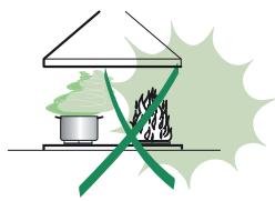
Rad friteze tokom upotrebe mora biti strogo nadgledan: pregrejano ulje moze dovesti do eksplozije.
Nemojte flambirati ispod aspiratora (rizik od vatre).
- Ovaj uredaj nods namenjen osobama (ukljucujuci i decu) sa smanjenom psihickom, senzornom ili mentalnom spsojobnoscu ili nedostatkom iskustva u poznavanju uredaja, osim ako im nisu date instrukcije kako da koriste uredaj ili ako ih nadgleda lice odgovorno za njihovu bezbednost.
Decamoraju biti nadgledana kako se ne biigrala sa uredajem.
- OPREZ: Dostupni delovi mogu postati vruci ukoliko se koriste sa kuhinjskim uredajima.
ODRZAVANJE:
Isključite aparat ili izvucite gajtan iz štekera pre obavljanja bilo kakvog posla u vezi sa odžavanjem urežaja.
Ocistite i/ ili zamenite Filtere nakon nazanačenog vremena (Opasnost od požara).
Ocistite aspirator vlaznom krpom i neutralnim tecnim deterdzentom.
KARAKTERISTIKE
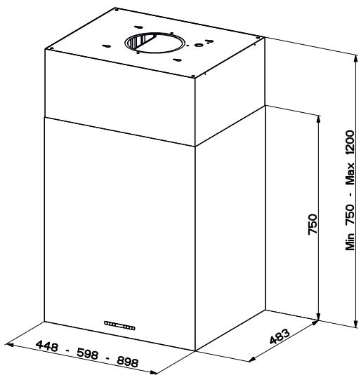
DIMENZije
KOMPONENTE
| Ref. | Q.ty. | Komponente proizvoda |
| 1 | 1 | Telo aspiratora, kompletno sa: Kontrolama, Svetlima, Ventilatorom, Filterima |
| 2 | 1 | Gornji dimnjak |
| 7.1 | 1 | Teleskopski okvir zajedno sa ekstraktorom, sastavljenim od: |
| 7.1a. | 1 | Gornji okvir |
| 7.1b | 1 | Donji okvir |
| 9. | 1 | Reduktor bandaže ø 150-120 mm |
| 13 | 1 | Zaptivka (zaptivač) |
| 14 | 1 | Deo za proširenje vizdušnog ispusta aspiratora |
| 15 | 1 | Konektor za izlaz vizduha |
| 25 | 2 | Cevne spojnice (nisu ukljčene u paket) |
| 26 | 1 | Pričivrssi deo gornjeg dimnjaka |
| 29 | 1 | Prikljucak za cev vizdušnog ispusta |
| 11 | 4 | Zidni tiplovi ø 10 |
| 12c | 4 | Śrafovi 2,9 x 9,5 |
| 12f | 2 | Śrafovi M6 x 15 |
| 12g | 4 | Śrafovi M6 x 80 |
| 12h | 4 | Śrafovi 5,2 x 70 |
| 12q | 4 | Śrafovi 3,5 x 9,5 |
| 21 | 1 | Šablon za bušenje |
| 22 | 8 | Podloške unutrašnjeg prečnika 6.4 mm |
| 23 | 4 | M6 navrtke |
| 24 | 2 | Pričvrsni dugmići za deo konekcije vazdušnog ispusta |
Kol. Dokumentacija
1 Upstvo za upotrebu
MONTAZA
Bušenje plafona/ nosača i pričvršćivanje fiksirajućeg rama
BUŠENJE PLAFAONA/ NOSAÇA
- Koristite vertikalnu liniju kako biste obeležili centar ploče na plafonu/ pomocnom nosaču.
- Postavite šablon za buşenje 21 na plafon/ potporni nosač, vodeci računa da šablon bude u ispravnom položaju, centrirajući osovinu šablona sa onim na ploči.
- Obelezite centre rupa na šablonu.
- Izbušite rupe na naznačenim tačkama:
Za betonske tavanice, izbušite rupe takto da odgovaraju odgovarajućoj velicini zavrtnja.
- Kod plafona od šuplje opeke, debljine zida od 20mm: bušilica Ø 10 mm (odmah ubacite Tiplove 11, koji se nalaze u pakovanju.)
Kod drivenih plafonsikh greda, bušite prema drvenim šrafovima koje koristite.
Kod drivenih tavanica, bušite 7 mm.
Za kabal napajanja el. energijom, busilica 10mm
Za vazdušni izlaz (cevna verzija), bušite prema prečniku prikljúčka społjašnjeg izduvnog izlaza cevi.
- Ubacite dva šrafa odgovarajućeg tipa, ukrštajuci ih i ostavljajuci ih na 4-5 mm od plafona:
Kod betonskih tavanica, koristite odgovarajuće priključke velicine šrafa (nisu uključeni u pakovanje).
Kod šupljih plafona, koji imaju unutrašnji prostor, debljine zida od oko 20mm, koristite šrafove 12, koji su u pakovanju.
Za plafonske drivene tavanice, koristite 4 drvena šrafa (nisu uključeni u pakovanje.)
Za drvenu tavanicu, koristite 4 drvena šrafa 12g sa podlošcima 22 i navrtnjima 23, koji se nalaze u pakovanju.
MONTIRANJE OKVIRA
Ukoliko Želite da podesite visinu okvira, postupite prema sledećem:
- Odśrafite metričke šrafove koji pričvršćuju dve kolone a nalaze se sa strana okvira.
- Podesite okvir na zahtevanu visinu a potom zamenite sve šrafove koji su uklonjeni kao na slici.
- Pricvrstite Pričvrsni deo gornjeg dimnjaka 26 na visécu opremu upotrebom 2 šrafa 12 w (M3x 8).
- Podignite okvir, pričvrstite do kraja otvore okvira na rupe za šrafove.
- Pričvrstite dva šrafa i pričvrstite druga dva šrafa, koji su u pakovanju sa dimnjakom; Pre no što potpuno zašrafite šrafove, moguce je podesiti ram takto što cete ga okrenuti. Vodite računa da šrafovi ne izlaze sa svog mesta u prorezima rupa.
- Sada je moguce postaviti i pričvrstiti 4 bezbedonosna šrafa.
Postupite na sledeci način:
- Bušite plafon sa bušilicom 0 10 mm uzimajuči kao referentne rupe sa bočnih delova gornjeg pričvrsnog dela dimnjaka.
Umetnite 4 klipa (obezbedeni).
Umetnite podloške (obezbečene) na šrafove i zategnite šrafove.
Prikljucivanje na vazdušni ispust kod cevne verzije systemd
Kada montirate cevnu verziju povežite aspirator sad dimnjakom koristeci fleksibilne ili krute cevi 150 ili 120mm izbor je prepuşten instalateru.
- Da biste montirali konektor za vizdušni ispust 0 120mm, ubacite reduktor bandaje 9, na ispusni otvor dimnjaka.
Fiksirajte cevi pomocu stezaljke 25 (nije obezbebënda u paketu)
Uklonite sve filtrere sa aktivnim ugljem.
Verzija sa recirculacionim vazdušnim ispusnim otvorom
- Umetnite reduktor bandaze 9 na vazdušni ispust aspiratora. Pričvrstite adhezivnu Novastik zaptivku (zaptivač) 13 na Konektor za izlaz vazduha 15 i pričvrstite ga na gornji okvir pomoću 2 dugmíca 24.
- Pričvrstite deo za proširenje vázdušnog ispustaspiratora 14 na Konektor za izlaz vázduha 15.
Postavite prikljucak za cev vazdu-snog ispusta 29 izmeu dva ispusta.
Montiranje dimnjaka
Posicionirajte gornji dimnjak i pričvrstite gornji deo na okvir upotrebom 2 obezbedena šrafa 12c (2,9x6,5).
20 W xanorehcko CBeTIO.
- ɪЗbaɪdete ro kanaueTe ha cBetɪnɪkɑta co OɒbPtyBaɪhæ Ha HæbPtkɪte.
- I3BaDeTe ja CBeTnIkata OJ DpKzauOT.
3aMeHeTe ja oN IcT Bn,I He 3a6OpabajTe da npOBepTe daJI NDbTe INJIe Ce npaBnHNO NOCTaBeHN BO JekuSTeTO Ha dPkaOT Ha CBETIOTO.
BpaTeToIpxaOTnФKcnpajTe coDbTe HABrTKn KOI 6ea N3BaJeH.
CmboJOT obeljxah Ha ypeoT, nIIO obeljxah Ha Herobata DOKymeHTaunja, NOKaJyBa deka ToJ ypei He cMee Da ce TpeTnpa KaKo Domauhen OTnad. HameTo Toa Toj ypei Tpe6a Da ce npdae BO HajbNCKNt PnykT 3a peuKnnpaHe Na eNEKTPnKn IN eNEKTPoHcKn ypei. YnHsTuBaBeTo Tpe6a Da Ce N3BpUH BO COrnAChOCT CO JOKaJIHnTe 3aKOHn IN BO COrnAChOCT CO cTaHapDInTe 3a KINBOTHaTa CpeDiHa .
Instructions Manual
Gebruiksaanwijzing
PykoBoDcTBo nO 3KcnIyatauIN
RECOMMENDATIONS AND SUGGESTIONS
The Instructions for Use apply to several versions of this appliance. Accordingly, you may find descriptions of individual features that do not apply to your specific appliance.
INSTALLATION
- The manufacturer will not be held liable for any damages resulting from incorrect or improper installation.
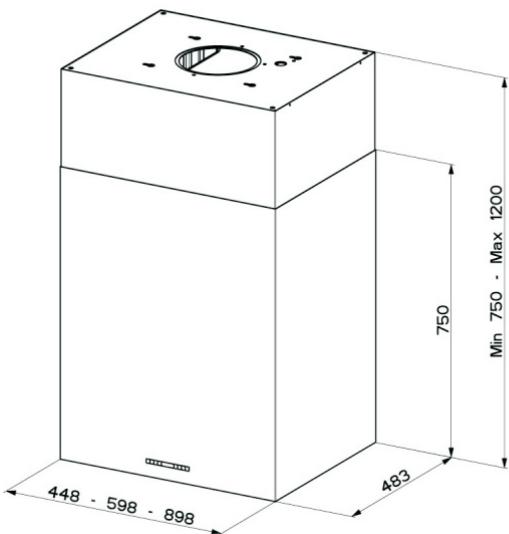
- The minimum safety distance between the cooker top and the extractor hood is 650mm (some models can be installed at a lower height, please refer to the paragraphs on working dimensions and installation).
- Check that the mains voltage corresponds to that indicated on the rating plate fixed to the inside of the hood.
- For Class I appliances, check that the domestic power supply guarantees adequate earthing.
Connect the extractor to the exhaust flue through a pipe of minimum diameter 120~mm . The route of the flue must be as short as possible.
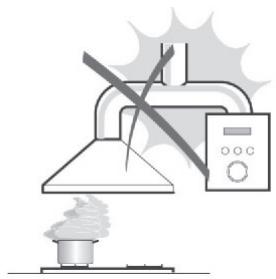
- Do not connect the extractor hood to exhaust ducts carrying combustion fumes (boilers, fireplaces, etc.).
- If the extractor is used in conjunction with non-electrical appliances (e.g. gas burning appliances), a sufficient degree of aeration must be guaranteed in the room in order to prevent the backflow of exhaust gas. The kitchen must have an opening communicating directly with the open air in order to guarantee the entry of clean air. When the cooker hood is used in conjunction with appliances supplied with energy other than electric, the negative pressure in the room must not exceed 0.04 mbar to prevent fumes being drawn back into the room by the cooker hood.
- In the event of damage to the power cable, it must be replaced by the manufacturer or by the technical service department, in order to prevent any risks.
USE
- The extractor hood has been designed exclusively for domestic use to eliminate kitchen smells.
- Never use the hood for purposes other than for which it has been designed.
- Never leave high naked flames under the hood when it is in operation.
- Adjust the flame intensity to direct it onto the bottom of the pan only, making sure that it does not engulf the sides.
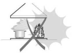
- Deep fat fryers must be continuously monitored during use: overheated oil can burst into flames.
- Do not flambé under the range hood; risk of fire
- This appliance is not intended for use by persons (including children) with reduced physical, sensory or mental capabilities, or lack of experience and knowledge, unless they have been given supervision or instruction concerning use of the appliance by a person responsible for their safety.
Children should be supervised to ensure that they do not play with the appliance. - “CAUTION: Accessible parts may become hot when used with cooking appliances.”
MAINTENANCE
- Switch off or unplug the appliance from the mains supply before carrying out any maintenance work.
- Clean and/or replace the Filters after the specified time period (Fire hazard).
- Clean the hood using a damp cloth and a neutral liquid detergent.
The symbol on the product or on its packaging indicates that this product may not be treated as household waste. Instead it shall be handed over to the applicable collection point for the recycling of electrical and electronic equipment. By ensuring this product is disposed of correctly, you will help prevent potential negative consequences for the environment and human health, which could otherwise be caused by inappropriate waste handling of this product. For more detailed information about recycling of this product, please contact your local city office, your household waste disposal service or the shop where you purchased the product.
Dimensions
Components
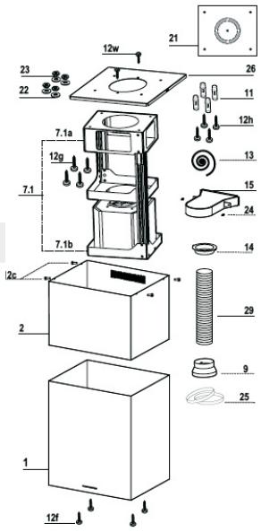
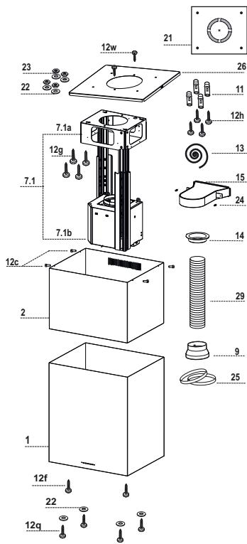
| Ref. | Q.ty | Product Components |
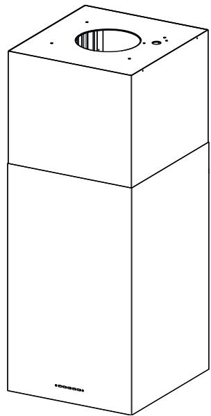
| 1 | 1 | Hood Body, complete with: Controls, Light, Blower, Filters |
| 2 | 1 | Upper Chimney |
| 7.1 | 1 | Telescopic frame complete with extractor, consisting of: |
| 7.1a | 1 | Upper frame |
| 7.1b | 1 | Lower frame |
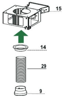
| 9 | 1 | Reducer Flangeø 150-120 mm |
| 13 | 1 | Gasket |
| 14 | 1 | Hood Body Air Outlet Extension Piece |
| 15 | 1 | Air Outlet Connection |
| 25 | Pipe clamps (not included) | |
| 26 | 1 | Fixing Part of the upper Chimney |
| 29 | 1 | Air outlet connection tube |
| Ref. | Q.ty | Installation Components |
| 11 | 4 | Wall Plugs ø 10 |
| 12c | 4 | Screws 2,9 x 9,5 |
| 12f | 2 | Screws M6 x 15 |
| 12g | 4 | Screws M6 x 80 |
| 12h | 4 | Screws 5,2 x 70 |
| 12q | 4 | Screws 3,5 x 9,5 |
| 12w | 2 | Screws M3 x 8 |
| 21 | 1 | Drilling template |
| 22 | 8 | 6.4 mm int. dia washers |
| 23 | 4 | M6 nuts |
| 24 | 2 | Fixing knobs for the air outlet connection piece |
Q.ty Documentation
1 Instruction Manual
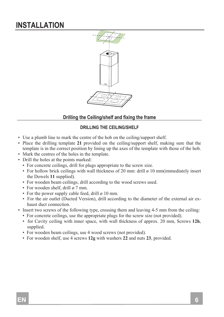
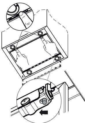
Drilling the Ceiling/shelf and fixing the frame
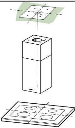
DRILLING THE CEILING/SHELF
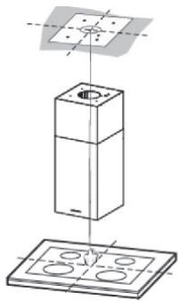
- Use a plumb line to mark the centre of the hob on the ceiling/support shelf.
- Place the drilling template 21 provided on the ceiling/support shelf, making sure that the template is in the correct position by lining up the axes of the template with those of the hob.
- Mark the centres of the holes in the template.
-
Drill the holes at the points marked:
-
For concrete ceilings, drill for plugs appropriate to the screw size.
- For hollow brick ceilings with wall thickness of 20mm : drill 10mm (immediately insert the Dowels 11 supplied).
- For wooden beam ceilings, drill according to the wood screws used.
- For wooden shelf, drill 7 mm .
- For the power supply cable feed, drill 0.10mm .
-
For the air outlet (Ducted Version), drill according to the diameter of the external air exhaust duct connection.
-
Insert two screws of the following type, crossing them and leaving 4 - 5mm from the ceiling:
-
For concrete ceilings, use the appropriate plugs for the screw size (not provided).
- for Cavity ceiling with inner space, with wall thickness of approx. 20mm , Screws 12h, supplied.
- For wooden beam ceilings, use 4 wood screws (not provided).
- For wooden shelf, use 4 screws 12g with washers 22 and nuts 23, provided.
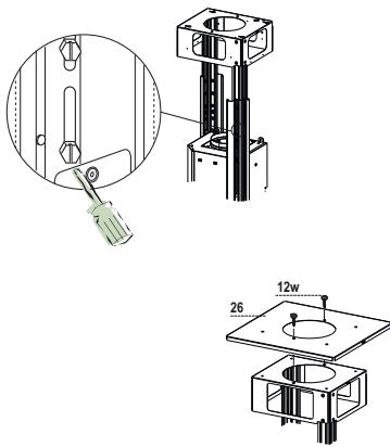
FIXING THE FRAME
If you wish to adjust the height of the frame, proceed as follows:
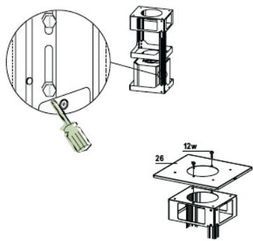
- Unfasten the metric screws joining the two columns, located at the sides of the frame.
- Adjust the frame to the required, then replace all the screws removed as above.
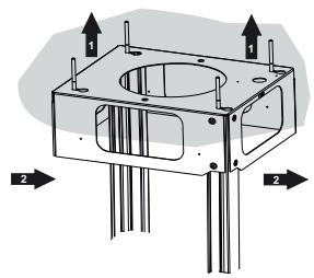
Fix the Fixing Part of the Upper Chimney 26 to the hanging kit using the 2 screws 12w (M3 x 8). - Lift up the frame, fit the frame slots onto the screws up to the slot end positions.
- Tighten the two screws and fasten the other two screws provided; before locking the screws completely, it is possible to adjust the frame by turning it, making sure that the screws do not come out of their housing in the adjustment slot.
-
It is now possible to place and tighten the 4 safety screws, Proceed as follows:
-
drill the ceiling with a 10mm bit taking as reference the holes of the side parts of the upper chimney fixing part.
- insert the 4 dowels (provided).
-
insert the washers (provided) to the screws and tighten the screws
-
The Frame must be securely fastened so as to support both the weight of the Hood and the stress caused by occasional axial pressure against the fitted Appliance. After fixing, make sure that the base is stable even when the Frame is subjected to lateral stress.
- If the Ceiling is not strong enough in the area where the hood is to be fixed, the Installer must strengthen the area using suitable plates and counterplates anchored to resistant structures.
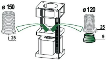
Ducted version air exhaust system Connection
When installing the ducted version, connect the hood to the chimney using either a flexible or rigid pipe 150 or 120~mm the choice of which is left to the installer.
- To install a 0.120 ~mm air exhaust connection, insert the reducer flange 9 on the hood body outlet.
Fix the pipe using the pipe clamps 25 (not provided). - Remove any activated charcoal filters.
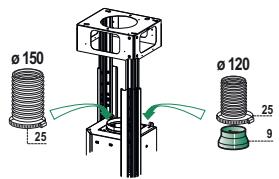
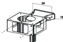
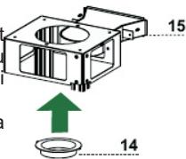
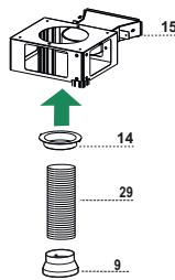
RECIRCULATION VERSION AIR OUTLET
- Insert the reducer flange 9 on the air outlet of the extractor.
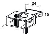
- Attach the adhesive Novastik gasket 13 to the air outlet connection 15 and fix this to the upper frame using the 2 knobs 24.
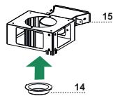
Fix the air outlet connection extension piece 14 to the air outlet connection 15. - Place the air outlet connection tube 29 between the two air outlets.
Flue assembly - Mounting the hood body
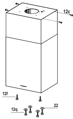
- Insert the upper duct and fix it on the top of the upper duct connection using the 12c screws (2.9 x 9.5) supplied with the appliance.
Recirculation version
- It is necessary to make sure that the air outlet connection 15 is placed correctly so that the air outlet grid in it corresponds to that of the chimney.
- If the grids of the two parts are not corresponding to each other, it will be necessary to remove the chimney and to adjust the position of the air outlet connection 15, and at last to assemble the parts again by following the earlier indications.
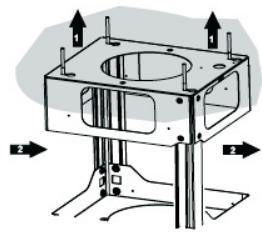
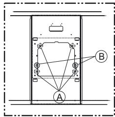
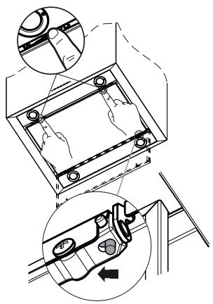
Before fixing the hood body to the frame:
- Screw the 2 screws 12f half way into the holes provided in the sides of the bottom of the frame.
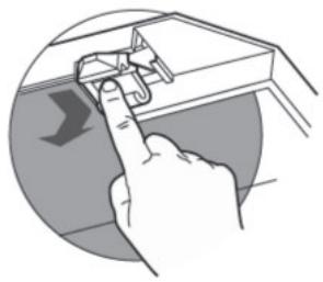
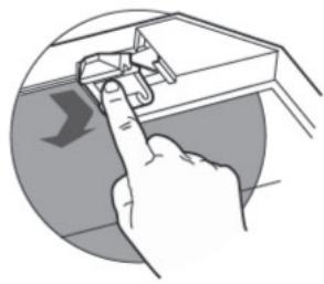
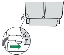
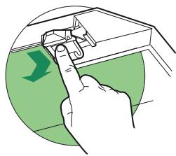
- Open the suction panel by turning the specific knob.
- Disconnect the panel from the hood canopy by sliding the fixing pin lever.
- Remove the grease filters from the hood body.
- Remove any activated charcoal filters.
- Lift the hood canopy and engage the screws 12f in the slots (A) as far as they will go.
- Working from below, fix the hood canopy to the frame (B), using the 4 screws 12q and 4 washers 22 provided, then tighten all the screws securely.
ELECTRICAL CONNECTION
- Connect the Hood to the mains power supply, inserting a two-pole cut-out switch with contact aperture of at least 3mm along the line.
- Pull the Comfort Panel to open it, ensure that the supply cable connector is properly inserted into the Suction device socket
- Join the connectors.
- Install the odour filter and the charcoal filter in case the hood is to be used in recycling version.
- Install the grease filter again, and successively the suction panel.

A

B

C

D

E

F

G

H
Control panel
| Button | Function | Display |
| A | Turns the suction motor on and off at speed one. | Displays the set speed |
| B | Decreases the working speed. | Displays the set speed |
| C | Increases the working speed. | Displays the set speed |
| D | Activate intensive speed from any other speed, including motor off. This speed is set to operate for 10 minutes, after which the system returns to the speed that was set before. Suitable to deal with maximum levels of cooking fumes. | Displays HI and the time remaining once very second. |
| Press and hold the button for approximately 5 seconds, with all the loads turned off (Motor and Lights), to turn the Activated Charcoal Filter alarm On and Off. | FC+Punto (2 flashes)-Alarm On. FC+Punto (1 flash)-Alarm Off. | |
| E | 24H function Turns the suction motor on at speed one and effects one 10 minute extraction every hour. | Displays 24 and the spot at the bottom right flashes once every second, while the motor is running. It is disabled by pressing the button. |
| When the filters alarm is triggered, the alarm can be reset by pressing and holding this button for approximately 3 seconds. These indications are only visible when the motor is turned off. | FF flashes three times. When the procedure terminates, the indication shown previously turns off. FG indicates the need to wash the metal grease filters. The alarm is triggered after the Hood has been in operation for 100 working hours. FC indicates the need to change the activated charcoal filters, and also to wash the metal grease filters. The alarm is triggered after the Hood has been in operation for 200 working hours. | |
| F | Delay function Activate automatic switch-off with a 30' delay. Suitable to complete elimination of residual odours. Can be activated from any position, and is disabled by pressing the button or turning the motor off. | Displays the operating speed and the spot at the bottom right flashes once a second. |
| Press and hold the button for approximately 5 seconds, with all the loads turned off (Motor and Lights), to turn the Remote Control On and Off. | IR+Punto (2 flashes)-Alarm On. IR+Punto (1 flash)-Alarm Off. | |
| G | Turns the lighting system on and off at maximum intensity. | |
| H | Turns the Courtesy Lighting on and off. |
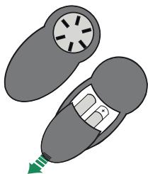
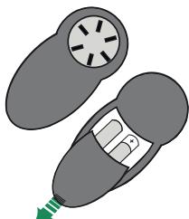
REMOTE CONTROL (OPTIONAL)
The appliance can be controlled using a remote control powered by a 1.5V carbon-zinc alkaline batteries of the standard LR03-AAA type (not included).
- Do not place the remote control near to heat sources.
- Used batteries must be disposed of in the proper manner.
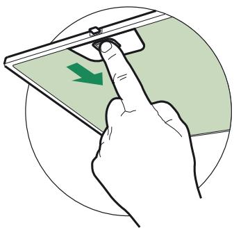
Cleaning the Comfort Panels
Pull the Comfort Panel to open it.
- Disconnect the panel from the hood canopy by sliding the fixing pin lever.
- The comfort panel must never be washed in a dishwasher.
- Clean the outside by using a damp cloth and neutral liquid detergent.
- Clean the inside as well by using a damp cloth and neutral detergent; do not use wet cloths or sponges, or jets of water; do not use abrasive substances.
- When the above operation has been completed, hook the panel back to the hood canopy and close it by turning the knob in the opposite direction.
Metal grease filters
They can be washed in the dishwasher, and need to be cleaned whenever the FG sign appears on the display or at least once every 2 months use, or more frequently if use is particularly intensive.
Resetting the alarm signal
- Turn the Lights and the Suction motor off, then disable the 24h function, if enabled.
- Press button E (see the paragraph on Use).
Cleaning the Filters
- Open the Comfort panels by pulling on the recess.
- Remove the Filters one at a time, pushing them towards the back of the unit and at the same time pulling downward.
- Wash the Filters without bending them, and leave them to dry completely before replacing. (If the surface of the filter changes colour as time goes by, this will have absolutely no effect on the efficiency of the filter itself.)
- Replace, taking care to ensure that the handle faces forwards.
- Close the Comfort panels.
Activated Charcoal Filter (Recirculation Version)
It cannot be washed or regenerated, and must be changed when the FC symbol on the display appears, or at least once every 4 months. The Alarm signal, if it has been activated, only appears when the Suction motor is turned on.
Activating the alarm signal
- In Recirculation Version Hoods, the Filter Saturation Alarm must be activated on installation or at a later date.
- Turn the Lights and the Suction Motor off.
-
Press D and hold for approximately 5 Seconds:
-
The message FC+Puntino flashes twice, A.C. Filter saturation alarm ACTIVATED
- The message FC+Puntino flashes once, A.C. Filter saturation alarm DEACTIVATED
CHANGING THE ACTIVATED CHARCOAL FILTER
Resetting the alarm signal
- Turn the Lights and the Suction motor off, then disable the 24h function, if enabled.
- Press button E (see the paragraph on Use).
Changing the Filter
- Open the Comfort panels by pulling on the recess.
- Remove the Metal grease filters.
- Remove the saturated charcoal filter by releasing the fixing hooks.
- Fit the new filter and fasten it in its correct position.
- Replace the Metal grease filters.
- Close the Comfort panels.
Lighting
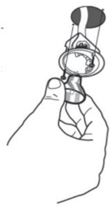
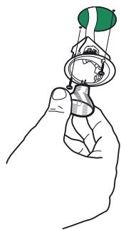
LIGHT REPLACEMENT
20 W halogen light.
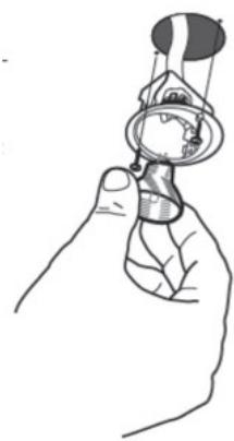
- Remove the 2 screws fixing the Lighting support, and pull it out of from the Hood.
- Extract the lamp from the Support.
- Replace with another of the same type, making sure that the two pins are properly inserted in the lamp holder socket holes.
- Refit the Support, fixing it in place with the two screws removed as above.
HactoJuee pyKOBdCTBO NO 3KcTJyataUm COCTABNEHO Ipa3hBx MoDEJI npIbOpa.Bo3MOKHO, BBy BCTpeTIte B HEM ONICAHME OTJeBbX KOMTIIEKTHyOuIX, HE OTHOCIAUXC K MOJIIM Baue- ro npIbOpa.
YCTAHOBKA
- ПОНБДОДТЕЛВ OTКПОЕТ BCKAYO OTBETCTBEHNOCTb 3a NOBPEXDEHNA, Bb13BAHHIe HENPABIVIbHOI
И НECOTBETCTBYOULEп павиNam YCTAHOBKOI.
MIMMANBHOE 6301AHOAoe PACCTOHE MEXUYI IINTOI N BITTRKIOI DORIKHO 6bTB 650 MM (HEKO-Topbte MOENMOYT 6bITy CTAHOBNEHbI HA MEHbLIe BbICote, CM. pa3dEnI, NOCBaJIeHbIe rBa6apITTHbIM PA3MAEPmYcNATOHAOBE PnRb6oA). - Поберпь COOTBETCTBME HANPRAKEHIM CETN yka3aHHOMY Ha TabJimHke, 3akpeIeHHOB BHTPM BbITKKN.
Дгп рибовь КпаcaInpobерпь,чобь 3лжкгчесь повoda в дOME obecneivana npaBIVHbHOE 3a3eMnHHe.
CoEHHHbBbITIKcYcDIMOXOOMTpykOINaAMETPOMpaBHbIMNIN60JIbIe120MM.DnHa TpyKmIOJTHKaKMOKHO MeHbIe.
He coeHnHb BblrKc C BblIyXhBIMM TpyaMM DblMOB OT IpOueCCOB ropeHnA (KOTJIb, KAMHbI npOH.).
B CNY4ae ecn B NOMeHIMN CNOJb3yOHTC KAK BByTkA, TAK N pNbOpby, He paobTaIOUHe Ha 3NEKtPO3HEPnIN (Hapnimep, rao8beIe PnpObo), Heo6xoDMIO DOnKbHMOBaO3AMIOPOBETPBATB NOMeHHe. EHa HcKyHe NT OKH, CdTeBaTb OTBePCTHe HApky U3 NOMeHHe, YTObIe HeoNoTaylan CBekm Bo3dy, IpnabPnblHoro N Be3OAnHOrno NOCIOB3OBAHnri PnpObaMakCMaHbHOe ppaRzEHHBe N NOMeHHe N DoJIHNO PPReBbUaBt0.04 bapa.
B cnlyae nobpexdeHnKa6eI nIITAHn OH oJIOKHe 6bIb 3aMeHn H3OTOBITEeMn IIN cnkyboi TexHNHEcKO TcOeCTBn BO h3EckAHe MBO3NHOBHe NOnaChbix CnTyALm.
3KCIJIYATAUJN
- BbITRAKc cTPOeKTIPOBaHa NCKTHOHTeJIbHO dIg 6bITOBOro pRIMMeHHe rIyHHToxHe 3aIaxOB OT rotOBKn.
HnKoIa He DonyckaTb HecOoBETCTByUoIe rnoJIb3OBAHmBbITraKoi.
He octabnptb otkpbitoe n CnIbHoe pIamr npd HaxoJaeicB pa6ote BbTtKo. - 063aTeIbNopeyIipOBaTbPiama,HTo6bIOHOHeBbXOJINIO3aHNOKAcTPhOB.
Cneintb3a pa6toT opnnHOpHnU; CnIbHO HapTeOE MaTO MoKET BOCIIaMeHITbcra.
He roTobbTe 6IIODa qIaMBe IOI KxOHHO BITKo; OAnCHOCTb BO3HKnHOBEHn IIOXapa.
3aIpeaaTcR TIOHbOATbCRAIbOPOM IIOJRM (MJeTREM) COrpaHHeHHbIMN PcXxHcckHM,CEH COPbIMN IMYCTBEBHbIMN CnOoOBHcTREM, A ToKae NfLdAM, He ObIaNaoUIM OINbTOM IN HeoBxoHbIMN 3HaHNMA,6e3 KOHTPOM INPeBaPmTeBHOO6yHNEHrIOJIbTOBBAHMe pWbOpaC o CTOpBOhI OTBCTBcEHbIX 3A 1X6E3OJIaOHcOTbN. - DeTN DOnKHbI HxOoITbCra IOI HAD3OpOM B3PocJIbIX IN He IPraTb C pIn6OpOM.
BHIMAHME!TeaIIMIOCTyHbIEIINKHTAKTA,MOYT CmIbHOHaRpeBaBcB CStyae IOnlb3OBAHnBtJRAKOODHOBPEMHHC PnIbOPAMINPINTOBOTNIHMI.
yXoI
IyIbT DICTAHUOHHOrO YIPABJIeHnRA (DOnONIHHTeBHO)
JaHHbIM IpiH6OpOM MOKHO yIpaBJIbTb IIYJbTOM INCTaHIOHOHO yIpaBJIeHnHa IIEJOuHbIX 6aTapeiKaX C yTOJIbHbIM 3JIeMeHTOM 1,5 B cTaNapTHOrO TnIIa LR03-AAA (He BKJIIOyeHO B KOMIIJIeKT IOCTaBKN).
He octabJIaTb IIyIbT B6JIN3N OT HCTOuHKnOB TeIIJa.
- He bblbtaBt 6aTapeKn BmecTe c 06bHbIM MycOpOM, CKlaIbBaT HX B CIIHaJIbHbIe 6OpHbIe EMKOCTH.
OuncTkanepeDne naHei
-ПOTЯнть на себя и OTКрыть пою панель.
- OToeINHHnTb IaHeJIb OT KOpIyCa BbITgXKN, CdBHNyB CIIeHnAJIbHbI pyHaJok CTOnOpHOrO ⅢTHΦTa.
HnB KcOe m CJyue HeJIb3a MbITb IIpeepHIOI NaHEJIb B IocyIO-MoeyHOJ MaHHHe.
- OUnHCTHTIaHeJIb cHapyKn BIAJKHoI TpIIKOc KHNKHM HeITpaJIbHbIM MOIOIHMM COCTABOM.
OuHCTHTb IaHeJIb TaKKe BHyTpH BJaXHoN TprIIOKc H HeITpaJIbHbIM MOIOIHMM COCTaBOM; IJIy y6OpKn HE IIOJIb3OBaTbcMOKpbIMn TprIiKaAMn, rY6KaAMn, cTpyaMn BOJbI, a TaKKe a6pa3HBHbIMn BEIIeCTBaMn.
- IIO 3aBepiHenn OYHcTKn yCTaHOBHTb IIaHHeJIb Ha KOpIyce BblTJIKKN H3aKpbITb ee.
ΦHJIbTpBI MOKHO MBITB IIOcUOMoeuHOI MaIIINHe. Hx CJeJeYET MblTB, KOrIa Ha IINCIIE EIOBJIeTcI CHMBOI FG H He pEke OJHORO pa3a B 2 MecaIa pa6OTbI, HJIIN DaKe YaIe B CJIyuae OCO6eHHO HHTeHCHBHORO HcIOJIb3OBAHN BBITJIKH.
C6poc aBapnHoro chrHaJa
- BbIKJIIOHTe OcBeIeHHe, ZBnTaTeJIb BCaCbIBaHHN H OTKIIHOHTe ΦyHKIIHIO 24 Y, ecJH OHa BKIIHOHe.
- HαχmHTe KhoIky E (Cm. pa3JeI IO ΘκciIyataIHH).
OuHcTkaΦHJbTpOB
- OTKpoIte IpeHIOIO IIaHeJIb, IIOTaHyB 3a cIIeHaJIbHbI BbIpe3.
-По oupeHn BbHbTe ΦHJIbTpbl.ДлЯ 3TOrO pIpyKMHTe Hx K 3aJHne CteHKe BbITJXKN I OJHOBpeMeHHo HaJaBHtE BHN3. - Octopokho IOMOH Te _HJbTpbl YTO6b OH He coTHyJIncb, H IpeE yCTaHOBKO JaiTe HM IIPOcoxHyt. (IIOABJIHOIIeecs co BpeMeHem H3MeHeHne ICBeta IOBepXHOCTH _HJbTpOB COBepHHe H e BJIIneT Ha KaueCTBO Hx pa6Otb.)
IIOCTaBbTe H IbTpBaHaMeToTaK,YTO6bIpyKa HAXOINJIacbCBNHOH HApyJHOH CTOpOHbI. - YcTaHOBHTe IpeEiHIOI NaHeJIb.

ФильтурыnpOTиВЗанaxOBHaakTNBирOBaHHOMугЛe(Фильтуюцая BыITЯЖka)
Takoi HJIbTp HeJIb3a Mblb H BOCCTaHaBJIHbA T, eO Heo6xoIIMo MeHrTb, KOIgHa Ha IHCIIJee IOABJIeTc rCMBOJI FC, HIn He peKe oIHO rpa3a B 4 Mecua. AbaHnHa CnIHaIN3aHn HMeet MeCTo, TOJIbKO KOrJa BKJIIOUeH JBHrTaTeJIb BCacbIBaHH.
BkIIOueHne abapnHOro chrHaJa
B BbITJKkax C yHKiHei HJIbTpAaH aBaHnHb cHrHaI hAcbIeHna HJbTPOB IOJIkeH 6bITb BKJIHOueH B MOMeHT yCTaHOBKn IIpH6Opa HJIN IIO3JIHee.
- BbIKHIOHTe OCBSeHHe N IINrAteJIb BCacBbAHn.
- HaxMMTe KHOIIky D B TeueHne IIpHMepHo 5 cKyH.
- 2 Mнгання Надинс FC+Toчka -- Аварийнь снгайн HaCSbIeHnЯ ФнЛьтpa HaakTHBnpoBAHHom yrJIe BKJIIOUeH.
1 MHaHHe HaJIINCH FC+Toyka -- ABapHHbI cHrHaJI HacbIeHnI NJIbTpHa aKTHBnPOBaHHOM yJIe BbIKJIOUeyE.