
WELCOMEEYE CAM - Surveillance Camera PHILIPS - Free user manual and instructions
Find the device manual for free WELCOMEEYE CAM PHILIPS in PDF.
| Product type | Additional surveillance camera |
| Brand | Philips |
| Model | WelcomeEye Cam (DES 9900 CVC) |
| Reference | 531007 |
| Sensor | Color C-MOS, 900 TVL |
| Horizontal viewing angle | 95° |
| Vertical viewing angle | 75° |
| Night vision | Yes, white LEDs |
| Operating temperature | -20°C to +50°C |
| Protection rating | IP66 |
| Power supply | Via the street panel (2 wires) |
| Dimensions (height x width x depth) | Not specified (estimated 60 x 60 x 40 mm) |
| Weight | Not specified (estimated 150 g) |
| Installation | Wall mounting, 2-wire cabling |
| Main functions | Video surveillance, night vision, WelcomeEye system extension |
| Maintenance and cleaning | Soft dry cloth, no solvents |
| Safety | Double insulation (class II), voltage 100-240 V~ via adapter |
| Spare parts and repairability | Repair by approved technician, no user opening |
| Warranty | Parts and labor, excluding consumables and external damage |
| General information | Manufactured by CFI Extel SAS under license from Philips |
Frequently Asked Questions - WELCOMEEYE CAM PHILIPS
User questions about WELCOMEEYE CAM PHILIPS
0 question about this device. Answer the ones you know or ask your own.
Ask a new question about this device
Download the instructions for your Surveillance Camera in PDF format for free! Find your manual WELCOMEEYE CAM - PHILIPS and take your electronic device back in hand. On this page are published all the documents necessary for the use of your device. WELCOMEEYE CAM by PHILIPS.
USER MANUAL WELCOMEEYE CAM PHILIPS
natural_image
Exterior view of a modern office building (no signage)
natural_image
Woman with curly hair wearing a purple top, outdoors with blurred greenery background (no text or symbols visible)
natural_image
Woman holding a video on a screen with green background (no visible text or symbols)GB - Downloadable instructions at phillips.com
natural_image
A woman in a lab coat and a child holding a wall-mounted device (no visible text or symbols)
natural_image
Woman holding a wall-mounted digital camera mounted on a wall (no visible text or symbols)
natural_image
Two children running outdoors on steps, one in casual clothes and the other in backpack (no visible text or symbols)
natural_image
Three people gathered around a picnic table outdoors, one holding a plate and watermelon (no visible text or symbols)
Scan me
to find out about our products
Flashez-moi
flowchart
graph TD
    A["120 m max"] --> B["Power Supply"]
    B --> C["10 - 230 V ~"]
    B --> D["10 - 230 V ~"]
    B --> E["10 - 230 V ~"]
    C --> F["ON (Battery)"]
    D --> G["ON (Battery)"]
    E --> H["ON (Battery)"]
    F --> I["ON (Battery)"]
    G --> J["ON (Battery)"]
    H --> K["ON (Battery)"]
    I --> L["ON (Battery)"]
    J --> M["ON (Battery)"]
    K --> N["ON (Battery)"]
    L --> O["ON (Battery)"]
    M --> P["ON (Battery)"]
    N --> Q["ON (Battery)"]
    O --> R["ON (Battery)"]
    P --> S["ON (Battery)"]
    Q --> T["ON (Battery)"]
    R --> U["ON (Battery)"]
    S --> V["ON (Battery)"]
    T --> W["ON (Battery)"]
    U --> X["ON (Battery)"]
    V --> Y["ON (Battery)"]
    W --> Z["ON (Battery)"]
    X --> AA["ON (Battery)"]
    Y --> AB["ON (Battery)"]
    Z --> AC["ON (Battery)"]
    AA --> AD["ON (Battery)"]
    AB --> AE["ON (Battery)"]
Fig. 3
flowchart
graph TD
    A["120 m max"] --> B["120 m max"]
    B --> C["120 m max"]
    C --> D["120 m max"]
    D --> E["120 m max"]
    E --> F["120 m max"]
    F --> G["120 m max"]
    G --> H["120 m max"]
    H --> I["120 m max"]
    I --> J["120 m max"]
    J --> K["120 m max"]
    K --> L["120 m max"]
    L --> M["120 m max"]
    M --> N["120 m max"]
    N --> O["120 m max"]
    O --> P["120 m max"]
    P --> Q["120 m max"]
    Q --> R["120 m max"]
    R --> S["120 m max"]
    S --> T["120 m max"]
    T --> U["120 m max"]
    U --> V["120 m max"]
    V --> W["120 m max"]
    W --> X["120 m max"]
    X --> Y["120 m max"]

SOMMAIRE
1 CONSIGNES DE SÉCURITÉ......p.2
2 CONTENU DU KIT......p.2
3 GÉNÉRALITÉ....p.3
4 NOMENCLATURE....p.3
5 INSTALLATION DU PRODUIT ...... p.5
natural_image
Group of adults and a child sitting on a sofa in a bright, sunlit setting (no visible text or symbols)1. CONSIGNE DE SÉCURITÉ

Important!
natural_image
Line drawing of a tablet device with control buttons (no text or symbols on the device itself)natural_image
Line drawing of a Philips device with control buttons (no text or symbols on the device itself)1.bis Moniteur 4,3"
(WelcomeEye Compact)

natural_image
Simple line drawing of a rectangular frame with corner holes (no text or symbols)- Support mural

natural_image
Simple line drawing of a plug with two wires, no text or symbols presentnatural_image
Line drawing of a Philips electronic device with no text or symbols on the body- Platine de rue
3. GÉNÉRALITÉ
5. INSTALLATION DU PRODUIT
natural_image
Line drawing of a hand holding a small object with a screwdriver, no text or symbols present
natural_image
Line drawing of a hand holding a tool with a probe, no text or symbols present
natural_image
Simple line drawing of a hand holding a small object, with three small 'x' marks nearby (no text or symbols)
natural_image
Line drawing of a hand using a tool to connect wires into a rectangular device (no text or symbols)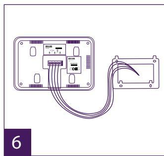
natural_image
Diagram of a device with two connected modules and cable, no text or symbols present
natural_image
Line drawing of a hand holding a handheld device labeled 'PHILIPS' (no text or symbols on the device itself)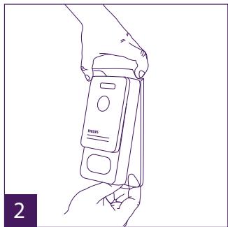
natural_image
Line drawing of a hand holding a handheld electronic device labeled 'PULIS' (no text or symbols on the device itself)
natural_image
Line drawing of hands installing or adjusting a device panel with a tool (no text or symbols visible)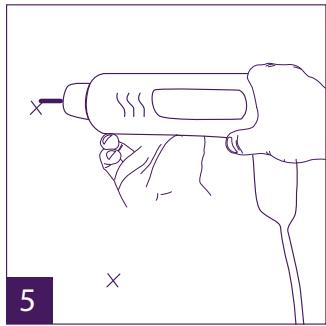
natural_image
Line drawing of a hand holding a handheld tool with a screwdriver (no text or symbols)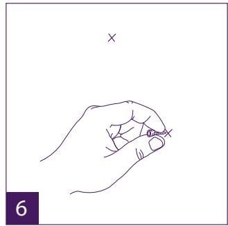
natural_image
Line drawing of a hand holding a pen, with a cross mark above (no text or symbols)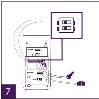

natural_image
Line drawing of a hand using a soldering iron to press a Philips phone (no text or symbols on device)- Wiring.
- Configuring the intercom
- Installing the main or additional monitor
- Installing the main or additional intercom panel
- Installing a camera (optional)
- Get more out of your device
6 TECHNICAL CHARACTERISTICS......p.8
7 ACCESSORIES....p.9
8 TECHNICAL ASSISTANCE - WARRANTY....p.10
9 SAFETY PRECAUTIONS...... p.11
1. SAFETY INSTRUCTIONS

Important!
- Please read the user manual carefully before installing or using this product.
- If you are installing this product for a third party, please remember to leave the manual or a copy of it with the end user.
Warning:
- The various components may only be dismantled by an authorised technician.
Safety precautions:
- To ensure the safe operation of the system, installers, users and technicians must follow all the safety procedures described in this manual.
- Specific warnings and warning symbols are marked on the components where necessary.
2. CONTENTS OF THE KIT

natural_image
Simple line drawing of a monitor with a screen and a horizontal bar labeled 'PHILIPS' (no additional text or symbols)- Monitor 7"
(WelcomeEye Comfort)

natural_image
Line drawing of a monitor with control buttons and a screen (no text or symbols on the device itself)1.bis Monitor 4,3"
(WelcomeEye Compact)

natural_image
Simple line drawing of a rectangular frame with corner holes (no text or symbols)- Wall bracket

natural_image
Simple line drawing of a plug with two wires, no text or symbols present- Plug-in power supply

4. Adaptor for plug-in power supply compatible with EU or UK plug

natural_image
Line drawing of a Philips electronic device with no text or symbols on the body- Intercom panel
3. GENERAL
This videophone consists of an indoor answering unit with a touch screen and an outdoor panel with an intercom and camera, allowing you to see and communicate with the visitor who has pressed the bell. It is easy to install as only two wires are needed for all functions: bell, video image, intercom and strike plate and automatic opener controls.
The WelcomeEye technology allows you to share the intercom panel between 2 families. Each family can own up to 3 monitors.
The system can operate up to one camera and two intercom panels.
To get the most out of your intercom, please read this instruction manual carefully.
The complete instructions can be downloaded at www.philips.com.
4. NOMENCLATURE
Monitor:

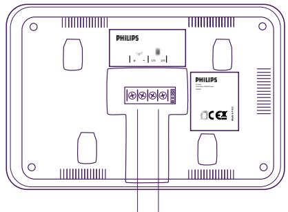
Power supply terminal block
Terminal block for connection to the intercom panel and accessories
Intercom panel
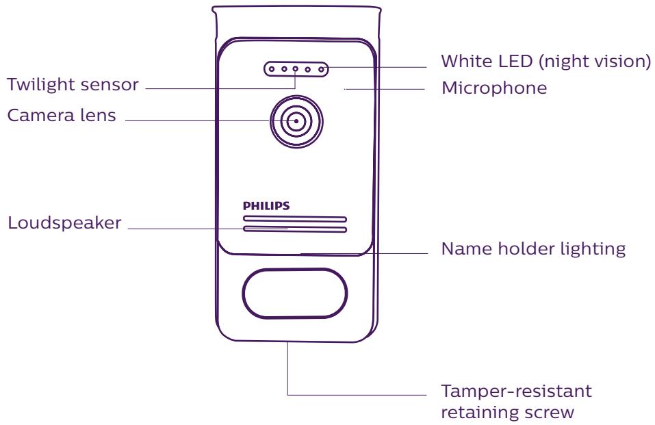
Notes:
- When someone presses the call button, the inside monitor rings and the video is displayed.
- To change the nameplate label, remove the front cover and unclip the plastic cap behind the label.
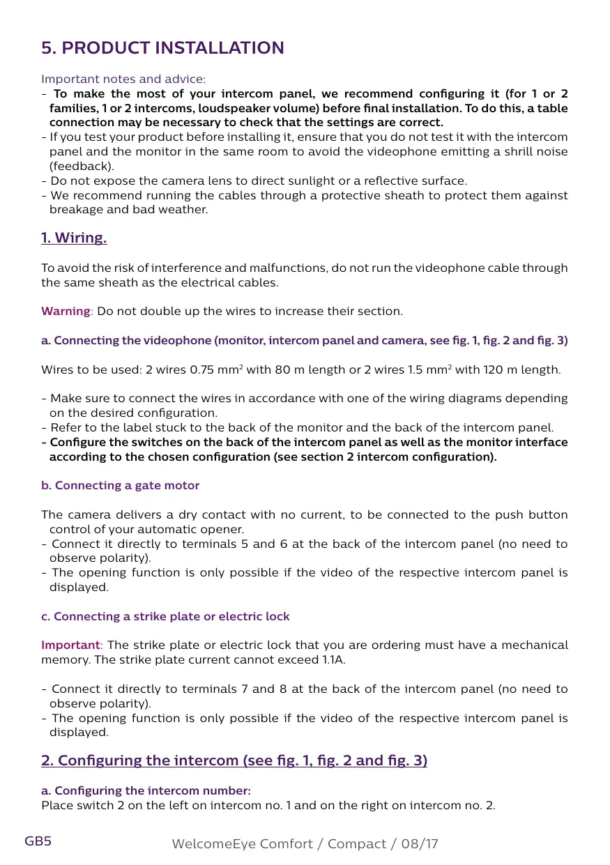
5. PRODUCT INSTALLATION
Important notes and advice:
- To make the most of your intercom panel, we recommend configuring it (for 1 or 2 families, 1 or 2 intercoms, loudspeaker volume) before final installation. To do this, a table connection may be necessary to check that the settings are correct.
- If you test your product before installing it, ensure that you do not test it with the intercom panel and the monitor in the same room to avoid the videophone emitting a shrill noise (feedback).
- Do not expose the camera lens to direct sunlight or a reflective surface.
- We recommend running the cables through a protective sheath to protect them against breakage and bad weather.
1. Wiring.
To avoid the risk of interference and malfunctions, do not run the videophone cable through the same sheath as the electrical cables.
Warning: Do not double up the wires to increase their section.
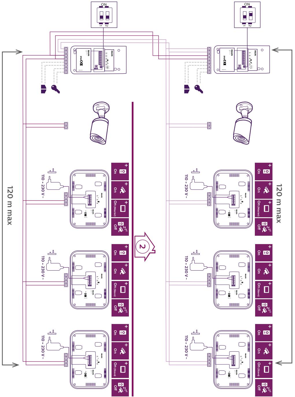
a. Connecting the videophone (monitor, intercom panel and camera, see fig. 1, fig. 2 and fig. 3)
Wires to be used: 2 wires 0.75 mm ^4 with 80 m length or 2 wires 1.5 mm ^2 with 120 m length.
- Make sure to connect the wires in accordance with one of the wiring diagrams depending on the desired configuration.
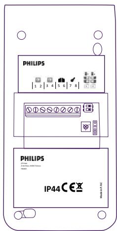
- Refer to the label stuck to the back of the monitor and the back of the intercom panel.
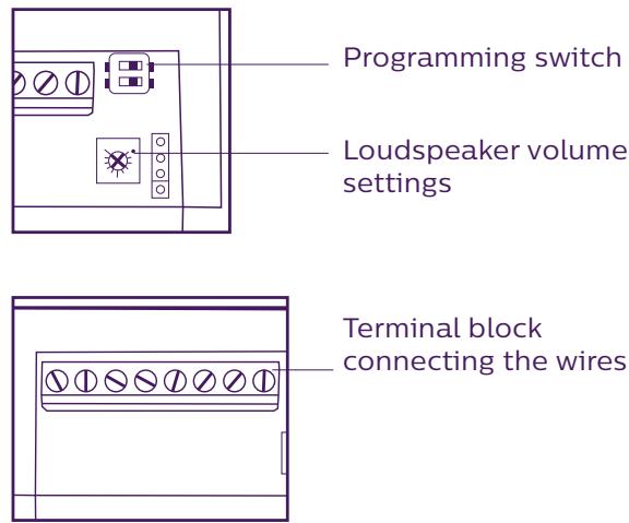
- Configure the switches on the back of the intercom panel as well as the monitor interface according to the chosen configuration (see section 2 intercom configuration).
b. Connecting a gate motor
The camera delivers a dry contact with no current, to be connected to the push button control of your automatic opener.
- Connect it directly to terminals 5 and 6 at the back of the intercom panel (no need to observe polarity).
- The opening function is only possible if the video of the respective intercom panel is displayed.
c. Connecting a strike plate or electric lock
Important: The strike plate or electric lock that you are ordering must have a mechanical memory. The strike plate current cannot exceed 1.1A.
- Connect it directly to terminals 7 and 8 at the back of the intercom panel (no need to observe polarity).
- The opening function is only possible if the video of the respective intercom panel is displayed.
2. Configuring the intercom (see fig. 1, fig. 2 and fig. 3)
a. Configuring the intercom number:
Place switch 2 on the left on intercom no. 1 and on the right on intercom no. 2.
b. Configuring the number of families:
Place switch 1 on the left to be in one-family mode and on the right to be in 2-family mode.
c. Intercom volume settings:
Turn the volume control with a Phillips head screwdriver to adjust the intercom volume.
3. Installing the main or additional monitor
natural_image
Line drawing of a hand holding a small electronic component with a screwdriver (no text or symbols)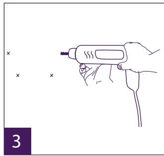
natural_image
Line drawing of a hand holding a tool with a probe, no text or symbols present
natural_image
Simple line drawing of a hand holding a small object, with two small 'x' marks nearby (no text or symbols)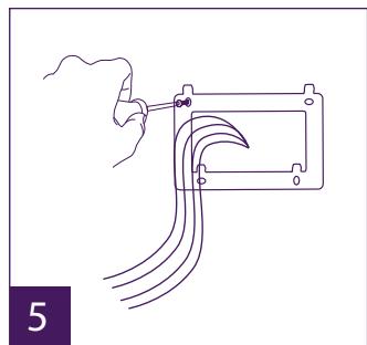
natural_image
Line drawing of a hand holding a tool next to a rectangular device with multiple curved wires (no text or symbols)
natural_image
Diagram of a device with two connected modules and cable, no text or symbols present
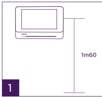
1 - Position the wall bracket so that the screen of the monitor is approximately 1.60m above the ground.
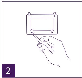
2 - Mark the location of the holes using the U bolt.
3 - Drill.
4 - Use pegs adapted to the bracket (those supplied are suitable for solid walls).
5 - Attach the wall bracket.
6 - Connect the 2 intercom panel wires and the 2 power supply wires in accordance with the wiring diagram.
7 - Position the monitor on the wall bracket.
8 - Depending on the configuration selected, and when wiring is completed, the interface may have to be configured. For more information please refer to the complete
instructions which can be downloaded at www.philips.com.

Warning: during this step, do not connect the power supply to the 230V AC
4. Installing the main or additional intercom panel
Warning: The product must not be connected to the power supply before wiring is complete.
natural_image
Line drawing of a hand holding a Philips handheld device with a screwdriver inserted (no text or symbols)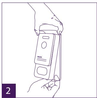
natural_image
Line drawing of a hand holding a handheld electronic device (no text or symbols visible)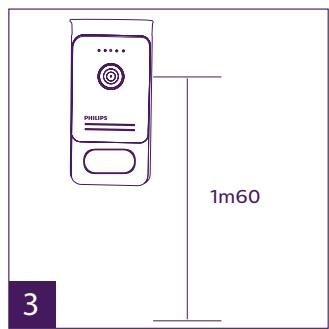

natural_image
Line drawing of hands installing or adjusting a device panel (no text or symbols visible)
natural_image
Line drawing of a hand holding a handheld tool with a screwdriver (no text or symbols)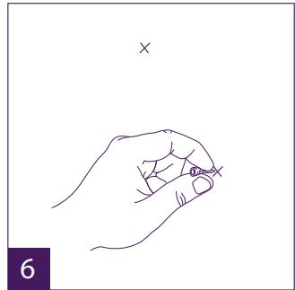
natural_image
Line drawing of a hand holding a small object with an 'x' mark above, no text or symbols present

natural_image
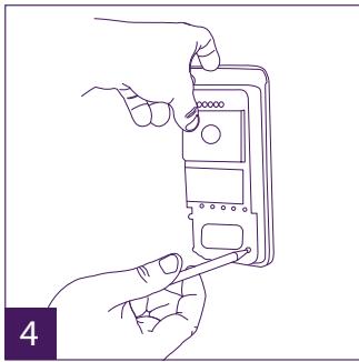
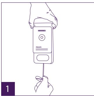
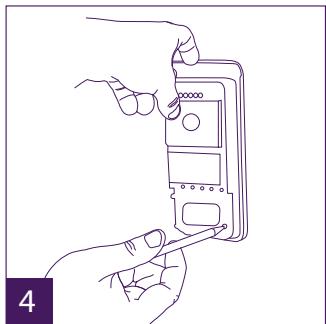
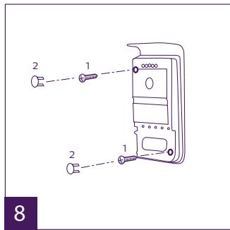
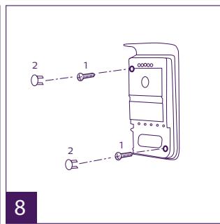
Line drawing of a hand using a power tool to press a handheld device labeled 'PHILIPS' (no text or symbols on the device itself)1 - Remove the tamper-resistant screw from the intercom panel.
2 - Tip the intercom panel cover forward.
3 – The intercom's lens should be approximately 1.60m above the ground.
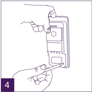
4 - Mark the locations.
5 - Drill.
6 - Use pegs adapted to the nature of the support (the screws supplied are suitable for solid walls).
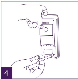
7 - Connect the two wires from the monitor and, if necessary, connect the electric strike
plate and the gate (see section 1. Wiring). Configure the switches at the back of the intercom panel (see section 2. Configuring the intercom).
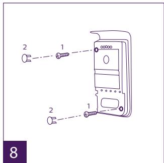
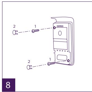
8 – Insert the screws and refit the two caps concealing the retaining screws.
Note: screw through the black covers on the back of the intercom panel – do not remove them.
9 - Refit the front cover of the intercom and tighten the tamper-resistant retaining screw.
10 - Connect the 230V AC power supply to the modular adaptor, for an installation compliant with applicable standards (NFC 15-100 in France).
- Verify the smooth functioning (video call, etc.).
- When there is a second intercom panel, don't forget to configure the monitor(s).

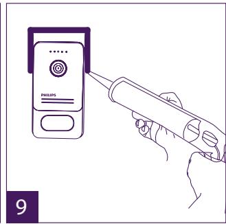
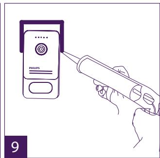
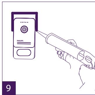
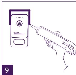
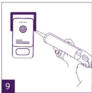
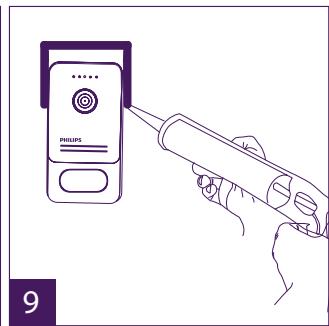
11 - Attach a silicone seal* between the shield and the wall to stop flowing water. *Do not use acetic acid-based silicone (vinegar odour).
5. Installing a camera (optional)
Connect the wires in accordance with the wiring diagram.
Choose a suitable place to install the camera.
Ensure that nothing gets in the way of the installation.
Screw the wall section with the screws provided (for solid walls).
Point the camera in the desired direction and tighten the retainer screw.
Configure the monitor(s)

6. Get more out of your device
To find out more about your Philips WelcomeEye product, you can download the complete instructions at www.philips.com.
6. TECHNICAL CHARACTERISTICS
Monitor:
ref.: 531003 (WelcomeEye Comfort)
ref.: 531005 (WelcomeEye Compact)
- 2 wires
- 7" screen (Comfort), 4.3" screen (Compact)
- Resolution 800 x 480 (Comfort), 480 x 272 (Compact)
- Current consumption: 460mA (Comfort), 400mA (Compact)
- Power consumption: 11.1W (Comfort), 9.6W (Compact)
- 6 chimes (85dB)
- Dimensions: 142(h) x 210(l) x 15(d) (Comfort), 116(h) x 146(l) x 16(d) (Compact)
Intercom panel
ref.: 538200
- C-MOS colour sensor 900TVL
- Viewing angle H100° / V75°
- Night vision (white Leds)
- Strike plate control 12V/1.1A
- Gate control: breaking capacity 12V/2A
- IP44
- Operating temperature: -20^ / +50^
WelcomeEye Outdoor (additional intercom panel)
ref.: 531006
- C-MOS colour sensor 900TVL
- Viewing angle H130° / V 90°
- Night vision (white Leds)
- Strike plate control 12V/1.1A
- Gate control: breaking capacity 12V/2A
- RFID (125kHz)
- IP44
- operating temperature: -20^ / +50^
- Dimensions: 168 (h) x 82 (w) x 38 (d)
WelcomeEye AddComfort (additional monitor)
ref.: 531003
- 2 wires
- 7" screen
- Resolution 800 x 480
- Current consumption: 460mA
- Power consumption: 11.1W
- 6 chimes (85dB)
- Dimensions: 142 (h) x 210 (w) x 15 (d)
WelcomeEye AddCompact (additional monitor)
ref.: 531005
- 2 wires
- 4.3" screen
- 480 x 272 Resolution
- Current consumption: 400mA
- Power consumption: 9.6W
- 6 chimes (85dB)
- Dimensions: 116 (h) x 146 (l) x 16 (d)
WelcomeEye Cam (additional camera)
ref.: 531007
- C-MOS colour sensor 900TVL
- viewing angle: H95° / V75°
- operating temperature: -20^ / +50^
- protection index: IP66
7. ACCESSORIES
WelcomeEye AddCompact - DES 9300 DDE (ref.: 531005)*
WelcomeEye AddComfort - DES 9500 DDE (ref.: 531003)*
WelcomeEye Cam - DES 9900 CVC (ref.: 531007).
WelcomeEye Outdoor - DES 9900 VOS (ref.: 531006)**
WelcomeEye Lock - DES 1000 EDL (ref.: 531008).
WelcomeEye Lock - DES 1100 EDL (ref.: 531009).
WelcomeEye Power - DES 1000 DPS (ref.: 531010)**
WelcomeEye TAG - DES 1000 ACI (ref.: 531011)**
** Refer to the complete WelcomeEye Connect/Touch instructions available on the www.philips.com website for more information.
* Refer to the complete WelcomeEye Comfort/Compact instructions available on the www.philips.com website for more information.
8. TECHNICAL ASSISTANCE - WARRANTY
FAQs are available in the complete instructions which can be downloaded at www.philips.com.
This product is guaranteed for parts and labour in our workshops.
The warranty does not cover: consumables (batteries, etc.) and damage caused by misuse, improper use, improper installation, external intervention, damage due to physical or electrical shocks, dropping, or atmospheric phenomena.
- Do not open the device, as this will void the warranty.
- If the unit is returned for After Sales Service, protect the unit to prevent scratches.
- Clean with a soft cloth only, no solvents. The guarantee is void if parts have been dismantled. Before cleaning it, disconnect the equipment or switch it off at the mains.
Warning: Do not use any gasoline or carboxylic acid, alcohol or similar treatment. In addition to damaging your device, the fumes are also hazardous to your health and are explosive.
Do not use any tool that can conduct voltage (wire brush or other sharp tool, etc.) for cleaning.
The till receipt or invoice is your proof of purchase date.
If necessary, the contacts and opening hours of our technical assistance centres are available on the www.philips.com website.
WARRANTY CARD
Mr / Mrs : ____
Phone number: ____
Address : ____
E-mail : ____
Date of purchase : ____/____/____ (DD/MM/YYYY)
Dealer : ____
Dealer Phone : ____
Dealer address : ____
Serial number PHI/1031/
Important: Please keep this warranty card with your proof of purchase.
Philips and Philips' shield emblem are registered trademarks of Koninklijke Philips N.V. and are used under licence. This product has been manufactured by and is sold under the
responsibility of CFI Extel SAS, and CFI Extel SAS is the sole guarantor of this product.
9. SAFETY PRECAUTIONS
Any damage caused by a failure to adhere to the manual shall void the warranty. We assume no liability for damages resulting therefrom!
We cannot be held responsible for any damage to property or persons caused by incorrect use or a failure to adhere to the safety instructions.
This product has been manufactured in full compliance with safety instructions. In order to maintain this status and get the most out of the product, users must adhere to the safety instructions and warnings contained in this manual.
⚠: This symbol indicates that there is a risk of electric shock or short-circuit.
- You should only use this product with a voltage between: 100-240 Volts and 50-60 hertz. Never attempt to use this device with a different voltage.
- Ensure that all the system's electrical connections conform to the instructions for use.
- In commercial establishments, ensure that you adhere to the electrical installation accident prevention regulations.
- In schools, training facilities, workshops, etc. qualified personnel must be on hand to monitor electronic equipment operation.
- You must follow the instructions for use of any other devices connected to the system.
- Please contact an experienced person if you have any doubts regarding equipment operation or safety.
- Never plug in or unplug electrical equipment with wet hands.
- When installing this product, check that the power supply cables are not at risk of being damaged.
- Never replace damaged electrical cables yourself! In this case, remove them and call an expert.
- The mains supply should be located close to the device and must be easily accessible.
- An easily accessible cut-off system (switch disconnector, circuit breaker, equivalent system) must be integrated into the building's wiring installation for the equipment connected to the power grid.
- Keep a minimum distance around the device to guarantee sufficient ventilation.
- Ventilation should not be blocked by covering the ventilation opening with an object such as a newspaper, tablecloth or curtain, etc.).
- No open flame source such as a burning candle must be placed on the device.
- Respect the product's operating temperature.
- The device must not be exposed to liquid flow or splashing. Do not place any objects filled with liquid such as vases on the device.
INHALT
1 SICHERHEITSANWEISUNGEN....S. 2
2 INHALT DES SETS S. 2
3 ALLGEMEINES....S. 3
4 NOMENKLATUR....S. 3
5 INSTALLATION DES PRODUKTS....S. 5
natural_image
Simple line drawing of a tablet device with no text or symbols on the screen or body- Monitor 7" (WelcomeEye Comfort)

natural_image
Line drawing of a monitor with control buttons at the bottom (no text or symbols on the device itself)1.bis Monitor 4,3" (WelcomeEye Compact)

natural_image
Simple line drawing of a rectangular frame with corner holes (no text or symbols)- Wandhalterung

natural_image
Simple line drawing of a plug with two wires, no text or symbols present- Netzteilstecker
natural_image
Line drawing of a Philips electronic device with no visible text or symbols on the body- Türsprechanlage
3. ALLGEMEINES
natural_image
Line drawing of a hand holding a small electronic component (no text or symbols)
natural_image
Line drawing of a hand holding a handheld tool, with no text or symbols present
natural_image
Simple line drawing of a hand holding a small object, with three small 'x' marks nearby (no text or symbols)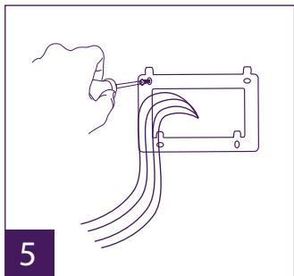
natural_image
Line drawing of a hand using a tool to connect wires into a rectangular device (no text or symbols)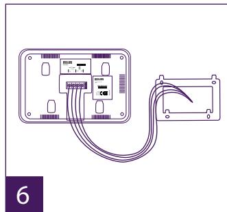
natural_image
Diagram of a device with two connected modules and cable, no text or symbols present
natural_image
Line drawing of a hand holding a handheld device with a screen, no text or symbols present
natural_image
Line drawing of a hand holding a handheld device labeled 'PULS' (no text or symbols on the device itself)

natural_image
Line drawing of hands installing or adjusting a device panel with a tool (no text or symbols visible)
natural_image
Line drawing of a hand holding a handheld tool with a screwdriver (no text or symbols)
natural_image
Line drawing of a hand holding a pen, with a cross mark above (no text or symbols)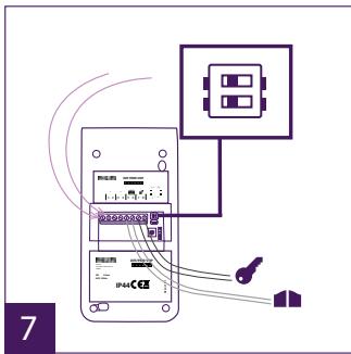


natural_image
Line drawing of a hand using a soldering iron to press a Philips phone (no text or symbols on device)natural_image
Simple line drawing of a monitor with a screen and a label 'PHILIPS' below it (no other text or symbols)- Scherm 7" (WelcomeEye Comfort)

natural_image
Line drawing of a Philips monitor with control buttons (no text or symbols on the device itself)1.bis Scherm 4,3" (WelcomeEye Compact)

natural_image
Simple line drawing of a rectangular frame with corner holes (no text or symbols)- Wandhouder

natural_image
Simple line drawing of a plug with two wires, no text or symbols present- Inplugbare voeding
natural_image
Line drawing of a Philips electronic device with no text or symbols on the body- Straatunit
3. ALGEMEEN
5. INSTALLATIE VAN HET PRODUCT
natural_image
Line drawing of a hand holding a small electronic component with a screwdriver (no text or symbols)
natural_image
Line drawing of a hand holding a tool with a probe, no text or symbols present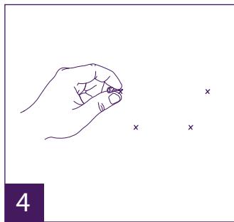
natural_image
Simple line drawing of a hand holding a small object with three small 'x' marks nearby (no text or symbols)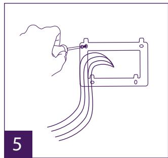
natural_image
Line drawing of a hand holding a tool next to a mechanical component with multiple wires (no text or symbols)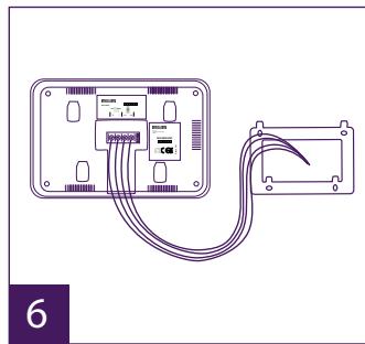
natural_image
Diagram of a device with two connected modules and cable, no text or symbols present
natural_image
Line drawing of a hand holding a Philips phone with a screwdriver inserted (no text or symbols)
natural_image
Line drawing of a hand holding a handheld electronic device (no text or symbols visible)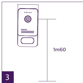
natural_image
Line drawing of hands installing or adjusting a device panel (no text or symbols)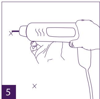
natural_image
Line drawing of a hand holding a handheld tool with a screwdriver (no text or symbols)
natural_image
Line drawing of a hand holding a small object with an 'x' mark above, no text or symbols present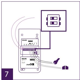
natural_image
Line drawing of a hand using a soldering iron to press a Philips phone (no text or symbols on device)ref: 531003 (WelcomeEye Comfort)
ref: 531005 (WelcomeEye Compact)
- 2 draden
- Scherm 7" (Comfort), 4,3" (Compact)
- Resolutie 800 x 480 (Comfort), 480 x w272 (Compact)
- Stroomverbruik: 460mA (Comfort), 400mA (Compact)
- Verbruikt vermogen: 11,1W (Comfort), 9,6W (Compact)
- 6 beltonen (85dB)
- Afmetingen: 142(h) x 210(l) x 15(d) (Comfort), 116(h) x 146(l) x 16(p) (Compact)
Straatunit:
ref: 538200
natural_image
Simple line drawing of a rectangular device with a screen and label 'PHILIPS' at the bottom (no other text or symbols)- Monitor 7"
(WelcomeEye Comfort)

natural_image
Simple line drawing of a monitor with control buttons at the bottom (no text or symbols on the device itself)1.bis Monitor 4,3"
(WelcomeEye Compact)

natural_image
Simple line drawing of a rectangular frame with mounting holes (no text or symbols)- Uchwyt ścienny

natural_image
Simple line drawing of a plug with two wires (no text or symbols)natural_image
Line drawing of a Philips electronic device with no visible text or symbols on the body- Panel zewnętrzny
3. INFORMACJE OGÓLNE
natural_image
Line drawing of a hand holding a screwdriver inside a rectangular frame (no text or symbols)
natural_image
Line drawing of a hand holding a tool with a probe, no text or symbols present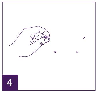
natural_image
Line drawing of a hand holding a small object with three small 'x' marks nearby (no text or symbols)
natural_image
Line drawing of a hand using a tool to cut or wire through a mechanical component (no text or symbols)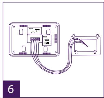
natural_image
Diagram of a device with two connected modules and cable, no text or symbols present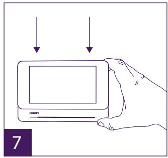
natural_image
Line drawing of a hand holding a handheld device with a button labeled 'PHOLOS' (no text or symbols on the device itself)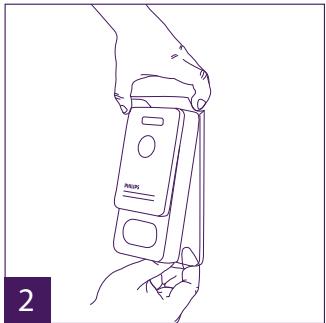
natural_image
Line drawing of a hand holding a handheld electronic device (no text or symbols visible)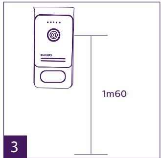
natural_image
Line drawing of hands installing or adjusting a device panel with a tool (no text or symbols visible)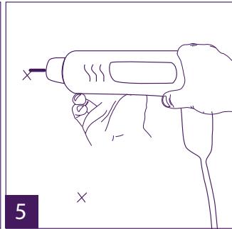
natural_image
Line drawing of a hand holding a handheld electric drill pen (no text or symbols)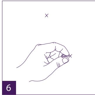
natural_image
Line drawing of a hand holding a small object with an 'x' mark above, no text or symbols present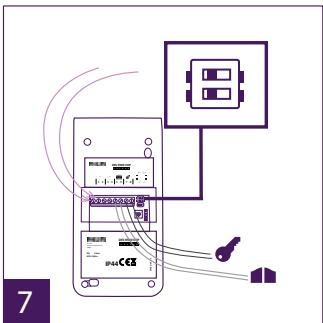
natural_image
Line drawing of a hand using a soldering iron to press a Philips phone (no text or symbols on device)natural_image
Simple line drawing of a monitor with a screen and a pointer labeled 'PHILIPS' (no additional text or symbols)- Monitor 7" (WelcomeEye Comfort)

natural_image
Simple line drawing of a monitor with a screen and control buttons at the bottom (no text or symbols on the device itself)1.bis Monitor 4,3" (WelcomeEye Compact)

natural_image
Simple line drawing of a rectangular frame with corner holes (no text or symbols)- Supporto murale

natural_image
Simple line drawing of a plug with two wires, no text or symbols present- Spina alimentazione
natural_image
Line drawing of a Philips electronic device with control panel and buttons (no text or symbols)- Pulsantiera esterna
natural_image
Line drawing of a hand holding a small electronic component with a screwdriver (no text or symbols)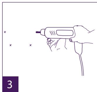
natural_image
Line drawing of a hand holding a handheld tool, with no text or symbols present
natural_image
Simple line drawing of a hand holding a small object with three small 'x' marks nearby (no text or symbols)
natural_image
Line drawing of a hand holding a tool next to a rectangular device with curved wires (no text or symbols)
natural_image
Diagram of a device with two connected modules and cable, no text or symbols present
natural_image
Line drawing of a hand holding a handheld electronic device labeled 'PHILIPS', with no visible text or symbols on the device itself.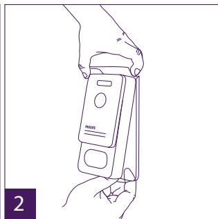
natural_image
Line drawing of a hand holding a device with a screen, no text or symbols present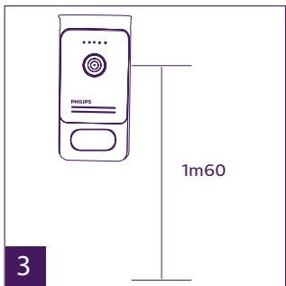

natural_image
Line drawing of hands installing or adjusting a device panel (no text or symbols visible)
natural_image
Line drawing of a hand holding a handheld electric drill pen (no text or symbols)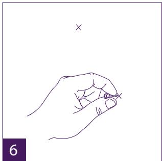
natural_image
Line drawing of a hand holding a small object, with no text or symbols present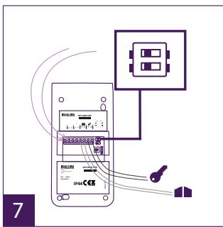
flowchart
graph TD
    A["Device"] --> B["Switch"]
    B --> C["Control Panel"]
    C --> D["IP44CE5"]
    D --> E["Switch"]
    E --> F["Control Panel"]
    F --> G["IP44CE5"]
    style A fill:#f9f,stroke:#333
    style B fill:#ccf,stroke:#333
    style C fill:#cfc,stroke:#333
    style D fill:#fcc,stroke:#333
    style E fill:#cff,stroke:#333
    style F fill:#ffc,stroke:#333
    style G fill:#cfc,stroke:#333
natural_image
Line drawing of a hand using a power tool to press a Philips phone (no text or symbols on the device)natural_image
Simple line drawing of a monitor with a screen and a pointer labeled 'PHILIPS' (no additional text or symbols)- Monitor 7"
(WelcomeEye Comfort)

natural_image
Line drawing of a Philips tablet device with control buttons (no text or symbols on the device itself)1.bis Monitor 4,3"
(WelcomeEye Compact)

natural_image
Simple line drawing of a rectangular frame with corner holes (no text or symbols)- Soporte de pared

natural_image
Simple line drawing of a plug with two wires, no text or symbols presentnatural_image
Line drawing of a Philips electronic device with no text or symbols on the body- Placa externa
3. GENERALIDADES
natural_image
Line drawing of a hand holding a screwdriver inside a rectangular frame (no text or symbols)
natural_image
Line drawing of a hand holding a handheld tool, with no text or symbols present
natural_image
Simple line drawing of a hand holding a small object near three small 'x' marks (no text or symbols)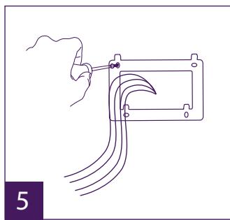
natural_image
Line drawing of a hand holding a tool next to a mechanical component with multiple curved wires (no text or symbols)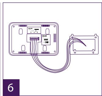
natural_image
Diagram of a device with connected cables showing internal components (no text or symbols)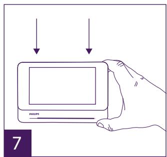
natural_image
Line drawing of a hand holding a digital card with an LCD screen, no text or symbols presentnatural_image
Line drawing of a hand holding a handheld device labeled 'PHILIPS' (no text or symbols on the device itself)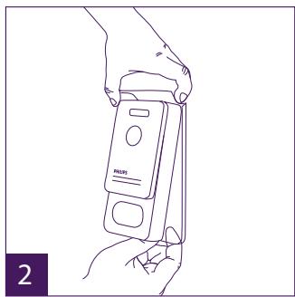
natural_image
Line drawing of a hand holding a handheld device labeled 'FAIRI' (no text or symbols on the device itself)

natural_image
Line drawing of hands installing or adjusting a device panel with a tool (no text or symbols visible)
natural_image
Line drawing of a hand holding a handheld tool with a screwdriver (no text or symbols)
natural_image
Line drawing of a hand holding a pen, with a cross mark above (no text or symbols)

natural_image
Line drawing of a hand using a power tool to press a Philips phone (no text or symbols on device)natural_image
Simple line drawing of a monitor with a screen and a pointer labeled 'PHILIPS' (no additional text or symbols)- Monitor 7"
(WelcomeEye Comfort)

natural_image
Line drawing of a Philips electronic device with control buttons (no text or symbols on the device itself)1.bis Monitor 4,3"
(WelcomeEye Compact)

natural_image
Simple line drawing of a rectangular frame with corner holes (no text or symbols)- Suporte de parede

natural_image
Simple line drawing of a plug with two wires, no text or symbols present- Transformador
natural_image
Line drawing of a Philips electronic device with control panel and buttons (no text or symbols on body)- Placa de rua
3. GENERALIDADE
natural_image
Line drawing of a hand holding a screwdriver inside a rectangular frame (no text or symbols)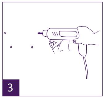
natural_image
Line drawing of a hand holding a tool with a probe, no text or symbols present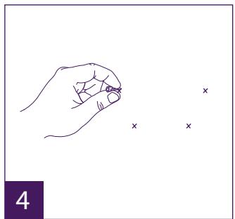
natural_image
Simple line drawing of a hand holding a small object with three small 'x' marks nearby (no text or symbols)
natural_image
Line drawing of a hand using a tool to cut or wire through a mechanical component (no text or symbols)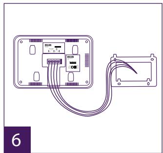
natural_image
Diagram of a device with two connected modules and cable, no text or symbols present
natural_image
Line drawing of a hand holding a Philips smartphone with a screwdriver inserted (no text or symbols)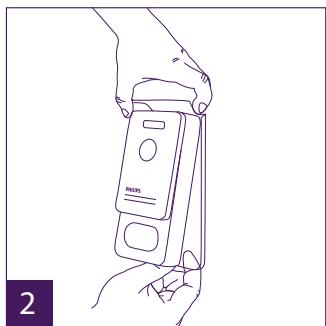
natural_image
Line drawing of a hand holding a handheld device with a label 'PULF' on its screen (no text or symbols on the device itself)
natural_image
Line drawing of hands installing or adjusting a device panel with a tool (no text or symbols visible)
natural_image
Line drawing of a hand holding a handheld electric drill pen (no text or symbols)
natural_image
Line drawing of a hand holding a pen, with an 'x' mark above (no text or symbols on the diagram itself)

natural_image
Line drawing of a hand using a power tool to press a Philips phone into a wall (no text or symbols on the device itself)ref: 531003 (WelcomeEye Comfort)
ref: 531005 (WelcomeEye Compact)
- 2 fios
- Ecrã 7" (Comfort), 4,3" (Compact)
GB - Don't throw batteries or out of order products with the household waste (garbage). The dangerous substances that they are likely to include may harm health or the environment. Make your retailer take back these products or use the selective collect of garbage proposed by your city. Directive WEEE 2012/19/EU
GB - This symbol indicates that the device must only be installed and used indoors
GB - The protection of devices bearing this symbol is guaranteed by double insulation, they do not require a safety connection to electrical earth.
GB - Alternating Current
D - Wechselstrom
NL - Gelijkstroom
PL - Prąd zmienny