
P1367-E - IP Surveillance Camera AXIS - Free user manual and instructions
Find the device manual for free P1367-E AXIS in PDF.
| Product type | IP surveillance camera |
| Brand | AXIS |
| Model | P1367-E |
| Power supply | PoE IEEE 802.3af/802.3at Type 1 Class 3 |
| Power consumption | Max. 9.2 W, typical 5.3 W |
| Operating temperature | -40 °C to 55 °C (max intermittent 60 °C) |
| Relative humidity | 10 to 100 % (condensing) |
| Local storage | Slot for microSD/microSDHC/microSDXC card (not included) |
| Network connectivity | Shielded RJ45 Ethernet with PoE |
| Audio | Mono microphone input (3.5 mm), line output (3.5 mm) |
| Inputs/Outputs | 4-pin I/O connector: 1 configurable digital input, 1 configurable digital output, 12 V DC 50 mA power |
| Serial interface | RS485/RS422 (2 blocks of 2 pins) |
| Protection rating | IK10 (impact resistance) |
| Focus | Autofocus with focus assistant |
| Zoom | Varifocal lens, manual control |
| Corridor format | Rotation of the optical unit possible |
| Installation | Wall mount included, fixing with Torx screws |
| Maintenance and cleaning | Clean cloth dampened with pure water; do not use chemicals |
| Security | Intrusion alarm, motion detection, event trigger; use shielded network cable (STP) |
| Spare parts and repairability | Replaceable CR2032 lithium battery (contact support); do not repair yourself |
| Transport | Original packaging recommended |
| Compliance | CAN ICES-3 (Class A) |
| Installation software | AXIS IP Utility, AXIS Camera Management (free) |
| Indicators | Status (green/orange/red), network (green/orange/off), power (green/orange) |
Frequently Asked Questions - P1367-E AXIS
User questions about P1367-E AXIS
0 question about this device. Answer the ones you know or ask your own.
Ask a new question about this device
Download the instructions for your IP Surveillance Camera in PDF format for free! Find your manual P1367-E - AXIS and take your electronic device back in hand. On this page are published all the documents necessary for the use of your device. P1367-E by AXIS.
USER MANUAL P1367-E AXIS
AXIS P1367-E Network Camera
English EN
France:Francais FR
Deutschland: Deutsch DE
Italy: Italiano IT
Espana: Espanol ES
日本:日本語 JA
中文:简体中文 ZH
Legal considerations
Video and audio surveillance can be regulated by laws that vary from country to country. Check the laws in your local region before using this product for surveillance purposes.
This product includes the following licences:
one (1) AAC decoder license
one (1) H.264 decoder license
To purchase further licenses, contact your reseller.
Liability
Every care has been taken in the preparation of this document. Please inform your local Axis office of any inaccuracies or omissions. Axis Communications AB cannot be held responsible for any technical or typographical errors and reserves the right to make changes to the product and manuals without prior notice. Axis Communications AB makes no warranty of any kind with regard to the material contained within this document, including, but not limited to, the implied warranties of merchantability and fitness for a particular purpose. Axis Communications AB shall not be liable nor responsible for incidental or consequential damages in connection with the furnishing, performance or use of this material. This product is only to be used for its intended purpose.
Intellectual property rights
Axis AB has intellectual property rights relating to technology embodied in the product described in this document. In particular, and without limitation, these intellectual property rights may include one or more of the patents listed at www-axis.com/patent.htm and one or more additional patents or pending patent applications in the US and other countries.
This product contains licensed third-party software. See the menu item "About" in the product's user interface for more information.
This product contains source code copyright Apple Computer, Inc., under the terms of Apple Public Source License 2.0 (see www.opensource.apple.com/aps/). The source code is available from https://developer.apple.com/bonjour/
Equipment modifications
This equipment must be installed and used in strict accordance with the instructions given in the user documentation. This equipment contains no user-serviceable components. Unauthorized equipment changes or modifications will invalidate all applicable regulatory certifications and approvals.
Trademark acknowledgments
AXIS COMMUNICATIONS, AXIS and VAPIX are registered trademarks or trademark applications of Axis AB in various jurisdictions. All other company names and products are trademarks or registered trademarks of their respective companies.
Apple, Boa, Apache, Bonjour, Ethernet, Internet Explorer, Linux, Microsoft, Mozilla, Real, SMPTE, QuickTime, UNIX, Windows, Windows Vista and WWW are registered trademarks of the respective holders. Java and all Java-based trademarks and logos are trademarks or registered trademarks of Oracle and/or its affiliates. UPnP™ is a certification mark of the UPnP™ Implementers Corporation.
SD, SDHC and SDXC are trademarks or registered trademarks of SD-3C, LLC in the United States, other countries or both. Also, miniSD, microSD, miniSDHC, microSDHC, microSDXC are all trademarks or registered trademarks of SD-3C, LLC in the United States, other countries or both.
Regulatory information
Europe
CE This product complies with the applicable CE marking directives and harmonized standards:
Electromagnetic Compatibility (EMC) Directive 2014/30/EU. See Electromagnetic compatibility (EMC) 4.
Low Voltage (LVD) Directive 2014/35/EU. See Safety 5.
- Restrictions of Hazardous Substances (RoHS) Directive 2011/65/EU. See Disposal and recycling 5.
A copy of the original declaration of conformity may be obtained from Axis Communications AB. See Contact information 5.
Electromagnetic compatibility (EMC)
This equipment has been designed and tested to fulfill applicable standards for:
- Radio frequency emission when installed according to the instructions and used in its intended environment.
- Immunity to electrical and electromagnetic phenomena when installed according to the instructions and used in its intended environment.
USA
This equipment has been tested using an unshielded network cable (UTP) and found to comply with the limits for a Class A digital device, pursuant to part 15 of the FCC rules. This equipment has also been tested using a shielded network cable (STP) and found to comply with the limits for a Class A digital device, pursuant to part 15 of the FCC rules. These limits are designed to provide reasonable protection against harmful interference when the equipment is operated in a commercial environment. This equipment generates, uses, and can radiate radio frequency energy and, if not installed and used in accordance with the instruction manual, may cause harmful interference to radio communications. Operation of this equipment in a residential area is likely to cause harmful interference in which case the user will be required to correct the interference at his own expense.
Canada
This digital equipment fulfills the requirements for RF emission according to the Class A limit of EN 55032. The product shall be connected using a shielded network cable (STP) that is properly grounded. Notice! This is a Class A product. In a domestic environment this product may cause RF interference, in which case the user may be required to take adequate measures.
This product fulfills the requirements for immunity according to EN 61000-6-1 residential, commercial and light-industrial environments.
This product fulfills the requirements for immunity according to EN 61000-6-2 industrial environments.
This product fulfills the requirements for immunity according to EN 55024 office and commercial environments.
Australia/New Zealand
This digital equipment fulfills the requirements for RF emission according to the Class A limit of AS/NZS CISPR 32.
The product shall be connected using a shielded network cable (STP) that is properly grounded. Notice! This is a Class A product. In a domestic environment this product may cause RF interference, in which case the user may be required to take adequate measures.
Japan
This product complies with IEC/EN/UL 62368-1, safety of audio/video and IT equipment, and IEC/EN/UL 60950-22, Safety of Information Technology Equipment. The product shall be grounded either through a shielded network cable (STP) or other appropriate method.
Disposal and recycling
When this product has reached the end of its useful life, dispose of it according to local laws and regulations. For information about your nearest designated collection point, contact your local authority responsible for waste disposal. In accordance with local legislation, penalties may be applicable for incorrect disposal of this waste.
Europe

This symbol means that the product shall not be disposed of together with household or commercial waste. Directive 2012/19/EU on waste electrical and electronic equipment (WEEE) is applicable in the European Union member states. To prevent potential harm to human health and the environment, the product must be disposed of in an approved and environmentally safe recycling process. For information about your nearest designated collection point, contact your local authority responsible for waste disposal. Businesses should contact the product supplier for information about how to dispose of this product correctly. This product complies with the requirements of Directive 2011/65/EU on the restriction of the use of certain hazardous substances in electrical and electronic equipment (RoHS).
China

This product complies with the requirements of
SJ/T 11364-2014, Marking for the restriction of hazardous substances in electrical and electronic products.
Axis Communications AB
Emdalavagen 14
223 69 Lund
Sweden
Tel: +46 46 272 1800
Fax: +46 46 13 61 30
www-axis.com
Warranty information
For information about Axis' product warranty and thereto related information, go to www-axis.com/warranty/
Support
Should you require any technical assistance, please contact your Axis reseller. If your questions cannot be answered immediately, your reseller will forward your queries through the appropriate channels to ensure a rapid response. If you are connected to the Internet, you can:
- download user documentation and software updates
find answers to resolved problems in the FAQ database. Search by product, category, or phrase - report problems to Axis support staff by logging in to your private support area
chat with Axis support staff - visit Axis Support at www-axis.com/support
Learn more!
Visit Axis learning center www-axis.com/academy/ for useful trainings, webinars, tutorials and guides.
Package contents 11
Product overview 12
How to install the product 14
Install the hardware 14
How to access the product 20
How to adjust focus and zoom 21
How to adjust focus with the Focus Assistant 21
How to reset to factory default settings 23
Further information 24
Optional accessories 24
Technical specifications 25
SD card slot 26
Buttons 26
Connectors 26
Operating conditions 29
Power consumption 29
Safety information 31
Hazard levels 31
Other message levels 31
Safety instructions 32
Transportation 32
Battery 32
AXIS P1367-E Network Camera
4-pin I/O connector block for connecting external devices
2-pin RS485/422 connector block (x2)
- Wall mount
Torx screwdriver T20
- Torx screwbit T30
- Mounting tool for RJ45
- IK10 tool
Desiccant bag
Printed materials
Installation Guide (this document)
- Extra serial number label (2x)
- AVHS Authentication key
Product overview
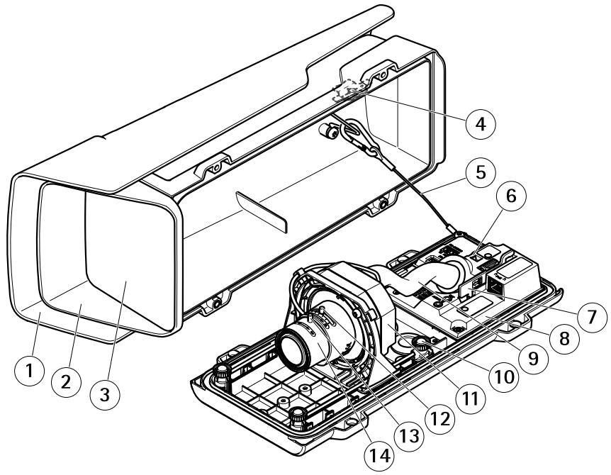
1 Weather shield
2 Top cover
3 Window
4 Intrusion alarm magnet
5 Safety wire
6 Cable tie anchor
7 IK10 tool
8 Intrusion alarm sensor
9 Cable cover
10 Spring loaded thumb screw (4x)
11 Optic unit
12 Zoom puller
13 Lock screw for focus ring
14 Focus ring
NOTICE
Do not lift the product in the cable cover.
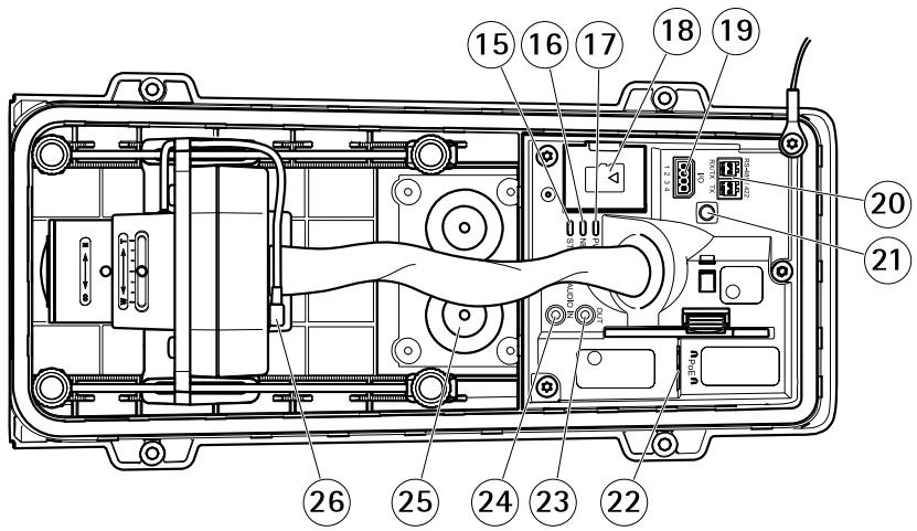
15 Status LED
16 Network LED
17 Power LED
18 microSD card slot
19 I/O connector
20 RS485/422 connector
21 Control button
22 Network connector (PoE)
23 Audio out
24 Audio in
25 Cable gasket M20 (2x)
26 Iris connector
How to install the product
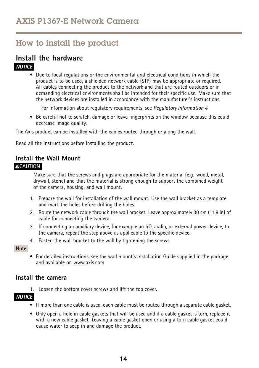
Install the hardware
NOTICE
- Due to local regulations or the environmental and electrical conditions in which the product is to be used, a shielded network cable (STP) may be appropriate or required. All cables connecting the product to the network and that are routed outdoors or in demanding electrical environments shall be intended for their specific use. Make sure that the network devices are installed in accordance with the manufacturer's instructions.
For information about regulatory requirements, see Regulatory information 4
- Be careful not to scratch, damage or leave fingerprints on the window because this could decrease image quality.
The Axis product can be installed with the cables routed through or along the wall.
Read all the instructions before installing the product.
Install the Wall Mount
CAUTION
Make sure that the screws and plugs are appropriate for the material (e.g. wood, metal, drywall, stone) and that the material is strong enough to support the combined weight of the camera, housing, and wall mount.
- Prepare the wall for installation of the wall mount. Use the wall bracket as a template and mark the holes before drilling the holes.
- Route the network cable through the wall bracket. Leave approximately 30~cm (11.8 in) of cable for connecting the camera.
- If connecting an auxiliary device, for example an I/O, audio, or external power device, to the camera, repeat the step above as applicable to the specific device.
- Fasten the wall bracket to the wall by tightening the screws.
Note
- For detailed instructions, see the wall mount's Installation Guide supplied in the package and available on www-axis.com
Install the camera
- Loosen the bottom cover screws and lift the top cover.
NOTICE
- If more than one cable is used, each cable must be routed through a separate cable gasket.
-
Only open a hole in cable gaskets that will be used and if a cable gasket is torn, replace it with a new cable gasket. Leaving a cable gasket open or using a torn cable gasket could cause water to seep in and damage the product.
-
Select which cable gasket to use and pull the tab to open a hole for the network cable.
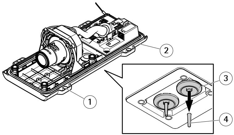
1 Bottom cover
2 Bottom cover screw T20 (4x)
3 Cable gasket M20 (2x)
4 Tab
- Push the network cable through the cable gasket.
NOTICE
If the network cable has a premounted network connector, remove the cable gasket and use the connector guard to prevent tearing of the cable gasket. Avoid using network cables with capped network connectors because they could cause tearing of the cable gasket despite using the connector guard.
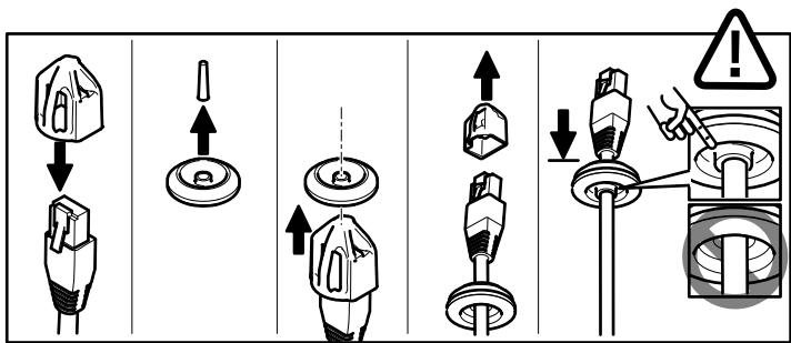
- Pull the network cable back slightly so that the cable gasket adjusts itself on the cable.
NOTICE
Not pulling the cable back could cause water to seep in and damage the product.
- Make sure that the cable gasket is fitted properly.
- If connecting an auxiliary device, for example an I/O, audio, or external power device, to the camera, repeat the steps above as applicable to the specific device.
NOTICE
Mount the connectors after the cables are pushed through the cable gasket.
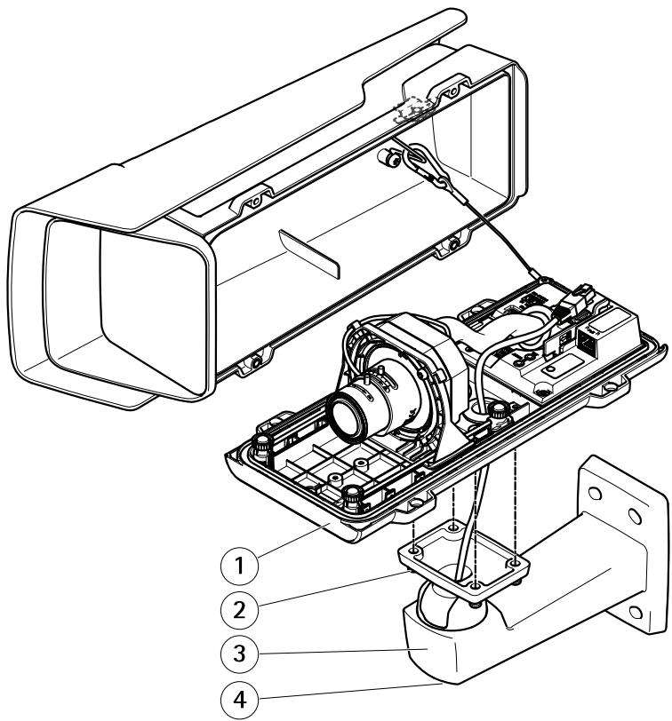
1 Bottom cover
2 Screw T20 (4x)
3 Wall bracket
4 Bracket adjustment screw T30
-
Put the bottom cover on the wall mount and tighten the screws (torque 2 Nm).
-
If applicable, connect external I/O devices or audio devices to the camera.
- If using an SD card for local storage, insert the card into the camera's SD card slot.
- Connect the network cable.
- Make sure that the camera LEDs indicate the correct condition. See LED Indicators on page 25.
- Loosen the bracket adjustment screw to aim the camera to the point of interest. For information about how to view the video stream, see How to access the product on page 20
- Set focus and zoom, see How to adjust focus and zoom on page 21
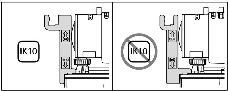
- On delivery, the lens is positioned correctly for IK10. If you move or replace the lens, you need to reposition the optical assembly to ensure IK10, see How to position the lens for IK10 on page 20.

1 Safety hook
2 Desiccant bag
- Remove the plastic wrapper from the desiccant bag.
- Remove the protective strip from the adhesive and attach the desiccant bag to the top cover.
- Close the housing. Alternately tighten the bottom cover screws a few turns at a time until they are tight (torque 1.5 Nm). This will compress the bottom cover gasket evenly.
NOTICE
Do not pinch any cables when closing the housing.
- If required, loosen the screws on the weather shield, adjust its position and tighten the screws.
How to set up corridor format
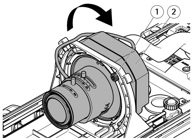
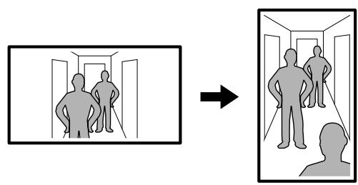
1 Lock screw (2x)
2 Optic unit
- Loosen the two lock screws.
- Rotate the optic unit.
- Tighten the lock screws.
- Go to the Stream tab on the product's webpage and rotate the view 90^ .
How to position the lens for IK10
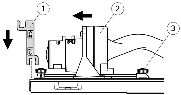
1 IK10 tool
2 Optic unit
3 Spring loaded thumb screw (4x)
- Zoom the lens to its widest position.
- Attach the IK10 tool to the bottom cover.
- Loosen the spring loaded thumb screws.
- Move the lens so that it touches the tool.
- Tighten the thumb screws.
How to access the product
AXIS IP Utility and AXIS Camera Management are recommended methods for finding Axis products on the network and assigning them IP addresses in Windows®. Both applications are free and can be downloaded from www-axis.com/support
The product can be used with the following browsers:
- Chrome™ (recommended), Firefox®, Edge®, or Opera® with Windows®
- Chrome™ (recommended) or Safari® with OS X®
- Chrome™ or Firefox® with other operating systems.
For more information about using the product, see the User Manual available at www-axis.com
How to adjust focus and zoom
If the camera is mounted so that you cannot look at the image and access the lens at the same time, use the Focus Assistant, see How to adjust focus with the Focus Assistant.
- Go to the Image tab in the product's webpage.
- Click Autofocus.
- Loosen the zoom and focus pullers on the lens by turning them counter-clockwise. See Product overview.
- Move the pullers to set zoom and focus and check the quality of the image in the image window.
- Re-tighten the zoom and focus pullers.
- Click Autofocus.
How to adjust focus with the Focus Assistant
Note
- The view in front of the camera should not be changed during focus adjustment. If the camera is moved, or if a finger or other object is placed in front of the lens, restart the procedure.
- If movements in front of the camera cannot be avoided, the Focus Assistant should not be used.
- If the control button is not released within two seconds, AXIS Internet Dynamic DNS Service is enabled instead of the Focus Assistant. For more information about AXIS Internet Dynamic DNS Service, see www-axis.com.
If the Status LED flashes either red or amber before you are able to adjust the lens, exit the Focus Assistant and restart the procedure. See Status LED behavior for focus assistant on page 25.
- Mount or place the camera so that it cannot be moved.
- Loosen the zoom puller by turning it anti-clockwise. Move the puller to set the zoom level. Retighten the zoom puller.
- Set the camera to its extreme distant-focus position by loosening the focus puller and turning the focus ring fully clockwise.
- Gently turn the focus ring anti-clockwise until it stops.
- Turn the focus ring slowly clockwise until the status indicator flashes green.
-
Re-tighten the focus puller.
-
Go to the Image tab in the product's webpage.
- Click Autofocus and follow the instructions from the wizard.
How to reset to factory default settings
Important
Reset to factory default should be used with caution. A reset to factory default resets all settings, including the IP address, to the factory default values.
To reset the product to the factory default settings:
- Disconnect power from the product.
- Press and hold the control button while reconnecting power. See Product overview.
- Keep the control button pressed for 15-30 seconds until the status LED indicator flashes amber.
- Release the control button. The process is complete when the status LED indicator turns green. The product has been reset to the factory default settings. If no DHCP server is available on the network, the default IP address is 192.168.0.90
- Use the installation and management software tools to assign an IP address, set the password, and access the video stream.
The installation and management software tools are available from the support pages on www-axis.com/support
- Refocus the product.
Further information
For the latest version of this document, see www-axis.com
- The user manual is available at www-axis.com
- To check if there is updated firmware available for your product, see www-axis.com/support
- For useful online trainings and webinars, see www-axis.com/academy
Optional accessories
For a complete list of available accessories for this product, go to www-axis.com
Technical specifications
To find the latest version of the datasheet, go to www-axis.com > product > Support &t Documentation.
LED Indicators
| Status LED | Indication |
| Green | Steady green for normal operation. |
| Amber | Steady during startup. Flashes when restoring settings. |
| Network LED | Indication |
| Green | Steady for connection to a 100 Mbit/s network. Flashes for network activity. |
| Amber | Steady for connection to a 10 Mbit/s network. Flashes for network activity. |
| Unlit | No network connection. |
| Power LED | Indication |
| Green | Normal operation. |
| Amber | Flashes green/amber during firmware upgrade. |
Status LED behavior for focus assistant
The status LED flashes when the Focus Assistant is active.
| Color | Indication |
| Red | The image is out of focus. Adjust the lens. |
| Amber | The image is close to focus. The lens needs fine tuning. |
| Green | The image is in focus. |
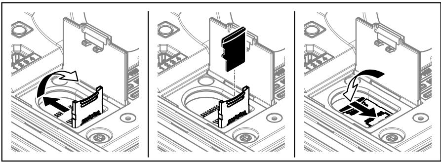
SD card slot
NOTICE
- Risk of damage to SD card. Do not use sharp tools, metal objects, or excessive force when inserting or removing the SD card. Use your fingers to insert and remove the card.
- Risk of data loss and corrupted recordings. Do not remove the SD card while the product is running. Disconnect power or unmount the SD card from the product's webpage before removal.
This product supports microSD/microSDHC/microSDXC cards (not included).
For SD card recommendations, see www-axis.com
Buttons
Control button
The control button is used for:
- Enabling the Focus Assistant. Press and very quickly release the Control button.
- Resetting the product to factory default settings. See How to reset to factory default settings on page 23.
- Connecting to an AXIS Video Hosting System service or AXIS Internet Dynamic DNS Service. For more information about these services, see the User Manual.
Connectors
Network connector
RJ45 Ethernet connector with Power over Ethernet (PoE).
NOTICE
Due to local regulations or the environmental and electrical conditions in which the product is to be used, a shielded network cable (STP) may be appropriate or required. All cables connecting the product to the network and that are routed outdoors or in demanding electrical environments shall be intended for their specific use. Make sure that the network devices are installed in accordance with the manufacturer's instructions. For information about regulatory requirements, see Electromagnetic compatibility (EMC) 4.
Audio connector
The Axis product has the following audio connectors:
Audio in - 3.5 mm input for a mono microphone, or a line-in mono signal (left channel is used from a stereo signal).
- Audio out - 3.5 mm output for audio (line level) that can be connected to a public address (PA) system or an active speaker with a built-in amplifier. A stereo connector must be used for audio out.
3.5 mm audio connectors (stereo)
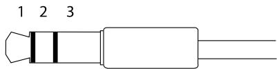
| 1 Tip | 2 Ring | 3 Sleeve | |
| Audio Input | Microphone/Line in | Ground | |
| Audio Output | Line out (mono) | Ground | |
About I/O connectors
Use the I/O connector with external devices in combination with, for example, tampering alarms, motion detection, event triggering, and alarm notifications. In addition to the 0 V DC reference point and power (DC output), the I/O connector provides the interface to:
Digital output - For connecting external devices such as relays and LEDs. Connected devices can be activated by the VAPIX® Application Programming Interface or in the product's webpage.
Digital input - For connecting devices that can toggle between an open and closed circuit, for example PIR sensors, door/window contacts, and glass break detectors.
4-pin terminal block
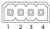
| Function | Pin | Notes | Specifications |
| 0 V DC (-) | 1 | DC ground | 0 V DC |
| DC output | 2 | Can be used to power auxiliary equipment. Note: This pin can only be used as power out. | 12 V DC Max load = 50 mA |
| Configurable (Input or Output) | 3-4 | Digital input – Connect to pin 1 to activate, or leave floating (unconnected) to deactivate. | 0 to max 30 V DC |
| Digital output – Connected to pin 1 when activated, floating (unconnected) when deactivated. If used with an inductive load, e.g., a relay, a diode must be connected in parallel with the load, for protection against voltage transients. | 0 to max 30 V DC, open drain, 100 mA |
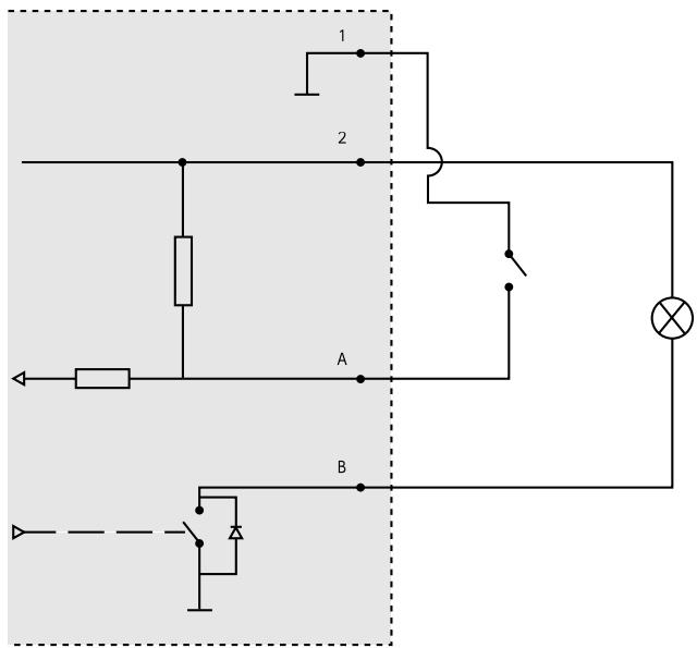
1 O V D C(-)
2 DC output 12 V, max 50 mA
A I/O configured as input
B I/O configured as output
RS485/RS422 connector
Two 2-pin terminal blocks for RS485/RS422 serial interface used to control auxiliary equipment such as pan-tilt devices.
The serial port can be configured to support:
- Two-wire RS485 half duplex
- Four-wire RS485 full duplex
- Two-wire RS422 simplex
- Four-wire RS422 full duplex point to point communication
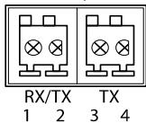
RS485/422
| Function | Pin | Notes |
| RS485B alt RS485/422 RX(B) | 1 | RX pair for all modes (combined RX/TX for 2-wire RS485) |
| RS485A alt RS485/422 RX(A) | 2 | |
| RS485/RS422 TX(B) | 3 | TX pair for RS422 and 4-wire RS485 |
| RS485/RS422 TX(A) | 4 |
Important
The recommended maximum cable length is 30m (98 ft).
Operating conditions
| Product | Temperature | Humidity |
| AXIS P1367-E | -40 °C to 55 °C (-40 °F to 131 °F) Maximum temperature (intermittent): 60 °C (140 °F) | 10–100% RH (condensing) |
Power consumption
NOTICE
Use a limited power source (LPS) with either a rated output power limited to ≤ 100W or a rated output current limited to ≤ 5A .
| Product | Power over Ethernet (PoE)IEEE 802.3af/802.3at Type 1 Class 3 |
| AXIS P1367-E | Max. 9.2 WTypical 5.3 W |
Safety information
Hazard levels
DANGER
Indicates a hazardous situation which, if not avoided, will result in death or serious injury.
WARNING
Indicates a hazardous situation which, if not avoided, could result in death or serious injury.
CAUTION
Indicates a hazardous situation which, if not avoided, could result in minor or moderate injury.
NOTICE
Indicates a situation which, if not avoided, could result in damage to property.
Other message levels
Important
Indicates significant information which is essential for the product to function correctly.
Note
Indicates useful information which helps in getting the most out of the product.
Safety instructions
NOTICE
- The Axis product shall be used in compliance with local laws and regulations.
- Store the Axis product in a dry and ventilated environment.
- Avoid exposing the Axis product to shocks or heavy pressure.
- Do not install the product on unstable poles, brackets, surfaces or walls.
- Use only applicable tools when installing the Axis product. Using excessive force with power tools could cause damage to the product.
- Do not use chemicals, caustic agents, or aerosol cleaners.
- Use a clean cloth dampened with pure water for cleaning.
- Use only accessories that comply with the technical specification of your product. These can be provided by Axis or a third party. Axis recommends using Axis power source equipment compatible with your product.
- Use only spare parts provided by or recommended by Axis.
- Do not attempt to repair the product yourself. Contact Axis support or your Axis reseller for service matters.
Transportation
NOTICE
- When transporting the Axis product, use the original packaging or equivalent to prevent damage to the product.
Battery
The Axis product uses a 3.0 V CR2032 lithium battery as the power supply for its internal real-time clock (RTC). Under normal conditions this battery will last for a minimum of five years.
Low battery power affects the operation of the RTC, causing it to reset at every power-up. When the battery needs replacing, a log message will appear in the product's server report. For more information about the server report, see the product's setup pages or contact Axis support.
The battery should not be replaced unless required, but if the battery does need replacing, contact Axis support at www-axis.com/support for assistance.
Lithium coin cell 3.0V batteries contain 1,2-dimethoxyethane; ethylene glycol dimethyl ether (EGDME), CAS no. 110-71-4.
WARNING
- Risk of explosion if the battery is incorrectly replaced.
-
Replace only with an identical battery or a battery which is recommended by Axis.
-
Dispose of used batteries according to local regulations or the battery manufacturer's instructions.
EN
Axis Communications AB, 2017
Ver. M1.3
Date: May 2017
Part No. 1741438