
ECLIPSE - Air-conditioner FABER - Free user manual and instructions
Find the device manual for free ECLIPSE FABER in PDF.
| Product type | Extractor hood (called a climate conditioner but functions as a hood) |
| Brand | FABER |
| Model | ECLIPSE |
| Category | Extractor hood |
| Minimum safety distance | 650 mm between cooking surface and hood (may vary by model) |
| Exhaust duct diameter | 120 mm or 150 mm (reducible with supplied nozzle) |
| Installation version | Extracting (external exhaust) or recirculating (recycling with charcoal filter) |
| Ventilation speeds | 3 speeds + boost (4th speed timed 6 minutes) |
| Lighting | Integrated, LED or halogen bulbs (precision not given) |
| Grease filters | Self-supporting metal filters, dishwasher safe (about every 2 months) |
| Activated charcoal filter | Not washable, replace every 4 months (or more often depending on use) |
| Power supply | Mains voltage (not specified, typical 220-240 V) – requires double-pole switch |
| Electrical class | Class I (requires grounding) |
| Power cable length | Not specified |
| Weight | Not specified (estimated ~10-15 kg) |
| Dimensions (W x D x H) | Not specified, depends on installation configuration |
| Control type | Buttons with indicator lights for speeds and light |
| Air exhaust | Upper or rear outlet possible, with reduction cap |
| Material | Not specified (stainless steel probable) |
| Noise level | Not specified |
| Installation | Wall mounting, requires at least two persons for installation |
| Child safety | Do not let children play with the appliance |
| Maintenance | Regular cleaning of filters and hood, do not use flame under hood |
| Spare parts / repairability | Contact after-sales service for replacement of lighting and other parts |
| Warranty | Not specified |
Frequently Asked Questions - ECLIPSE FABER
User questions about ECLIPSE FABER
0 question about this device. Answer the ones you know or ask your own.
Ask a new question about this device
Download the instructions for your Air-conditioner in PDF format for free! Find your manual ECLIPSE - FABER and take your electronic device back in hand. On this page are published all the documents necessary for the use of your device. ECLIPSE by FABER.
USER MANUAL ECLIPSE FABER
For your safety and correct operation of the appliance, read this manual carefully before installation and use. Always keep these instructions with the appliance even if you move or sell it. Users must fully know the operation and safety features of the appliance.

The wire connection has to be done by specialized technician.
- The manufacturer will not be held liable for any damages resulting from incorrect or improper installation.
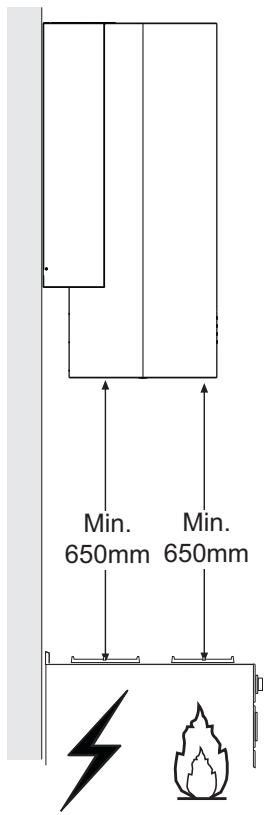
- The minimum safety distance between the cooker top and the extractor hood is 650~mm (some models can be installed at a lower height, please refer to the paragraphs on working dimensions and installation).
- If the instructions for installation for the gas hob specify a greater distance, this must be respected.
- Check that the mains voltage corresponds to that indicated on the rating plate fixed to the inside of the hood.
- Means for disconnection must be incorporated in the fixed wiring in accordance with the wiring rules.
- For Class I appliances, check that the domestic power supply guarantees adequate earthing.
- Connect the extractor to the exhaust flue through a pipe of minimum diameter 120 ~mm . The route of the flue must be as short as possible.
- Regulations concerning the discharge of air have to be fulfilled.
-
Do not connect the extractor hood to exhaust ducts carrying combustion fumes (boilers, fireplaces, etc.).
-
If the extractor is used in conjunction with non-electrical appliances (e.g. gas burning appliances), a sufficient degree of aeration must be guaranteed in the room in order to prevent the backflow of exhaust gas. When the cooker hood is used in conjunction with appliances supplied with energy other than electric, the negative pressure in the room must not exceed 0,04 mbar to prevent fumes being drawn back into the room by the cooker hood.
- The air must not be discharged into a flue that is used for exhausting fumes from appliances burning gas or other fuels.
- If the supply cord is damaged, it must be replaced from the manufacturer or its service agent.
- Connect the plug to a socket complying with current regulations, located in an accessible place.
- With regards to the technical and safety measures to be adopted for fume discharging it is important to closely follow the regulations provided by the local authorities.
WARNING: Before installing the Hood, remove the protective films. - Use only screws and small parts in support of the hood.
WARNING: Failure to install the screws or fixing device in accordance with these instructions may result in electrical hazards. - Do not look directly at the light through optical devices (binoculars, magnifying glasses...).
- Do not flambé under the range hood; risk of fire.
- This appliance can be used by children aged from 8 years and above and persons with reduced physical, sensory or mental capabilities or lack of experience and knowledge if they have been given supervision or instruction concerning use of the appliance in a safe way and understand the hazards involved. Children shall not play with the appliance. Cleaning and user maintenance shall not be made by children without supervision.
-
Children should be supervised to ensure that they do not play with the appliance.
-
The appliance is not to be used by persons (including children) with reduced physical, sensory or mental capabilities, or lack of experience and knowledge, unless they have been given supervision or instruction.
Accessible parts may become hot when used with cooking appliances. - Clean and/or replace the Filters after the specified time period (Fire hazard). See paragraph Care and Cleaning.
- There shall be adequate ventilation of the room when the range hood is used at the same time as appliances burning gas or other fuels (not applicable to appliances that only discharge the air back into the room).
- The symbol on the product or on its packaging indicates that this product may not be treated as household waste. Instead it shall be handed over to the applicable collection point for the recycling of electrical and electronic equipment. By ensuring this product is disposed of correctly, you will help prevent potential negative consequences for the environment and human health, which could otherwise be caused by inappropriate waste handling of this product. For more detailed information about recycling of this product, please contact your local city office, your household waste disposal service or the shop where you purchased the product.
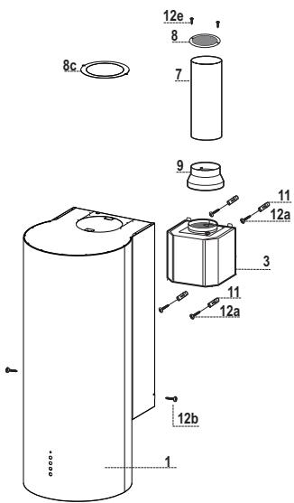
Components
| Ref. | Q.ty | Product Components |
| 1 | 1 | Hood Canopy complete with: Controls, Light, Filters |
| 3 | 1 | Suction unit |
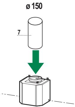
| 7 | 1 | PVC Pipe |
| 8 | 1 | Directional Grille |
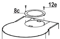
| 8c | 1 | Air outlet reducerplug |
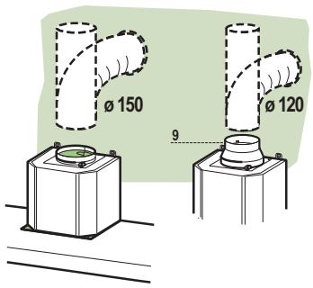
| 9 | 1 | Reduction flangeø 150-120 mm |
| Ref. | Q.ty | Installation Components |
| 11 | 4 | Wall plugsø 10 |
| 12a | 4 | Screws 4.2 x 44.4 |
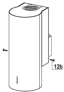
| 12b | 2 | Screws M3 x 8 Torx |
| 12e | 6 | Screws 2.9 x 9.5 |
| Q.ty | Documentation | |
| 1 | Instruction Manual |
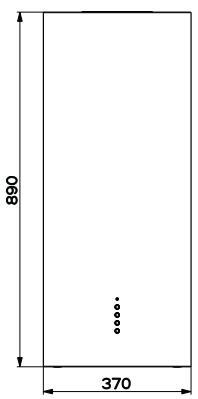
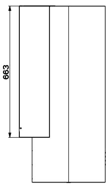
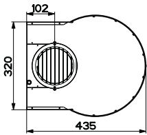
Dimensions
Given the complexity of installation operations, they should be carried out by at least two people.
If the hood is fitted in the recirculation version, bear in mind that there must be a minimum distance of at least 8-10 Cm left between the top of the hood and the surface above it (ceiling or shelf).
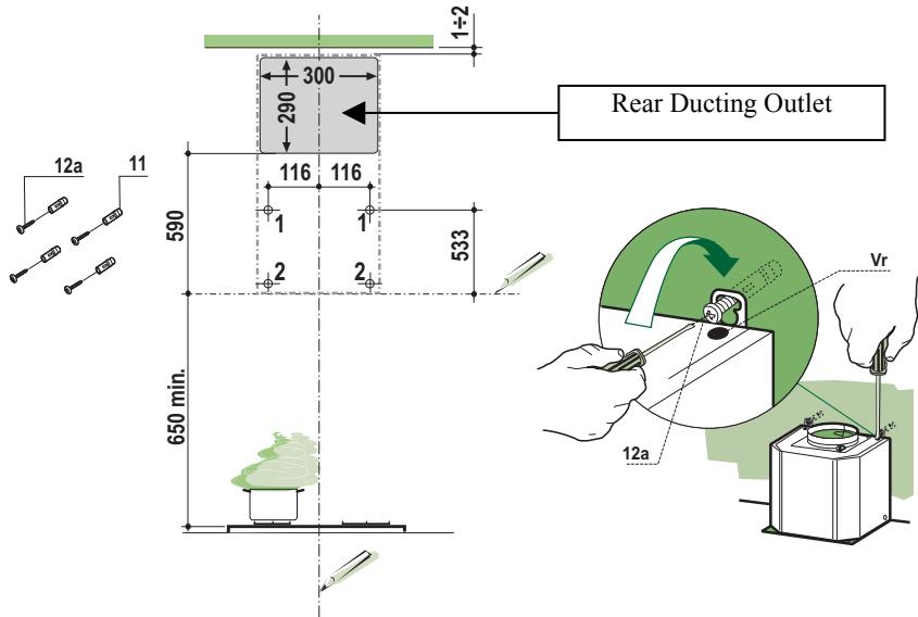
Draw the following on the Wall:
- a Vertical line up to the ceiling or top surface, at the centre of the area in which the Hood is to be fitted;
- a Horizontal line: 650 ~mm min. above the Cooker Top.
- As shown in the drawing, mark a reference point (1) 116mm from the vertical reference line, and 533mm above the horizontal reference line.
- Repeat this operation on the other side, checking to ensure it is level.
- Drill the points marked using a 8mm drill bit.
- Insert the plugs 11 into the holes.
- Tighten the 2 screws 12a (4.2 x 44.4) provided in the bores, leaving a gap of 5 - 6mm between the wall and the heads of the screws.
- Lock the 2 screws Vr located on the connection points for the Motor unit 3.
- Hook the Motor unit 3 to the screws 12a.
- Turn screws Vr to level the hood canopy.
- Mark the reference points (2) for the brackets hooked under the Motor unit 3, as shown.
- Drill the points marked using a 0.8mm drill bit.
- Insert the plugs 11 into the holes.
- Insert 2 of the screws 12a (4.2 x 44.4) provided into the bores.
- Tighten the 4 screws 12a fixing the Suction Unit completely.
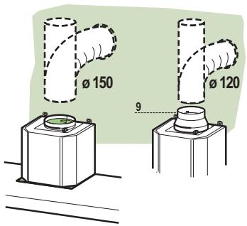
When installing the Ducting version, join the Hood to the outlet duct using a rigid or flexible pipe 150 or 120~mm , selection of which is at the discretion of the installation technician. The pipe may come out of the hood either at the top or at the back.
REAR OUTLET
- Remember that when drilling the ducting opening you must follow the diagram provided in the paragraph on drilling the wall.
- To connect using a 0120 ~mm pipe, insert the reduction Flange 9 onto the Hood canopy outlet.
- Fasten the pipe using suitable pipe clamps. The materials required to do so are not provided.
- Remove any Activated charcoal filters.
TOP OUTLET
- To connect using a 0.150 ~mm pipe, connect the Hood to the outlet duct using a rigid or flexible pipe.
- To connect using a 120 mm pipe,insert the reduction Flange 9 onto the Hood canopy outlet.
- Connect the Hood to the outlet duct using a rigid or flexible pipe.
- Fasten the pipe using suitable pipe clamps. The materials required to do so are not provided.
- Remove any Activated charcoal filters.
AIR OUTLET - RECIRCULATION VERSION
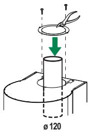
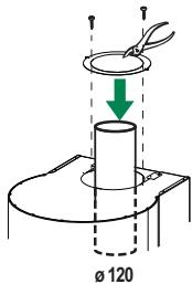
- Insert the PVC pipe 7 provided onto the Hood canopy outlet.
- Push the pipe all the way in.

Ducting Version Rear outlet
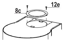
- If the air outlet on the Rear of the hood has been selected, the Air outlet Reductionplug 8c must be screwed into the top part of the Hood using 2 Screws 12e provided.
Ducting Version Top outlet
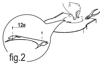
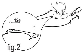
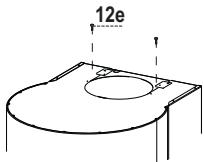
- If the air outlet on the top of the hood has been selected, the 2 brackets visible in the top part of the hood canopy must be removed. Also remove the pre-scored section shown in (Fig. 2) to allow the pipe to pass through.
- Screw the brackets to the pre-scored piece, after removing it as described above, using 2 screws 12e provided.
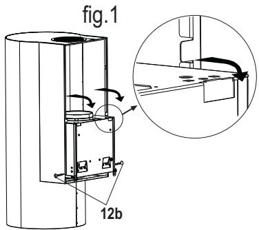
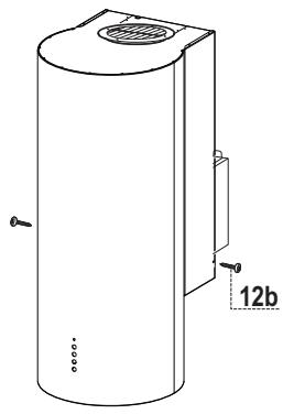
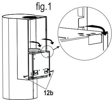
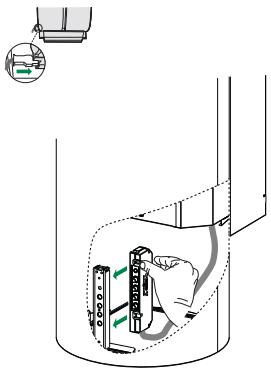
- Rest the Hood Canopy 1 on the Suction Unit 3, inserting it, and fix it at the side using the 2 screws 12b. (Fig.1)
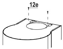
- Screw the pre-scored piece with the brackets (Fig.2) back onto the top part of the hood canopy, using 2 screws 12e provided, so as to block the air ducting pipe.
- If a size 120 pipe is used, break the inner part of the air outlet Reductionplug 8c. Insert the ring obtained in this way into the air ducting pipe and screw it to the hood canopy using 2 screws 12e provided.
Fitting the hood body - Recirculation Version
- Detach the 2 brackets that can be seen inside the opening on the top part of the hood canopy.
- Rest the Hood Canopy 1 on the Suction Unit 3, inserting it, and fix it at the side using the 2 screws 12b.
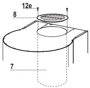
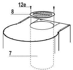
- Position the directional grille 8 on the pipe and check that it has been fitted properly.
- Fasten the directional grille 8 using the screws 12e provided.
- Make sure that the Activated charcoal odour filter has been fitted.
Electrical connection
- Connect the Hood to the Mains Power Supply, inserting a bipolar switch with a contact aperture of at least 3mm .
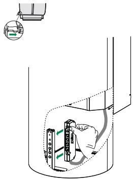
- Remove the filter and make sure that the Power cable has been properly inserted into the Suction fan socket
- Take the control box inside the suction unit 3 and slot it into the plastic support provided for it in the hood canopy at the height of the controls.
- Pass an fix the wiring through with the Adhesive cable tie already monted.
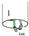
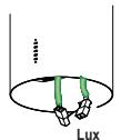
- Fasten the Spotlights connector Lux.
- For the Recirculation Version, fit the Activated Charcoal Odour Filter.
- Replace the metal grease filters.

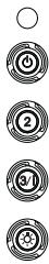
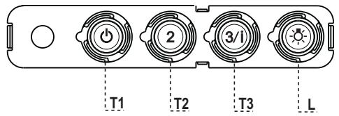
Control panel
| BUTTON | LED | FUNCTIONS |
| T1 Speed | On | Turns the Motor on at Speed one. |
| Turns the Motor off. | ||
| T2 Speed | On | Turns the Motor on at Speed two. |
| T3 Speed | Fixed | When pressed briefly, turns the Motor on at Speed three. |
| Flashing | Pressed for 2 Seconds. | |
| Activates Speed four with a timer set to 6 minutes, after which it returns to the speed that was set previously. Suitable to deal with maximum levels of cooking fumes. | ||
| L Light | Turns the Lighting System on and off. |
Warning: Button T1 turns the motor off, after first passing to speed one.
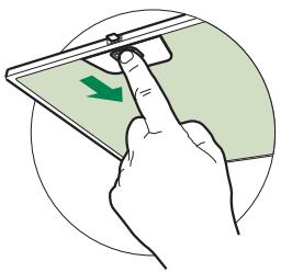
Grease filters
CLEANING METAL SELF- SUPPORTING GREASE FILTERS
- The filters must be cleaned every 2 months of operation, or more frequently for particularly heavy usage, and can be washed in a dishwasher.
- Remove the filters one at a time by pushing them towards the back of the group and pulling down at the same time.
- Wash the filters, taking care not to bend them. Allow them to dry before refitting.
- When refitting the filters, make sure that the handle is visible on the outside.
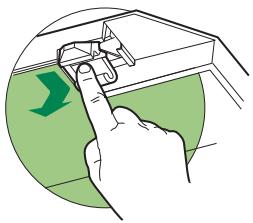
Activated charcoal filter (Recirculation version)
REPLACING THE ACTIVATED CHARCOAL FILTER
- The filter is not washable and cannot be regenerated, and must be replaced approximately every 4 months of operation, or more frequently for particularly heavy usage.
- Remove the metal grease filters.
- Remove the saturated activated carbon filter by releasing the fixing hooks.
- Fit the new filter by hooking it into its seating.
- Refit the metal grease filters.
Lighting unit
- For replacement contact technical support ("To purchase contact technical support").
(1)
CoeHHeHne BbInycka BO3dyxa BCacbIbAioJeBbl
TAXKIN
Дя устайбкн BCaCbIBAHOJIe BByTЯKKN COeIHINHTe ee c BbIyucKHO Tpy6oJ KectKoH HJIn Tn6KoT py6ko J 150 HJIn 120 MM IIO ycMOTpeHHIO MOHTaKHIIKA. Tpy6ka MoKeT BbIXOINTB KaK CBepxY, TaK i C3aINBbITaKKN.
BbIIYCK BO3JUVXA C3AIN
_TO6bI cJIeIaTb OTBepCTHe IINr OTBeJeHnB O3Jyxa, cJIeIyET IIpHIEpKHNBaTbcra Cxembl, IIpHBeJeHHo B pa3JIe "OTBepCTnB BCtHe".
Длг coeHHeHnCtpy6KoI 120MMBCTaBBteIpePExOJIbHbI ΦlaHe9BbYIIpyCKHOETBepCTHe B KOpIpyCE BbITJIKN.
3aKpeHHTe Tpy6ky CIEUHaJIbHbIMN Tpy6HbIMN 3aJHMAMH. Heo6xoIIMbI MaTePnJI He BxOJNTB KOMIIJEKT NIOCTABKN.
- BbHbTe ΦHbTpbl IipOTNb 3aIIaXOB Ha aKTHBnPOBaHHOM yTJIe.
BbIyCK BO3DyXA CBEPXV
Длгсоeннньгяжнтубког0150MMcoeHHHTeecBbIyckhoTpyoohJcctKoHJIINrOkoTpy6koi.
Длг coeHHeHnCtpy6KoI 0120MMBCTaBBteIpepExOJIbHbI _IIAHeI9 BBbYcHKoeOTBepCTHe B KOpIyce BbITKaKN.
- CoeHHHTe BbTgKky c BbIyckHoi Tpy6oJ JeecTKoJ HIn H6KOJI Tpy6koJ.
3aKpeHHTe Tpy6ky CIEUHAJIbHbIMN Tpy6HbIMN 3aJHMAMH. Heo6XoDMbI MaTeHnJI HE BxoIHTB KOMJIJEKT NIOCTABKN.
BbHbTe hIbTpbl IpOTnIB 3aIaxOB Ha aKTHBnPoBaHHom yTJe.
BbIpyCK BO3dYXA N3 ΦNJIbTPYIOUeBbITJXKKI
BcTaBbTe IpiHJIarAeMyIO B KOMIIJIeKTe Tpy6Ky H3 IIBX 7 B BbIyckHOE OTBepCTHe KOpIIyCa BbITaKKN.
- HαχmHTe Na trpy6ky Do yIopa.
Bcacsbaioa BbITKKa C 3aHMM BbIyckom Bo3dyxa
- EcIN Bb6paH BapHaHT c 3aIHHM BbIyckOM Bo3Jyxa H3 BbITJIKK, CJeJyET IIpHBHTHTb 3aJIYIIky - IepexOHNbI JIaHeI BbIycka BO3Jyxa 8c 2 IIpHJaRaembIMn BHTamn 12e B BepxHei Yactn BbITJIKK.
BcacsbIbaIOaBbITKa c BepxHMM BblNyCKOM BO3dYxa
- EcJIN BbIbpaH BapHaHT c BbIyucKOM Bo3dYxa H3 BepXHei YacTH N BbITJxKKn, CJeJeYET OTJeJIHTb 2 CKO6bl, BNHbIE BHyTpN OTBepCTHn B cepXHei Yactn KOpIyCa BbITJxKKn. CHMNTe TaKKe 3JIeMeHT c HaIpe3KoN (PcC. 2), YTO6bl IIPOJIOJKTb Tpy6Ky.
- IIpHbHTIe cKO6bI K CHTOMy 3JIeMeHTy cHa,Ipe3KoI 2 IIpHJIaRaembIMn BHTamH 12e.
-ПинлжКпЕ и НаДeнБтЕ корпс CBытяЖКИ 1 Ha BытяЖСоан aANIIapat 3,ЗakpeПNTe erO ПО 6OKam 2 BnHTAMH 12b. (Pnc.1)
- IIpHbHHTHTe 3JIeMeHT c HaIpe3KoB BMeCTe COCKo6aMH (Pc. 2) K BepxHei YAcTH N BbITJgKHN 2IIpHJIaIaEMyBMH B KOMIIJIeKTe BHHTaMH 12e, YTO6bI 3aΦHKCHPOBaTb Tpy6ky OTBeJeHHN BO3JyXa B IIOJIOKeHHN.
- IIpn HcIOJIb3OBAHnN Tpy6Kn 120 Ipo6eIte BHyTppeHHIOU qactb 3aJIyIiKN - IepexoIHOro JlaHua BbIXOJa BO3Dyxa 8c. YcTaHOBHTe IOJyuYeHHoe TaKHM O6pa3OM KOJIbIO Ha Tpy6ky IJIa OTBeJeHnBa BO3Dyxa I IpiHBnHTHe ee IpiHJaRaEmbIM N KOMIIJEKeTc 2 BnHTamn 12e.
UcTaHOBka Kopnyca funbtpyooe BblTJKKN
- OTДeЛНТе 2 сКоБы, ВДИнБIE BHyTpH OТВерстЯВ ВьрхЕнЧастн КОПИУСа ВьтЯЖKN.
-Пинлжнe И Надeнte KОрпсь BытякN 1Ha BытякHоаПарТ3,ЗakpeПNTe erO ПО 6OKam 2 BHTAMn 12b. - YcTaHOBnTe peRyIINpyEmyIO peIeTky 8 Ha Tpy6y I pIOBepbTe IIpaBnJIbHocTb ee yCTaHOBKn.
- IIpHbHTHTe peRyJHPyEmyIO peIITKy 8 IIpJIaRaEMbIMN BHTAMH 12e.
- IIpoBepbTe HaJIHcne HJIbTpOB IIpoTb 3aIaxOB HaakTHBnPoBAHHOM yTJIe.
3neKtpueckoe nodknOuHne
CoeHHHTe BbITKky C cetbIO IINTaHnuepe3IByXIIIOIOCHbI BbIKJIOHaTeJIb C MHHMaJIbHbIM pa3BeJeHHem KOHTaKTOB 3 MM.
BbHbTe fHJIbTp H IIPOBepbTe, YTO6bI coeINHHTeJIbHbI 3aJHM IHTaHOIIero Ka6eJIg 6bl IpaBnJIbHO BCTaBJeH B pa3bem BbITJHKHOYcTpoiCTBa.
- Bo3bMHTe Kopo6ky yIpaBJIeHn BHyTpH bByTJxHO r anIIapata 3 H BCTaBBte ee B CIIeHaJIbHbI IJIaCTHKOBbI IepKaTeJIb B KOpIIyCe BbITJxKKn Ha ypOBHe yCTpoHCTB yIpaBJIeHn.
- 3aKpeIInTe IpoBOJa BHyTpN KOpIIyCa c IpiOKJIaIKoJ JeHTbI yKe yCTaHOBJIeHbI.
CoeHHHTe 3aJHM JAmIOueK OcBeHHeHn Lux.
B HJIbTpmyIe BbITgKke yCTaHOBHTe HJIbTp IIPOTHB 3aIIAXOB Ha aKTHBnPOBaHHOM yTJIe.
- IIOCTaBbTe Ha MeCTo JHPOBbIe _HJIbTpbl

HaeJeIb ynpabJIeHHa
- Components
- Dimensions
- REAR OUTLET
- TOP OUTLET
- AIR OUTLET - RECIRCULATION VERSION
- Ducting Version Rear outlet
- Ducting Version Top outlet
- Fitting the hood body - Recirculation Version
- Electrical connection
- Grease filters
- CLEANING METAL SELF- SUPPORTING GREASE FILTERS
- Activated charcoal filter (Recirculation version)
- REPLACING THE ACTIVATED CHARCOAL FILTER
- Lighting unit
- CoeHHeHne BbInycka BO3dyxa BCacbIbAioJeBbl
- TAXKIN
- BbIIYCK BO3JUVXA C3AIN
- BbIyCK BO3DyXA CBEPXV
- BbIpyCK BO3dYXA N3 ΦNJIbTPYIOUeBbITJXKKI
- Bcacsbaioa BbITKKa C 3aHMM BbIyckom Bo3dyxa
- BcacsbIbaIOaBbITKa c BepxHMM BblNyCKOM BO3dYxa
- UcTaHOBka Kopnyca funbtpyooe BblTJKKN
- 3neKtpueckoe nodknOuHne
Brand : FABER
Model : ECLIPSE
Category : Air-conditioner