DAKAR PLUS - Industrial water pump SIMA - Free user manual and instructions
Find the device manual for free DAKAR PLUS SIMA in PDF.


User questions about DAKAR PLUS SIMA
0 question about this device. Answer the ones you know or ask your own.
Ask a new question about this device
Download the instructions for your Industrial water pump in PDF format for free! Find your manual DAKAR PLUS - SIMA and take your electronic device back in hand. On this page are published all the documents necessary for the use of your device. DAKAR PLUS by SIMA.
USER MANUAL DAKAR PLUS SIMA
"EC" DECLARATION OF CONFORMITY
SIMA, S.A.
Poligono Industrial Juncaril, C/ Albuñol, Parcela 250 C. P. 18220 Albolote, Granada (SPAIN)
Company responsible for manufacturing and commercialising the below specified machine:
MATERIALS TABLE SAW
DECLARES:
That the above mentioned machine designed for masonry cutting of stone and other
construction materials is in conformity with all applicable provisions of the Directive of Machines (2006/42/CE) and the national applicable regulations.
The machine is also in conformity with EC applicable provisions:
2006/95/CE; 2004/108/CE; 2000/14/CE; 2002/44/CE; 2002/95/CE; 2002/96/CE
The machine is also in conformity with the provisions of the following applicable norms
Details of the authorized person to elaborate the technical file
Eugenio Fernández Martín
Technical Department Manager
SIMA S.A.
Poligono Industrial Juncaril, C/ Albuñol, Parcela 250 - 18220 Albolote, Granada (SPAIN)
Albolote 01.01.2010

sima
Signed:
Javier Garcia Marina
Managing Director
INDEX
"EC" DECLARATION OF CONFORMITY 3
-
GENERAL INFORMATION 5
-
GENERAL DESCRIPTION OF THE MACHINE 5
2.1 PICTOGRAMS 6
2.2 TRANSPORT 6
- ASSEMBLING INSTRUCTIONS 6
3.1 TO SET THE MACHINE 6
3.2 FILLING THE WATER TRAY 7
-
ELECTRICAL PLUGGING AND ADJUSTING THE DISK ROTATION SENSE..... 7
-
MOUNTING AND DISmountING THE CUTTING DISK 7
5.1 MOUNTING/ REPLACING THE CUTTING DISK 7
- ELECTRICAL EQUIPMENT 8
6.1 SINGLE-PHASE MACHINES 8
6.2 THREE PHASES ELECTRIC MOTORS 8
-
SEGURITY RECOMENDATIONS 9
-
MACHINE STARTING-UP AND USING INSTRUCTIONS 9
8.1 POSITION OF THE MACHINE AND THE OPERATOR, CONNECTION AND DISCONNECTION 9
8.2 ADJUSTING THE HEIGHT OF THE CUTTING HEAD 9
8.3 REALISING A STRAIGHT CUT 10
8.4 REALISING A 45^ CUT 10
8.5 REALISING A DIAGONAL CUT 10
8.6 CUTTING IN DOWNWARD MOTION 10
8.7 SAFETY RECOMMENDATIONS 10
- MAINTENANCE 11
9.1 SUBSTITUTING A DETERIORATED DISK 11
9.2 ALIGNING THE DISK 12
9.3 ALIGNMENT GUIDES 12
- SOLUTIONS TO MOST FREQUENT ANOMALIES 13
- TECHNICAL CHARACTERISTICS 14
- WARRANTY 15
- SPARE PARTS 15
- ENVIRONMENT PROTECTION 15
- DECLARATIONS ON NOISES 15
- DECLARATIONS ON MECHANICAL VIBRATIONS 15
- ELECTRICAL SCHEMES 16
WARRANTY CERTIFICATE 22
1. GENERAL INFORMATION
WARNING: Pease read and understand perfectly the present instruction before using the machine.
SIMA S.A. thanks you for your trust in our products and for purchasing the TABLE SAW DAKAR PLUS model
This manual provides you with the necessary instructions to start, use, maintain and in your case, repair of the present machine. All aspects as far as the safety and health of the users is concerned have been stated. Respecting all instructions and recommendations assures safety and low maintenance. As such, reading this manual carefully is compulsory for any person responsible for the use, maintenance or repair of this machine.
As such, reading this manual carefully is compulsory for any person responsible for the use, maintenance or repair of this machine.
It is recommended to have always this manual in an easily accessible place where the machine is being used.
2. GENERAL DESCRIPTION OF THE MACHINE
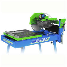
SIMA Cutting Table Saws, DAKAR PLUS models, are designed and manufactured to be used at masonry building sites, in particular to cut until 20 cm high concrete blocks and other construction materials, mineral and compounds with at least one bearing side (tile, terrazzo, brick, marble, granite, concrete or ceramics shingle, stoneware... The cutting tool is a diamond disk powered by an electric motor and water cooled by a closed-circuit pump. The progress of the disk is done manually by moving the cutting head in the direction of the material to be cut. The DAKAR PLUS models are manufactured of high quality materials.
Any use other than the machine has been designed for is considered inappropriate and can be dangerous; therefore, it is expressly prohibited.
DAKAR PLUS models are very reliable table saw on work sir, capable to performance mitring and 90^ cutting.
- Enable to move the head up and down directions easily and manually way, through turning and blocking the head using the handle proportionate for the purpose
The head of the motor keep the right balance even when the block is cancel due a spring.
- Its steel chassis avoid vibrations during cutting. Therefore we get a better efficiency of the diamond blade.
- The sliding cart is supported by four wheels which roll over two rolling tracks build with a "U" frame. A rubber protection is dispose on the sliding cart in its upper side to avoid the sliding of the material being cut.
The machine has four demountable legs to facilitate its transport and handles for its displacement.
It has been furnished with a graduated ruler to cut pieces in angles. It carries out mitre-cuts up to 45^
- The machine is protected with an anti-splatter screen to avoid the water splashing towards the back part of the machine where the cutting is being performed.
The frame of the machine is painted with a highly resistant anti-corrosion epoxy polyester paint.
This machine has been designed and manufactured to cut with a water cooled diamond disk. The cooling is carried out by a closed-circuit electric pump with a constant water flow.
The electric pump with a high impedance winding avoids its burning in normal conditions of use and certainly that it is always covered with water.
- Bearings' electric motors are mounted with a high waterproof grade in order to guarantee long live to its elements.
2.1 PICTOGRAMS
Pictograms included in the machine entail the following:

READ INSTRUCTIONS MANUAL

USE HELMET AND EYE AND AUDITIVE PROTECTION

USE SAFETY GLOVES

USE SAFETY BOOTS
2.2 TRANSPORT
The machine is packed in the factory on a pallet, easy to lift with forklifts or hand pallet trucks. Due to its dimensions and weight (See the technical features table in this manual), it is possible to transport it in light vehicles.
When it is necessary to move the machine within the workplace once it has been unpacked, it is recommended to empty the water from the tray before moving the machine to avoid possible splatter. Make also sure the screws fixing the legs to the tray are perfectly tight to avoid them to fall off when lifting the machine.
When it is needed to transport the machine for too long distances by vehicles, cranes or other means of elevation, the latter should be safe.
By lifting the machine with cranes or hoists, normalised slings must be used. These are chosen en function of the required work load limit, the way of use and the nature of the load. The choice is correct if special norms of use are respected.
ATTENTION: To avoid any possible danger, stay away from elevated loads and be careful with their possible displacement during transport, whether during lifting or mooring. Therefore, it is essential to choose the correct slings and remain particularly vigilant in sensitive operations (elevation, coupling, mooring or discharging).
3. ASSEMBLING INSTRUCTIONS
DAKAR PLUS models are delivered in individual reinforced packing, containing in its interior the necessary accessories for its correct mounting.
4 legs and its 4 screws (see explosion of material N°19)
1 hexagonal key and a pricker (see explosion of material N°10)
3.1 TO SET THE MACHINE
DAKAR PLUS models are supported with four legs intended to give the machine the necessary stability. These legs are meant to be easily mounted and dismounted to facilitate the transport and the storage of the machine.
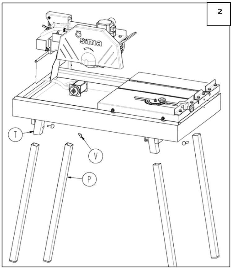
To place machine model in its normal position, it is necessary to place the four legs in its frame (P, Fig.2) putting them up in the corresponding leg supports (T, Fig.2) of the tray using screws provided.
3.2 FILLING THE WATER TRAY
The DAKAR PLUS models are designed to work with diamond disks cooled by water. Therefore, an important part of the frame is a tray intended to serve as the cooling water deposit pumped in a closed circuit to disk.
ATencion: Before plugging the machine to the electricity to effectuate any cutting operation, the water tray should be filled until the pump has been completely covered.
During cutting operations, a large amount of dirt is accumulated in the tray. Thus, you have to change the water as often as necessary to ensure the smooth functioning of the pump and the perfect cooling of the disk. The tray has a stopper to remove once you want to change the water.
4. ELECTRICAL PLUGGING AND ADJUSTING THE DISK ROTATION SENSE
Upon receipt of the machine, make sure the network electrical tension is adequate before plugging the machine. The electrical tension is to be found on the voltage indication next to the switch of the machine.
ATTENTION: Never plug the machine to electricity, in case the network power tension is not the adequate as the engine would undergo irreparable damages
Once you have realised the previous steps and before placing the disk and manipulate the motor, it is necessary to check and adjust the rotation of the motor axis correctly, you have to plug the machine to the electricity and start it up, watching the rotation direction that must be clockwise. If necessary and with three-phase motors, you can change the rotation direction swapping the two phase wires in the aerial or in the peg of the feeding extension cord.
If necessary, you will have to swap the conducting cables to change the rotation sense of the disk. Do this only with the machine unplugged from electricity.
ATTENTION: Never manipulate power supply cables or any other electrical equipment on the machine before you unplug the machine from electricity.
Once the disk rotation sense has been adjusted, you can mount the cutting disk.
5. MOUNTING AND DISmountING THE CUTTING DISK
The DAKAR PLUS models are designed to use segmented diamond disks and continuous rim disks either 300 or 350~mm of diameter
The cutting disks have different properties depending on the material to cut. Hence, an adequate selection of the disk increases the performance and guarantees a better result.
Make sure the maximal supported revolutions by the disk are equal or superior to those of the machine's engine.
5.1 MOUNTING/ REPLACING THE CUTTING DISK
The disk can be mounted or replaced as follows:
- Make sure the power supply cable of the machine is disconnected.
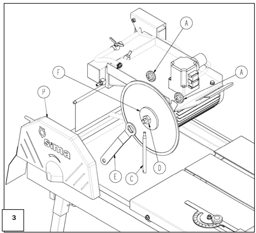
- Remove the disk safeguard (P, Fig. 3) of the cutting bridge of the machine loosening the screws that fix it. (A, Fig. 3)
- Introduce the hexagonal key (E Fig. 3) in the nut (D Fig. 3) Block the rotation of the axis inserting the pricker key in the bore placed outside (C, Fig.3), untighten the axis nut and remove the outer bridle (F, Fig.3).
ATTENTION: The nut is left-threaded
- Place the disk on its axis ensuring it is well centralised and perfectly located.
- Place the exterior bridle back and tighten the axis nut using the set of keys used before.
- Check the coupling between the disk and the bridles before tightening the nut.
- Place the safeguard back in its position and tighten well the screws fixing the cutting head.
- To dismount the disk, proceed in the inverse sense
ATTENTION: Remove all the used tools, making sure that all the elements of the machines have been mounted in the correct position.
-
You can plug the machine to the electricity.
-
Once the cutting disk has been mounted, check once again the disk rotation sense is correct, and comply with the before-mentioned procedure. This needs to match with the direction of the arrow marked on the disk and with the direction of the arrow graven on the disk safeguard.
6. ELECTRICAL EQUIPMENT
The electrical equipment of the Venus cutting tables manufactured by SIMA, S.A. has an IP54 protection degree.
The power supply on this machine has a low minimal tension bobbin to avoid any unexpected starting-up of the machine:
When there is a power cut or a fall of tension that causes the machine to stop, and once the normal power conditions have been re-established, the motor does not start until the green button is pressed.
6.1 SINGLE-PHASE MACHINES
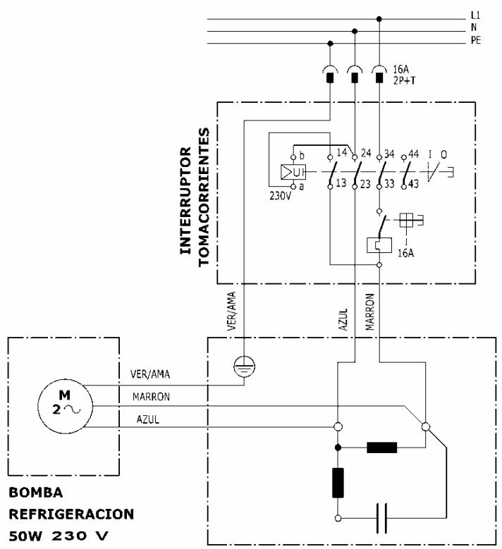
The extension cable used to feed the machine needs to have a minimum section of 3 × 1.5 mm^2 up to 25 meters long. For a superior distance 3 × 2.5 mm^2 can be used. In one of its ends, it is needed to connect a base normalised aerial of 16A 2P + T compatible with the machine switch and in the other end, one normalised aerial pin of 16A 2P + T compatible with switchboard exit.
6.2 THREE PHASES ELECTRIC MOTORS
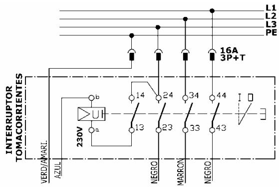
The extension cable used to feed the machine needs to have a minimum section of 4 × 1.5 mm^2 up to 25 meters long. For a superior distance 4 × 2.5 mm^2 can be used. In one of its ends, it is needed to connect a base normalised aerial of 16A 3P + T compatible with the machine switch and in the other end, one normalised aerial pin of 16A 3P + T compatible with switchboard exit.
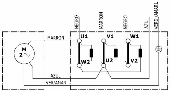
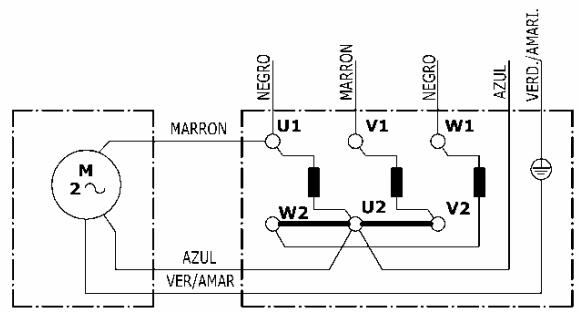
The three-phase DAKAR PLUS models leave the factory prepared to work at 400V.
When necessary to use a three-phase power tension at 230V , we need to swap the positions of the bridge plaques in the motor terminals box, as indicated in the following figure:
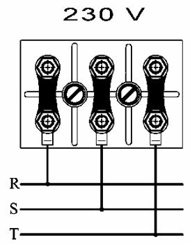
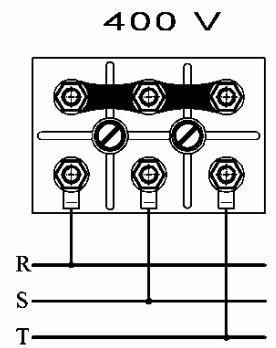
IMPORTANT: Unplug the machine off the electricity before you proceed with swapping the bridge plaques in the motor. Consequently, you have to change the indicative labels of feeding voltage so as to have the correct voltage indicated on the machine.
7. SEGURITY RECOMENDATIONS
The machines with electric motor should always be connected to a standard electrical box that has a circuit breaker and a Residual-current device in accordance with the characteristics of the engine:
2.2kw/3 CV, 230 V SINGLEPHASE 20A circuit breaker 20A/300mA Residual-current device
3kw/4 CV, 230V THREEPHASE , 20A circuit breaker 20A/300mA Residual-current device
3kw/4 CV, 400V THREEPHASE 15A circuit breaker 15A/300mA Residual-current device
VERY IMPORTANT: Always use earth plug before starting-up the machine.
Always keep protection elements and the safety protections in their correct positions.
- The damaged electrical cables should be urgently replaced.
- Unplug the machine from the electricity and never manipulate nor operate on the mechanical nor electrical elements of the machine while the engine is on.
- Never use the machine for purposes other than those it has been designed for.
Use normalised cables
- Make sure the feeding voltage is in accordance with the voltage indicated in the adhesive label on the machine.
- Make sure that the extension cords are not in contact with points of high temperature, oil, water, sharp edges.
- Also avoid trampling or crushing the cables by passing vehicles and do not put any objects on the machine.
- Do not use high pressure water to clean circuits or electrical elements.
ATTENTION: You are to follow all safety recommendations mentioned in the present user manual and comply with all labour risks prevention norms in every location.
8. MACHINE STARTING-UP AND USING INSTRUCTIONS
8.1 POSITION OF THE MACHINE AND THE OPERATOR, CONNECTION AND DISCONNECTION
The machine needs to be installed in well illuminated, stable and plane surface, free from any obstacles.
Before starting-up the machine, we should have gone through all necessary safety measures (electrical connection, stability, protections, etc...) as mentioned in the previous chapters.
When installing the machine, make sure the table on which it will be placed should be a horizontal, non bland surface.
This machine IS NOT TO BE USED UNDER RAIN AND ALWAYS WORK IN GOOD ILLUMINATION CONDITIONS.
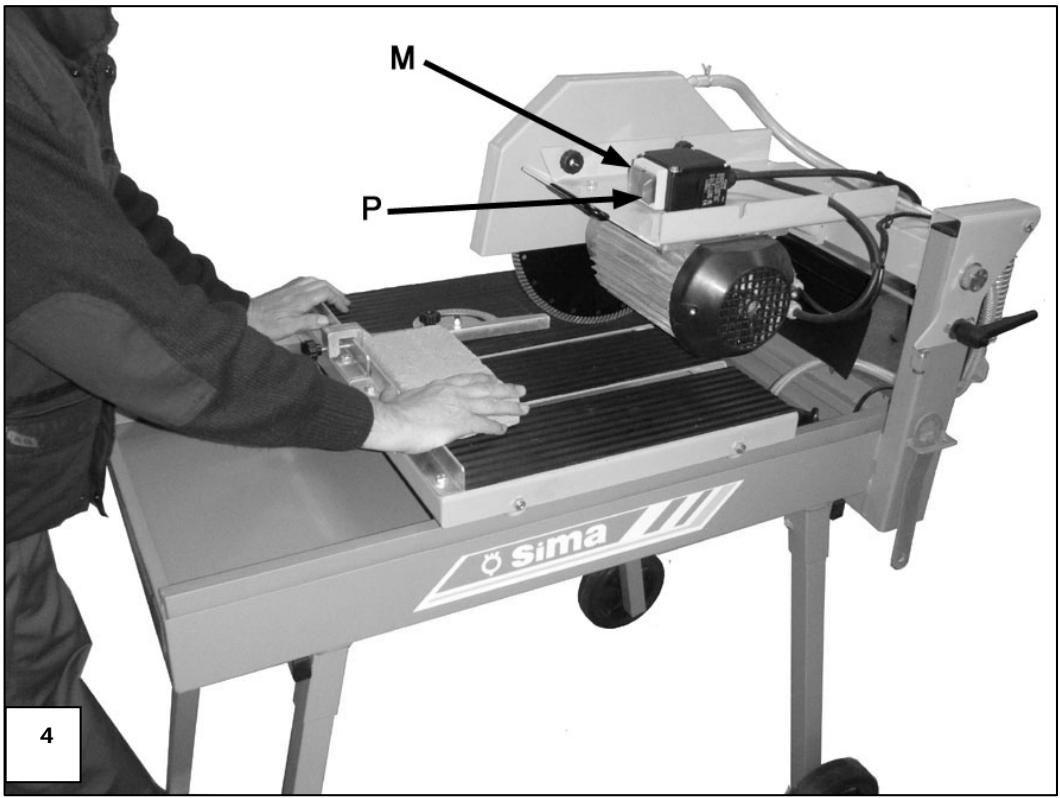
To start cutting, the operator should stand in front of the machine. In this position, the operator can easily manage the cutting head and the piece to be cut. He/she will also have easy access to the electrical plug. (Fig. 4).
Once the power supply cable is connected, the motor and the water puma start-up only by pressing the green switch button.
The machine can be stopped, simply by pressing the red switch button. (Fig. 4).
8.2 ADJUSTING THE HEIGHT OF THE CUTTING HEAD
The machine is delivered aligned and adjusted for a determined cutting height. If you wish to transform the machine from 0300 to 0350 or the opposite, you have to be careful with the height you want and change the position of the motor as you can cut the cart with the disk. To change the cutting height, proceed as follows:
ATENTION: This intervention must be effectuated only if the power supply is totally unplugged.
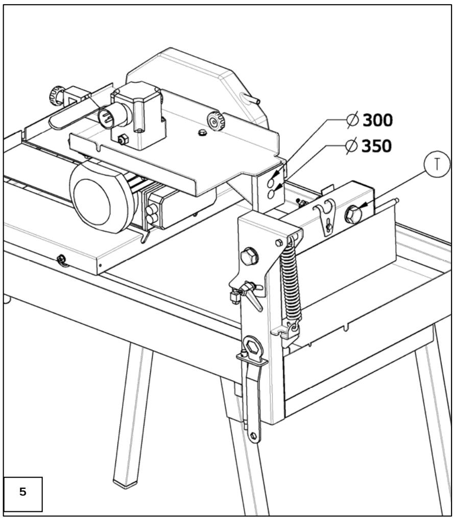
Once the engine has been unplugged from the electricity, loosen and remove the screws (T fig.5) fastening the cutting bridge with the lateral set squares.
2 Raise the motor platform to (Ø350) or lower it to (Ø300) sliding it with the flumes. Thereafter, tighten the screws pushing the platform on the end of the flumes as such that the cutting head remains well aligned. With this system, there is no need to align the disk each time you change the cutting height.
3 You can now plug the machine back to the electricity.
8.3 REALISING A STRAIGHT CUT
Straight cutting is realised as follows:
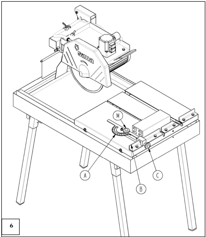
To make a straight cut will place the rule that accompanies the machine, on the top front of the machine (B, Fig 7), and slid to the point that we determine the extent to which it will cut the part. This position is fixed to the machine by pressing the corresponding lock screw (C, Fig.7). The piece to be cut is placed resting on the top front of the machine (B, Fig.7), the rule may be placed on either side of the piece as needed, and the court will run manually pushing the machine to drive.
Start slowly and progress according to grade the depth of cut and material hardness. An excessive advance may lead to a faulty cutting or blocking the disk.
The coolant pump is started simultaneously with the engine. Before approaching the material to make sure it receives the necessary water.
Let's place the adjustable angle ruler which is supplied with the machine on the front of the sliding cart (B, Fig.6) let it slip as wished. Then fix the ruler to the sliding cart with the nut. (M, Fig.10). Afterwards loose the knob (C, Fig.6) and turn the adjustable ruler (A, Fig.6) up to 0 positions and fix it again.
The material will be laying on the sliding cart (B, Fig.6) and the adjustable ruler (A, Fig.6). The adjustable ruler can be adjusted on any side of the material.
Place the piece to be cut on the cutting table making sure it remains stable and laying against the front ruler of the cutting table. (B Fig. 6).
Once the height of the cutting head has been adjusted and the piece placed on the cutting table, start-up the engine and make sure the cooling is adequate to the disk and material to cut. Using the handle that embodies the disk safeguard, (M Fig. 6) drag the cutting head until the disk touches the piece to cut. You need to start cutting slowly and maintain a constant progress in function of the material to be cut.
8.4 REALISING A 45^ CUT
DAKAR PLUS models have been design to performance either 90^ or 45^ cuts very easily.
8.5 REALISING A DIAGONAL CUT
Diagonal cutting is effectuated in the same way as a right cutting:
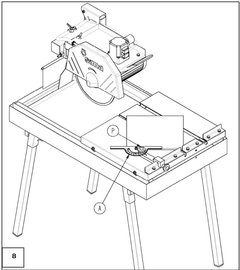
For a diagonal cutting, you need to use the ruler with a graduated semicircle (A, Fig.8) that is supplied with the machine. This ruler must rotate to look for required degrees to make the cutting. It has a blocking screw (P, Fig.8), to fix the desired position. Once the degrees have been selected in the semicircle, you place the piece to cut on the cutting table marking the face of the graduated ruler as well as the front ruler upper face(Fig.8).To complete the cutting, proceed as per the straight cut instructions.
8.6 CUTTING IN DOWNWARD MOTION
The design of the cutter DAKAR PLUS model allows cutting maintaining the sliding cart fixed and making progress with a downward motion of the cutting unit. This mode is very useful to make interior windows in one piece.
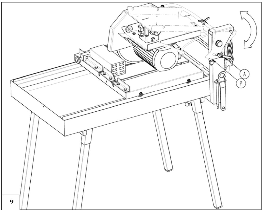
To make this type of cut we loosen the adjustable handle A, Fig.9 till the unit is freed and the internal spring tension will draw up its highest point
Then we will move the sliding cart with the work piece on to a position below the disc and proceed to cut holding the handle and pushing to cut down against the resistance of the spring.
The advance shall be adjusted depending on material hardness and depth of cut (Fig. 9)
Excessive reduction of the disk could potentially damage the sliding tray so the machine incorporates a screw cap (P, Fig.9) which is regulated so that the downward movement does not exceed the need to cut the media. Similarly this cap determines the position of the horizontal plane of the cutting head, which is a precondition to turn 45 degrees without causing a deflection of the disk.
8.7 SAFETY RECOMMENDATIONS
- DAKAR PLUS table saws are only to be used by familiarised people with its functioning
- Before starting up the machine please read the instructions and make sure safety norms are respected. Learn how to stop the machine in a fast and safe way.
- Place the machine on a plane surface. Connect the machine to the electricity only when you are sure of its stability.
-
Start the machine only when you have mounted the safety guards that come with the machine.
-
It is recommended to use safety glasses, safety boots, gloves etc. Please always use approved materials.
- Always use Individual Protection Equipment (IPE) in accordance with the type of work you are effectuating.
Prohibit strangers to access the place of work of the machine. - Work clothes are not supposed to have loose articles that can cling into movable parts of the machine.
- When you have to move the machine, unplug the electricity cables and block the moving parts of the machine.
Only the diamond blade specified in this manual should be used.
Always keep protection elements and the safety guards in their correct positions. - The damaged electrical cables should be urgently replaced.
- Unplug the machine from the electricity and never manipulate nor operate on the mechanical nor electrical elements of the machine while the engine is on.
- Never use the machine for purposes other than those it has been designed for.
Use normalised cables - Make sure the feeding voltage is in accordance with the voltage indicated in the adhesive label on the machine.
- Make sure that the extension cords are not in contact with points of high temperature, oil, water, sharp edges. Also avoid trampling or crushing the cables by passing vehicles and do not put any objects on the machine.
- Do not use high pressure water to clean circuits or electrical elements.
SIMA, S.A. is not responsible for the consequences possibly generated but the inadequate use of the materials cutting machine DAKAR PLUS model.
9. MAINTENANCE
The DAKAR PLUS table saws require a simple maintenance as per the following operations:
- Change the tray water and clean the machine as much as needed. The tray has a tap for this use. It is necessary to fill the tray with water until the pump is covered with water.
- Although the cooling pump has a filter cap, it may get in dirt and debris inside of the cut material to block the propeller. To prevent this, periodically run the pump in a container with clean water for several minutes. If necessary, unscrew the filter cap and clean the propeller until it turns freely.
- Remove all possible residuals of cut materials that can cling into the rolling tracks of the cutting bridge.
- Replace as soon as possible electrical cables that cause power cuts, breaking or any other disrepair.
- If the machine is not covered, wrap it with an impermeable cloth.
- At the end of each day, unplug the machine.
- Maintenance operations should be performed by people who the machine and its functioning.
ATENTION: before performing any maintenance or cleaning operations, the electricity cable should be unplugged.
In case you observe any anomalies or mal functioning, let a technician check the machine.
Take into account the safety recommendations mentioned in this manual.
It is prohibited to independently make any change in some parts, components or characteristics of the machine. SIMA, S. A. shall in no case be responsible for the consequences that may derive from a breach of these recommendations.
9.1 SUBSTITUTING A DETERIORATED DISK
The cutting disk is one of the most important elements of a cutting table. A disk in good condition is essential to get an optimal performance of the machine. Replace it when worn-out, twisted or cracked.
Do not use any kind of disk that is not specified in this manual and make sure the disk has the required characteristics of the maximum diameter, central drill diameter and the maximum number of revolutions supported.
Bear in mind that within the group of diamond disks, there are different types depending on the material to cut. Choose always the most appropriate to your case.
As mentioned before, we recommend you to use always SIMA ORIGINAL DISCS that meet the technical and safety requirements and are offered in a wide range that covers all the needs and facilitates the right choice.
9.2 ALIGNING THE DISK
The DAKAR PLUS table saw models are tested and seen perfectly in the factory before shipment. If for any unforeseen the disk is no longer aligned with the guides of the machine, it will produce a default cut. Therefore the machine will require a new alignment of the disc to the machine guides.
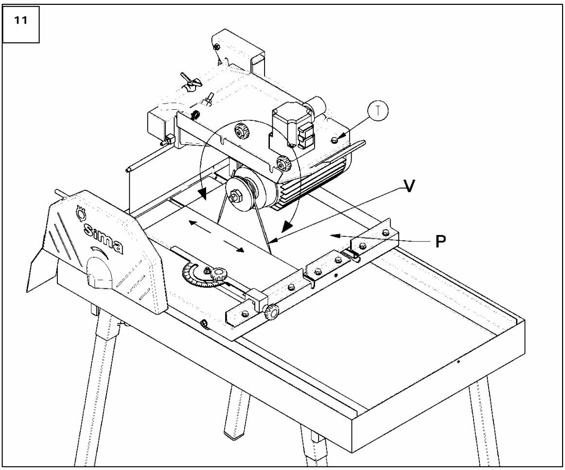
To perform this operation is necessary to provide a steel rod with 4 or 5mm diameter and 350mm long approximately sharpened at one end in the form of pencil-point (Fig. 8). Also need a piece of ceramic (tile or sandstone) (Fig.8) and white chalk. It will proceed as follows:
1 Unplug the machine from electricity and remove the disk safeguard.
2 Loosen the blocking controls (P Fig. 8) from both ends and with the square located on the cutting table and facing the front side of the disk, you need observe the parallelism of both.
Place the rod between the flanges for fixing the disk and tighten the axle nut, so that the pointed end of the rod friction with the work piece in the area marked with chalk.
- Move the sliding cart so that the rod makes a straight line on the tile.
Then turn the shaft so that the rod be on the opposite side (Fig. 8) move the tray in reverse way to the one perform before in order to draw a new line, this must match exactly with the first,
If both lines are mismatched, to loosen the screws on the blade spindle bearings leaving them with a pinch moderate (T, Fig.8) and adjust the position of this until we get the two on the chalk lines are coincident. Once achieved will turn to tighten the screws in the bearings.
9.3 ALIGNMENT GUIDES.
If you observe that the cut is not squared in reference to the supporting side of the fixed rules of the sliding cart it is possible that the guides were displaced. To correct the error, you must manipulate the screws that fix the guides to the plate (T, Fig. 9) and without removing the sliding cart you should be able to move the two guides together with the sliding cart making short displacements to the left or to the right until achieving a squared cut. Do not forget to fix the two guides with its screws again.
10. SOLUTIONS TO MOST FREQUENT ANOMALIES
| ANOMALY | POSSIBLE CAUSE | SOLUTION |
| Motor does not start up | Power supply fault | Check the power supply in the switch board. Check the position of the thermal magnet and the differential in the switch board. Make sure the extension cable is in a good state and well plugged in both ends |
| Damaged switch | Substitute it | |
| Blocked disk | Remove obstacles preventing the disk from turning | |
| Motor starts up very slowly and takes long to reach its revolutions | Damaged condenser. (Single phase motors) | Substitute it |
| Cutting power insufficient | Bluntness of the disk segments or diamond bands | Effectuate different cuts on an abrasive material (Sandstone, concrete, stone emery) |
| Inappropriate disk | Use appropriate disk for material | |
| Motor low potency | Let the motor be checked by technical service | |
| The cooling water does not reach the disk | Water level low in the tray | Fill in water to level |
| Pump blocked | Dismount the tape filter and clean it | |
| Pump damaged | Substitute the pump | |
| The pump water tape is closed | Open the water tape | |
| Disk premature damage | Insufficient cooling | Check the cooling |
| Excessive advance | Decrease the advance | |
| Inappropriate disk | Use appropriate disk for material | |
| Defective cutting | The machine is not aligned | Align |
| Disk deteriorated or worn-out | Change disk | |
| Inappropriate disk | Use appropriate disk for material | |
| Vibrations occurrence | Disk oscillation | Check the state of the disc and mount it correctly |
| Disk subjection defect | Make sure the bridles and the motor axis are well adjusted. Tighten well the nut. | |
| Wrap the disk | Change the disk |
11. TECHNICAL CHARACTERISTICS
| DATOS | DAKAR PLUS MONOFASICA | DAKAR PLUS TRIFASICA |
| Motor power (KW.) | 2,2KW | 3KW |
| Motor tension | 230V~ | 230V~/400V~ |
| motor R.P.M. | 2800 R.P.M. | |
| Water pump power | 50W | |
| Water pump tension | 230V~ | |
| Outer disk diameter (mm.) | 350 mm | |
| Inner disk diameter (mm.) | 25,4 mm | |
| Cutting length (mm.) | CON DISCO DIÁMETRO 300: 645 mm | |
| CON DISCO DIÁMETRO 350: 630 mm | ||
| Cutting depth (mm.) | CON DISCO DIÁMETRO 300: 75 mm | |
| CON DISCO DIÁMETRO 350: 100 mm | ||
| Water tank capacity (L.) | 43 LITROS (Con el nivel besoinario) | |
| Net weight (Kg.) | 66,4Kg | |
| DIMENSIONS LxWxH | 1080 x 686 x 1220 | |
12. WARRANTY
SIMA, S.A. the manufacturer of light machinery for construction possesses a net of technical services "SERVI-SIMA".
Repairs under warranty made by SERVI-SIMA are subject to some strict condition to guaranty a high quality and service.
SIMA S. A. guarantees all its products against any manufacturing defect; to take into account the conditions stated in the attached document "WARRANTY CONDITIONS". The latter would cease in case of failure to comply with the established payment terms. SIMA S.A. reserves its right to bring modifications and changes to its products without prior notice.
13. SPARE PARTS
The spare parts for the cutting table, model DAKAR PLUS, manufactured by SIMA, S.A. are to be found in the spare parts plan, attached to this manual.
To order any spare part, please contact our alter-sales service clearly indicating the serial number of the machine, model, manufacturing number and year of manufacturing that show on the characteristics plate.
To order any spare part, please contact our alter-sales service clearly indicating the serial number of the machine, model, manufacturing number and year of manufacturing that show on the characteristics plate.
14. ENVIRONMENT PROTECTION

Raw materials have to be collected instead of throwing away residuals. Instruments, accessories, fluids and packages have to be sent into specific places for ecological reutilisation. Plastic components are marked for selective recycling.

R.A.E.E. Residuals arising of electrical and electronic instruments have to be stored into specific places for selective collection.
15. DECLARATIONS ON NOISES
The acoustic level emitted by the MACHINE:
The level of vibrations transmitted to the hand-arm:
| MODEL | LEFT HAND m/ s2 | RIGHT HAND m/ s2 |
| DAKAR PLUS MONF. | 5,71220387313 | 4,71851454008 |
| DAKAR PLUS TRIF. | 5,71220387313 | 4,71851454008 |
17. ELECTRICAL SCHEMES
DAKAR PLUS
END USER FORM
MACHINE DETAILS
NUMBER PLATE
CLIENT DETAILS
NAME
ADDRESS
POSTAL CODE AND CITY
PROVINCE/COUNTRY
TEL.:
Fax:
DATE OF PURCHASE
Signature and stamp of the selling party
Client signature
WARRANTY CONDITIONS
1.) SIA, S.A. fully guarantees all its products against defects in design, taking responsibility in the repairs or the faulty equipment for a period of ONE year from the original date of purchase. The date of purchase must appear on the warranty voucher enclosed.
2.) The warranty covers exclusively labour, repair and substitution of the faulty parts, the model and serial number of which must show on the warranty certificate.
3.) Transport, stay and food expenses before arriving to SIMA S.A., will be covered by the client.
4.) The warranty does not cover any damage caused by the normal wear, undue usage, overloading, inadequate installation or bad conservation of the machine.
5.) All repairs under WARRANTY will solely be effectuated by SIMA, S.A. or by its authorised dealers or repair centres.
6.) This Guarantee will be invalid in the following cases:
a) Any Warranty certificate manipulation or modification
b) Repairs, modifications or substitution of any part of the machine by unauthorized parties by SIMA S.A technical department.
c) The non-approved installation of devices by SIMA S.A technical department.
7.) SIMA is not responsible for any damages caused by the failure of the product. This includes, but not limited to, annoyances, transport expenses, telephone calls and loss of personal goods or commercial benefits, as well as the loss of pay or salary.
8.) Faulty thermal or electrical motors under warranty have to be sent to SIMA S.A or its authorized technical service in the country.
9.) To be benefit from the warranty, the warranty certificate must be at SIMA S.A premises within 30 days from the purchasing date. To claim the warranty, the purchase invoice has to be attached stamped by the dealer including the serial number of the machine.
FORM TO RETURN TO MANUFACTURER
DATOS MAQUINA
NUMBER PLATE
DATOS COMPRADOR
NAME
ADDRESS
POSTAL CODE AND CITY
PROVINCE/COUNTRY
TEL.:
Fax:
E-mail:
DATE OF PURCHASE
Signature and stamp of the selling party
Client signature
WARRANTY CONDITIONS
1.) SIA, S.A. fully guarantees all its products against defects in design, taking responsibility in the repairs or the faulty equipment for a period of ONE year from the original date of purchase. The date of purchase must appear on the warranty voucher enclosed.
2.) The warranty covers exclusively labour, repair and substitution of the faulty parts, the model and serial number of which must show on the warranty certificate.
3.) Transport, stay and food expenses before arriving to SIMA S.A., will be covered by the client.
4.) The warranty does not cover any damage caused by the normal wear, undue usage, overloading, inadequate installation or bad conservation of the machine.
5.) All repairs under WARRANTY will solely be effectuated by SIMA, S.A. or by its authorised dealers or repair centres.
6.) This Guarantee will be invalid in the following cases:
a) Any Warranty certificate manipulation or modification
b) Repairs, modifications or substitution of any part of the machine by unauthorized parties by SIMA S.A technical department.
c) The non-approved installation of devices by SIMA S.A technical department.
7.) SIMA is not responsible for any damages caused by the failure of the product. This includes, but not limited to, annoyances, transport expenses, telephone calls and loss of personal goods or commercial benefits, as well as the loss of pay or salary.
8.) Faulty thermal or electrical motors under warranty have to be sent to SIMA S.A or its authorized technical service in the country.
9.) To be benefit from the warranty, the warranty certificate must be at SIMA S.A premises within 30 days from the purchasing date. To claim the warranty, the purchase invoice has to be attached stamped by the dealer including the serial number of the machine.
Déclaration "CE" DE CONFORMITE
SIMA, S.A.
CONDITIONS DE GARANTIE
CONDITIONS DE GARANTIE
Directivas 2006/95/CE; 2004/108/CE; 2000/14/CE; 2002/44/CE; 2002/95/CE;
2002/96/CE
POL. IND. JUNCARIL, C/ALBUÑOL, PARC. 250
18220 ALBOLOTE (GRANADA)
Telf.: 34 - 958-49 04 10 - Fax: 34 - 958-46 66 45
DEKLARACJA ZGODNOSCI "WE"
SIMA, S.A.
DEKLARACJA ZGODNOSCI "WE" 3
1. INFORMACJE PODSTAWOWE 5
2. OPIS OGOLNY MASZNY. 5
2.1 SYMBOLE 6
2.2 TRANSPORT 6
3. INSTRKCJE MONTAZU. 6
3.1 MONTAZ MASZNY 7
3.2 NAPELNIANIE ZBIORNIKA 7
4. PODŁACZENIE DO SIECI ELEKTRYCZNEJ I DOPASOWANIE KIERUNKU
OBROTOW 7
5. MONTAZ I WYMIANA TARCZY TNACEJ 7
5.1 PROCEDURE ZAKLADANIA BADZ WYMIANY TARCZY TNACEJ. 7
6.WYPOSAZENIEELEKTRYCZNE 8
6.1 MASZYNY Z SILNIKIAM JEDNOFAZOWYM 8
6.2 MASZYNY Z SILNIKIAM TROJFAZOWYM 8
7.ZASADY BEZPIECZENSTWA 9
8. INSTRUKCJE URUCHOMIENIA I UZYTKOWANIA 9
8.1 POZYCJA MASZYNI I OSOBY JA OBSLUGUJACEJ. WŁACZANIE I WŁACZANIE 9
8.2 REGULACJA WYSOKOSCI 9
8.3 CIECIE POD KATEM PROSTYM 10
8.4 CIECIE POD KATEM 45° 10
8.5 CIECIE PO SKOSIE 10
8.6 CIECIE Z OBNIZENIEM GLOWICY 10
8.7 ZALECENIA BEZPIECZENSTWA 11
9. KONSERWACJA 11
9.1 WYMIANA ZUZYTEJ TARCZY 12
9.2 USTAWIENIE NACHYLENIA TARCZY 12
9.3 REGULACJA LINIOWOSCI TARCZY. 12
10. ROZWIAZANIE NAJCZESTSZYCH PROBLEMOW 13
11. OPIS TECHNICZNY 14
12. O GWARANCJI 15
13. CZESCI ZAMIERNE 15
14. OCHRONA SRODOWISKA 15
15. DEKLARACJA POZIOMU HAŁASÖW. 15
16. DEKLARACJA POZIOMU WIBRACJI. 15
17. SCHEMAY ELEKTRYCZNE 16
CERTYFIKAT GWARANCJNY 22
1. INFORMACJE PODSTAWOWE.
8.1 POSIZIONE DELLA MACCHINA E OPERAIO. ACCENSIONE ED ARRESTO
POL. IND. JUNCARIL, C/ALBUJOL, PARC. 250
18220 ALBOLOTE (GRANADA)
Telf.: 34-958-49 04 10 - Fax: 34-958-46 66 45
2004/108/CE; 2000/14/CE; 2002/44/CE; 2002/95/CE; 2002/96/CE
Pon3BeHOBCOTBETCTBnC HOpMaMn:
5. YCTAHOBKA I CHYTNE PEXKUJIeTo DNCKA 7
5.1 YCTAHOBKA IJIN 3AMEHA PEXUSEO DINGKA
6. 3JIeKTPnueCKOE OCHAUHNE 8
6.1 OndHOΦA3HbI IxBnΓATEJIb 8
6.2 TPEXΦA3HbI I dBVΓATEJIb 8
7. PEKOMEHДAUZNI NO TEXHNIK E3ONACHOCTN 9
8. INHCTPYKUNIPO 3ANYCKU CTAHKA I ERO 3KCNJYATAUNI 9
8.1 NOJIOXEHNE CTAHKA I ONEPATOPA. BKJIIOUeyHNE/BbIKIIOUeyHNE 9
8.2 PEGYJINPOBKA BbICOTbl 9
8.3PE3KAIPOIINPRAMbIMYJLOM 9
8.4PE3KAIPOJyFJOM 45^ 10
8.5 PE3KA IIO DnAFOHAJI.. 10
8.6 PE3KA C ONYCKAHNEM CYNIOPTA 10
8.7 PEKOMEHDAUINIPO TEXHNIKE B3OJNACHOCTN 10
9. TEXHnueCKOE OBCJyXnBAHne 11
9.1 3AMEHA IOBPEKDEHHOFO DnCKA 11
9.2 HACTPOIKA YIJIA HAKLOHA DNCKA 12
9.3 BbIPABHINBAHNE INCKA HAPBABJIIOUX 12
10. YCTPAHEHNE HANBOJEE YACTbIX HENOLADOK 13
11. TEXHnueCKne XAPAKTEPNCTIKN 14
12. TAPAHNTNHBIE O6RA3ATEJbCTBA IN KOMPJIeKTIyIOUJIe. 15
13. 3APACHbIE DETAJIH 15
14. 3AUHTA OKPYKAIOUcEIN CPeIbI. 15
15. yPOBEHb ⅢyMA. 15
16. YPOBEHb IPEPEDABAEmbbIX BnBPAuN. 15
17. 3JIeKTPOCXEMbl 16
TAPAHNTHbI CEPTNΦNKAT 22
1.ObuA HΦOPMaζη.
BHIMAHNE:пелднанлOMЗКПЛУАцIN O6OpYIOBaHnB BHIMaTeIbHO O3HaKOMbTecb C copejXaHnem daHHo nHCTpyKcN.
AO CIMMA 6laogadapit Bac 3a okazahhoe doberne K haasei npodykun n 3a npno6peTeHne KAMHEPE3HO T OToJA moDen DAKAR PLUS.
B daHnom pykoBoOCTBe no 3KcPlyatauun coedeXnTcra Bc Heo6xOIma HhOpMaunno yctahOBKe obopyoBaHnra, er0 3KcPlyatauun, texHnueckomy 0cbnyxmbaHnIO u, B cIyae Heo6xoDmocStn, no er0 peMOHTy. TaKke B hem npBedeHb BCE acneKtbl, KOTopbIE MOrY T nobJrTB Ha 6e3OnaChocTb n 3dOpOBbe pa6OuXv B npouceCce OcyueCTBJIeHnna IIO60n 3 yka3aHHbIX MaHnPyJauun C o6OpyDoBaHnem. YeTKoe CneIOBaHne npBedeHNbIM IHCTpyKzmaM oecneuHT hadEcxHyo pa6Otu obopyoBaHnra n IpocToTy erO texHnueckoro 0cbnyxBaHnra.
I03TOMy IIO6oe IINIO, OTBeTCTBENHOe 3a EKcNpyatauHIO, TexHnueckoe 6cbnyxnbAHne IIN peMOHT yka3aHHoro 6obopyoBaHn, DOJIHXHO BHNMaTeNbHO pOouNTaTb daHHoe pyKOBOdCTBO.
PekomeHnyetcA depkaTb daHHoe pyKOBoCTBO no 3KcnIyatauHN B Ierko doCTynHom MecTe TaM, rde nCnoJIb3yETcO6OpUdoBaHne.
2. OБICIЕ ONИСAHNE MAJIINHbl.
Kamhepe3HbIe cToJI npOn3BODCTBa AO CIMA, moJeI N DAKAR PLUS, cneuaJIbHO pa3pa60TaHbI npOn3BODATcI dJIpe3Kn B npOceCE CTpOHTeJIbHbIX pa6OT KAMn I pyrNX CTPONTeJIbHbIX MaTePnaJIOB, IMeUoIx, nMeHbSeMpe, ONDy pa6OuyIO NOBepXHOCTb (KaFen, TeppauzO (BeHeuHaNcKa Mo3Anka), KnpNmu, MpaMOp, rpaHnT, KepAmnueeckA nn 6eTOHHa PnITa, KAMEHNO-KePamnueeckoe N3dEJIne.....). PexJuA qactb pndctabJETc o6oI aIma3HbI dNCK, npINBOIMbI B DeIcTBNe 3LeKTPoDBnRAteJIem IOXJaDaeMbI BOoI, KOtOPa NOdaETcC NOMOsbIO He6Obloro 3LeKTPnueeckoTO Hacoca. PpOdBnXeHne MaTePnaIa OCyueCTBnAE Tc BpyHyIO PyTeM TOkAHHa KapeTKN, Ha KOTopo PA3MeUeH MaTePnaI.
BepHyTb Ha MeCTO 3aunTHbI KOxUx I 3aTAYtB DePKaTeI, KpeIaIe erK CynPiOpTy.
YTo6bI CHaTb DnCK, BbIIOJIHInTe BCE DeIeCTBnB B O6paTHOM nOpJKe.
BHHMAHNE: y6epnte nCnoIb3OBAHHbIe INHCTpyMeHTbI n y6eIITecb, YTO BCE DeTaJI N CTAHka pa3MeIeHbI Ha CBOIX MecTax.
MOXHO BKJIIOHTb CTaHOK BCetb
UcTahOBuB pexyun nnck, cHOba y6eDntecb, yTo hAnpaBHeHne BpaSeHHn COBnadaaET C HApBaNHeHm, YKa3aHHbIM CTpeNKo, n306paXeHHo Ha dncke, n CTpeJIko, n306paXeHHo Ha npdeOxpaHnteJe.
6. 3JIeKTPnueCKOE OCHaUeHne
3JIeKTPoO6OpUdoBaHne, KOToPbIM yKOMnIeKTOBaHbI KaMHepe3HbI cTahKn BALI, npOn3BODmblE AO CnMA, IMeet yPoBeHb 3aunTbIP54.
UTeencelbHoe rHe3do C nepeKJIouaTeIeM, Upe3 KOtOpoe ocUyIeCTBJIeTcN OJaA ToKa, BkJIouaET B Ce6a KaTuShky Hn3KOrO HanpJxKeHn, UTO N03BoJIeT n36EkaTb HEnpeDbUeHnHO 3aNyCka 6opdyoBaHn.
B clyuae npekpaueHnnoaun 3JeKtpo3Heprnn nnnaeHnHa npjaKeHn, KOtOpoe BblOBeT OTKluoyehne CTAHka, noCne BocctaHOBHeHn HOpMaJbHbIX ycIobn noaun 3JeKtpoNTaHn HbNraTeIb He 3anyCTntc noka CHOba He 6ydet Haxata 3eJeHn KhONKa BkJIoueHn.
6.1 OДНΟΦΑ3HBIДВИΓATEЛь
MnHmAlbHoe nonepueHoe ceeHne Ka6eYdInHHTeJI, nCOnJb3yeMoTO dJIy NITaHnOBOpdyoBaHnO,doJXHO 6bIb paBHO 3x1,5 MM2 npi nnHe Ka6eNgo 25 MeTPOB. Jn Ka6eNgo 60bWeJ nnHbMI HmHmAlbHoe nonepueHoe ceeHne DOnJxHO 6bITb paBHO 3x2,5 MM2. C kaxdoRo KOHca OH doJONKeH mMeTb HopMaINIOBAHHU BnKU 16A 2P+T, n3 KOTOpbIX OHa DoJXHa 6bITb COBmecTIma co StenCeJIbHO pO3eTKoI CTAHka, a dpYra - co StenCeJIbHO po3eTKoI 16A 2P+T POnaun 3LekTpOHTAHn.
6.2 TPEXΦA3HbIДВИRATEЛь
JIIO6bIe DeiCTBnA CO CTaHkOM DoJXHbI OCyUeCTBnTbCpN BbIKLIOUeHHOM DBrTaTeNe I OTCOeINHeHHOM Ka6aIe NiTaHn. He 3a6yDbTe NOLHOCTbU y6paTb BCE INHCTpyMeHTbl, INcNoJIb3OBaBUnecr Pn TExHNueckOM 06cIyXuBaHn.
B clyuae obnapykeHn IepeKToB nI HneIolaK B pa6oTe cTahKa Heo6xoDmO o6paTntbC K cIeuaNtCy IIO texHnueckomy 6cIyXuBaHnIO dI npOBepKn pa6oTbI cTahKa.
Bcerda cneyuTe yHtBbAtepeKoMeHdaZnno TeXhNke 6e3OanachocTn, npuBeHeHHbE B daHHOM pyKOBOdCTBe.
Ponb30BaTeJIIO 3aIpe7aEcTcA cMOCTOReIbHO BHCnTb N3MeHeHnB DeTaII, 3JeMeHTbI HInxapakTepcntKu CTAHka. AO CIMA He HeceT HnKaKoI OTBeTCTBeHHocTn 3a IocJIeDCTBnA, Bbl3BaHHbIe Hec6JIouDeHnEm DaHHbIX peKomeHdaIi.
9.1 3AMEHA NOBPEKDEHHOFO DNCKA
Pexyun nnck k ybnctc oHn m n3 hau6olee Baxhblx 3JeMeHTOB KAMHepe3HOrO cTahka. IJnyocn Hauynuwe npOn3BODntelbHOCTN cTahka Heo6XoDmIO pndepKJBaTB dNCK B XopoWem COCTOHN. IpOn3BOUInTe 3aMeHy dncka, Korda OH n3HOWeH, NCKpNBLeH nIIN IMeET TpeUnHbl.
He nCnoJIb3yIte HnKaKne DpyRne TINbI dNcKOB, KpOme yKa3aHbIX B daHHOM pyKOBoJCTBe, cIeInte 3a TeM, UTO6bl XapakTePrcNTIKN DNCKA COOTBeTCTBOBaJIH Heo6xOdMbIM 3HaueHnAm MaKcImaJIbHOrO dNaMeTpA, dNaMeTpA BHTpeHHeRo OTBepCTnI MAKcImaJIbHOrO uCnla o6OpOTob.
ImeTe B BVdy, yTO cpei aJMa3HbIX DNCKOB BblJeJIaOTcpa3JIuHbIe TINbI B 3aBNCUMOCTN OT MaTePnAna, KOtOpB I pEiNoLaeraTc pe3aTb. B KaJDom KOHKPeTHOM Clyuae Bbl6upaIte Han60Jee PoJxOJauni DNck.
B CBa3n C BbIeU3NoJHbIM peKOMeHnyem Bam BCerda nCnoJIb3ObaTb OPINHAAJIbHbIE DNCKN CIMA, KOtOpbIe OTBeuAOT BCM Heo6XoDImbIM TexHnueckm Tpe6oBaHnAm N Tpe6oBaHnAm NO TexHnke 6e30NaChocTN. AO CIMA npedlaeraet uPOKyIO rAMMy dNcKOB, CNOC6HyIO yOBoJIeTBOpNTb BCM nOTpe6HoCTaM, UTO o6JIeYaET Bbl6op POnxOJaero DnCKa.
9.2 HACTPOIKA YIJIA HAKLOHA DINGKA
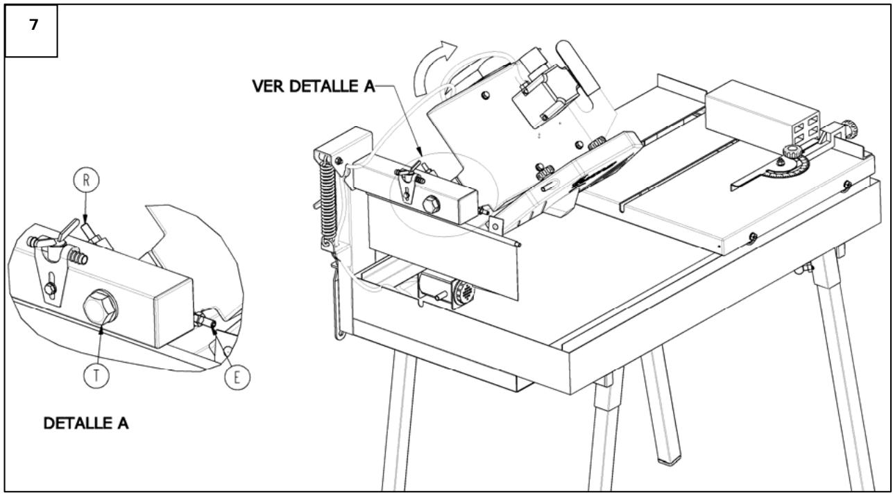
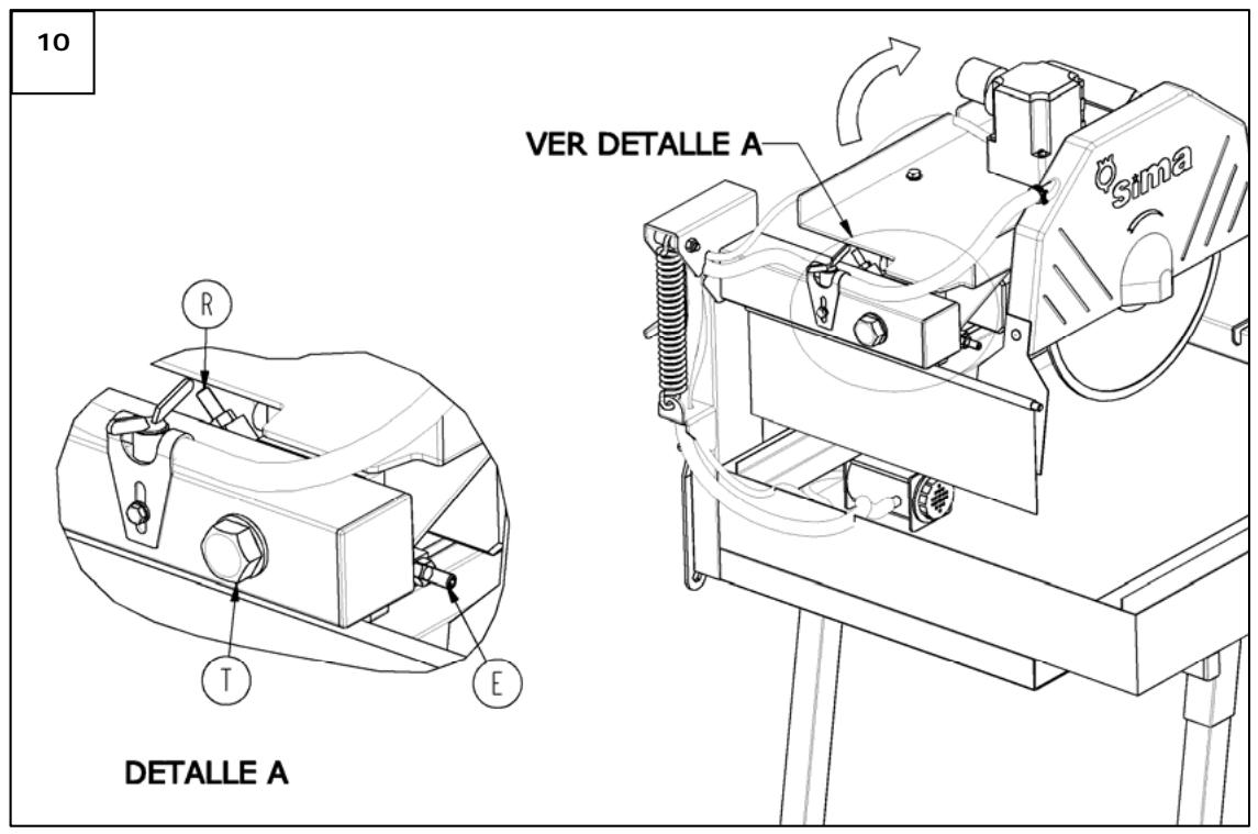
Kamhepe3hble cToIb moeJn DAKAR PLUS oTpeylnpoBaHbHa 3aBoTe TaK, yTo6bl nOLOXeHn 90o n 45^ coBnaadann, kOrda cynnpot fKnckpyet cneuaJIbHbIe ynopbl (R, E Fig. 10). Ecnu n3-3a HeoxndaHnro ydapa nn no npryo npuHne nOLOXeHn eYnpob Hapuyinocb, Heo6xoDmO oTpeylnpoBaTb nx nOLOXeHn:
Ocna6bTe KpeJexHbI 60T (T, Pnc.10), qTo6bI Ocbo6oDntb cyNnOpT, n HauInTe noLoXeHne dNscKa 90^ c NmOouy yrnomepa, coOTHOcC cyNnOpT n IInueByIO CTOpOHy DnCKa. B Cnyae Heo6xOIMOCST Ocna6bTe stnΦT -ynop (E, pnc.10), do tex nop , noka He DoCTNRHe TnoLKeHn 90°. Korda yroI BBCTaBLeH, 3aTaNte yKa3aHHbI mTnΦT noka OH He cOpNKoCHETc C cyNnOPTom. TAKIM o6pa3OM, 6bl BBCTaBLeH 3aHOBO yrol 90^ n 3aФHKcnpOBAH ynop, erO orpaHnUBAIoUoi.
Дя рergyларови пооженя 450 takIM ке obpa3OM nobepHnte cyllnoptВ npOTNBONIOJXHOM HanpaBJIeHn, Tolyko Tepepb pa6oTaIte C uTnФTom (R, pnc.10), tak KaK OH YBnEeTcYnpOM, orpAHuNBAUOUM 3TOT yroJ.
9.3 BbIPABHNBAHNE DnCKA N HAnPABJIIOxN
Kamhepe3hble cToIb DAKAR PLUS BbipabHnBaIOCTc n npOBepaIOc Ha 3aBoe nepeo OTnpabkoj. Ecn no KaokJ-To npuHHe nnck nepectaJI 6bITb BbIPOBHeH OTHocHTenbHO HappaBIAIOxN KapeTkn, OH 6ydet DeNaTb deΦeKTHbI pa3pe3, pOToMу Heo6XoDmO CHOba BbIPOBHraT bNCK n HappaBIAIOxne.
POL. IND. JUNCARIL, C/ALBUNOL, PARC. 250
18220 ALBOLOTE (GRANADA)
Telf.: 34 - 958-49 04 10 - Fax: 34 - 958-46 66 45