VMCC1 - TV Mount SANUS - Free user manual and instructions
Find the device manual for free VMCC1 SANUS in PDF.
| Product type | Center speaker bracket for wall mount |
| Brand | SANUS |
| Model | VMCC1 |
| Compatibility | SANUS wall mounts VMSA, VMAA, VMAA18, VMAA26, VMDD, VMDD26 |
| Material | Steel |
| Color | Black |
| Adjustable width (center-to-center) | 3.8 cm to 39.4 cm |
| Adjustable depth | Yes, via front/back brackets |
| Adjustable height | Yes, via extending arms |
| Maximum weight supported | 15 kg (estimate) |
| Tools required | Phillips screwdriver, adjustable wrench |
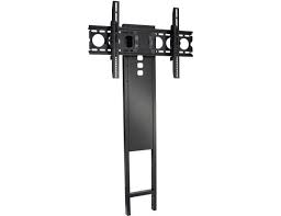
| Wall mounting | On existing wall mount (not included) |
| Included parts | Extensions, brackets, support bar, bolts, spacers |
| Safety | Read warnings, call a professional if necessary |
| Maintenance | Clean with a dry cloth |
| Repairability | Spare parts available via SANUS |
| Warranty | Consult SANUS |
Frequently Asked Questions - VMCC1 SANUS
User questions about VMCC1 SANUS
0 question about this device. Answer the ones you know or ask your own.
Ask a new question about this device
Download the instructions for your TV Mount in PDF format for free! Find your manual VMCC1 - SANUS and take your electronic device back in hand. On this page are published all the documents necessary for the use of your device. VMCC1 by SANUS.
USER MANUAL VMCC1 SANUS
International Assembly Instructions for model VMCC1
SANUS SYSTEMS
THE UNION OF FORM AND FUNCTION
Assembly Instructions for Model: VMCC1
Thank you for choosing the Sanus Systems VMCC1. The VMCC1 is designed to mount a center channel speaker below a Sanus VMSA, VMAA, VMAA18, VMAA26, VMDD or a VMDD26 Flat Panel Wall Mount.
Safety Warning: If you do not understand these directions, or have any doubts about the safety of the installation, please call a qualified contractor or contact Sanus at 800.359.5520 or www.sanus.com. Check carefully to make sure that there are no missing or defective parts. Our customer service representatives can quickly assist you with installation questions and missing or damaged parts. Replacement parts for products purchased through authorized dealers will be shipped directly to you. Never use defective parts. Improper installation may cause damage or serious injury. Do not use this product for any purpose that is not explicitly specified by Sanus Systems. Sanus Systems can not be liable for damage or injury caused by incorrect mounting, incorrect assembly, or incorrect use. Please call Sanus Systems before returning products to the point of purchase.
Required Tools: Phillips screw driver and crescent wrench.
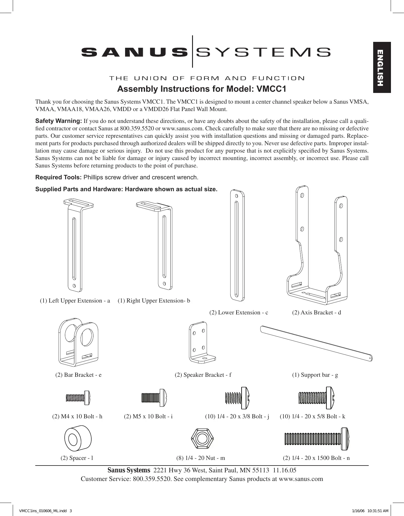
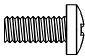
Supplied Parts and Hardware: Hardware shown as actual size.
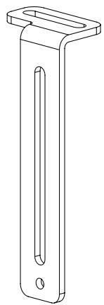
(1) Left Upper Extension - a
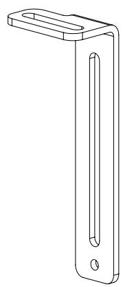
(1) Right Upper Extension- b
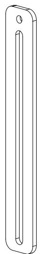
(2) Lower Extension - c
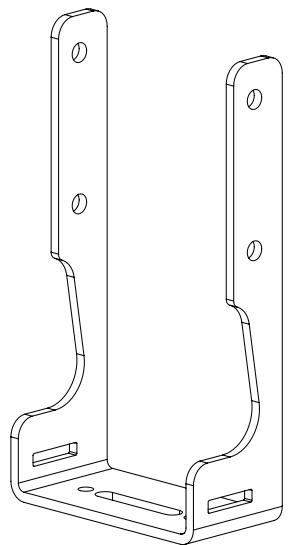
(2) Axis Bracket - d
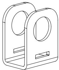
(2) Bar Bracket - e
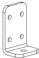
(2) Speaker Bracket - f
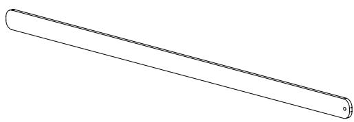
(1) Support bar - g
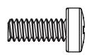
(2) M4 x 10 Bolt - h
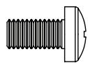
(2) M5 x 10 Bolt - i
(10) 1/4 - 20 × 3/8 Bolt-j
(10) 1/4 - 20 × 5/8 Bolt - k

(2) Spacer - 1

(8) 1 / 4 - 20Nut - m
(2) 1 / 4 - 20 × 1500 Bolt - n
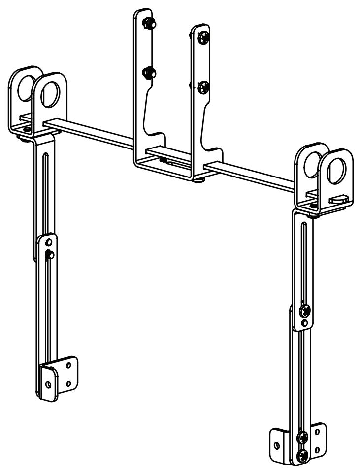
For assembly information for the VMSA, VMAA, VMAA18 and VMAA26 see the Steps 1 through 6. For assembly information for the VMDD and VMDD26 see Steps 7 through 12.
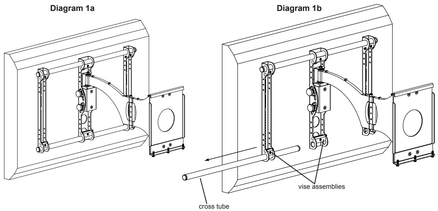
Step 1: Remove mount from Wall Plate and remove lower Cross Tube from the mount assembly.
Remove the mount from the wall plate. Loosen the Allen Bolts in the lower three Vise Assemblies and remove the lower Cross Tube from the mount assembly. See Diagrams 1a and 1b below.
Step 2: Add Axis Brackets
Position the Axis Bracket (d) so it fits over the Axis Assembly on the mount. Insert a 1/4 - 20 × 5/8 Bolt (k) through the Axis Bracket, Axis Assembly and into a 1/4 - 20 Nut (m). Repeat process until the Axis Bracket is secured with four 1/4 - 20 × 5/8 Bolts and four 1/4 - 20 Nuts. Tighten each Bolt with a phillips screw driver until secure. See Diagram 2 below.
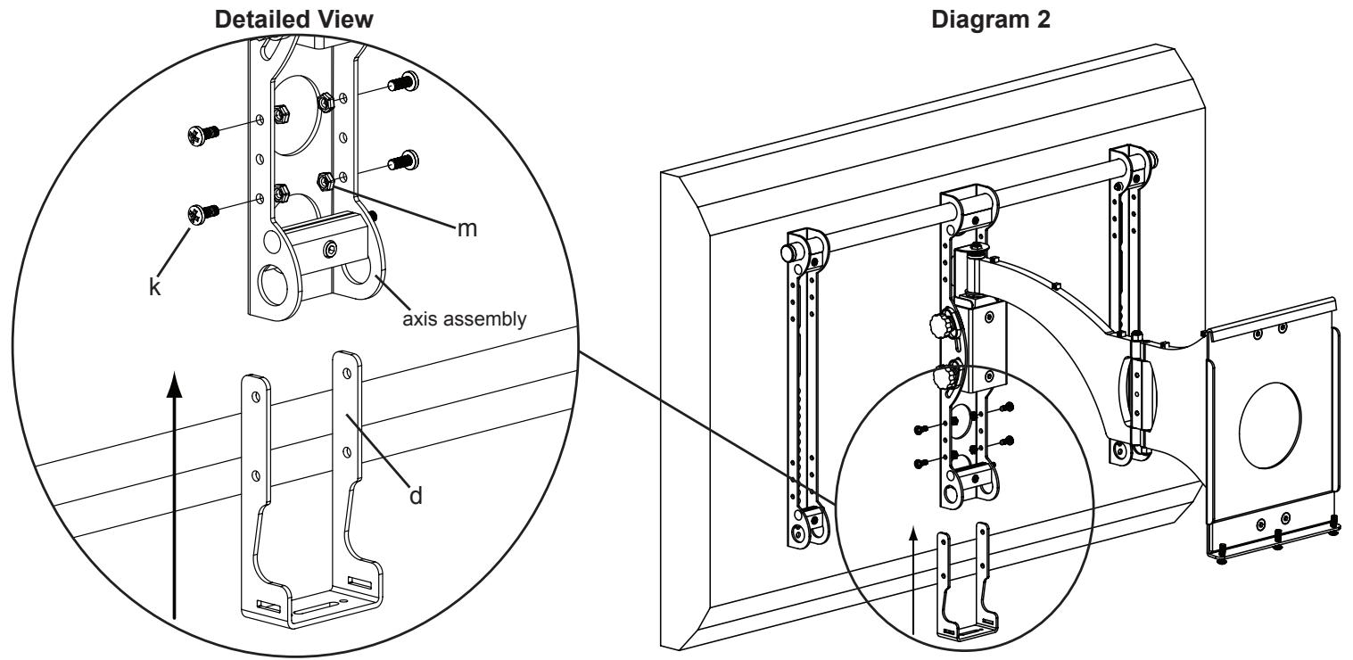
Step 3: Add Bar Brackets
Slide the lower Cross Tube through the Bar Bracket (e), the Axis Assembly, a second Bar Bracket and through the second Monitor Bracket. Tighten all three Vise Assemblies secure the Cross Tube once it is slid through the second Monitor Bracket. See Diagram 3 below.
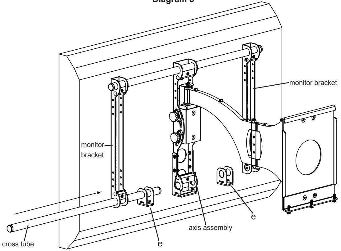
Diagram 3
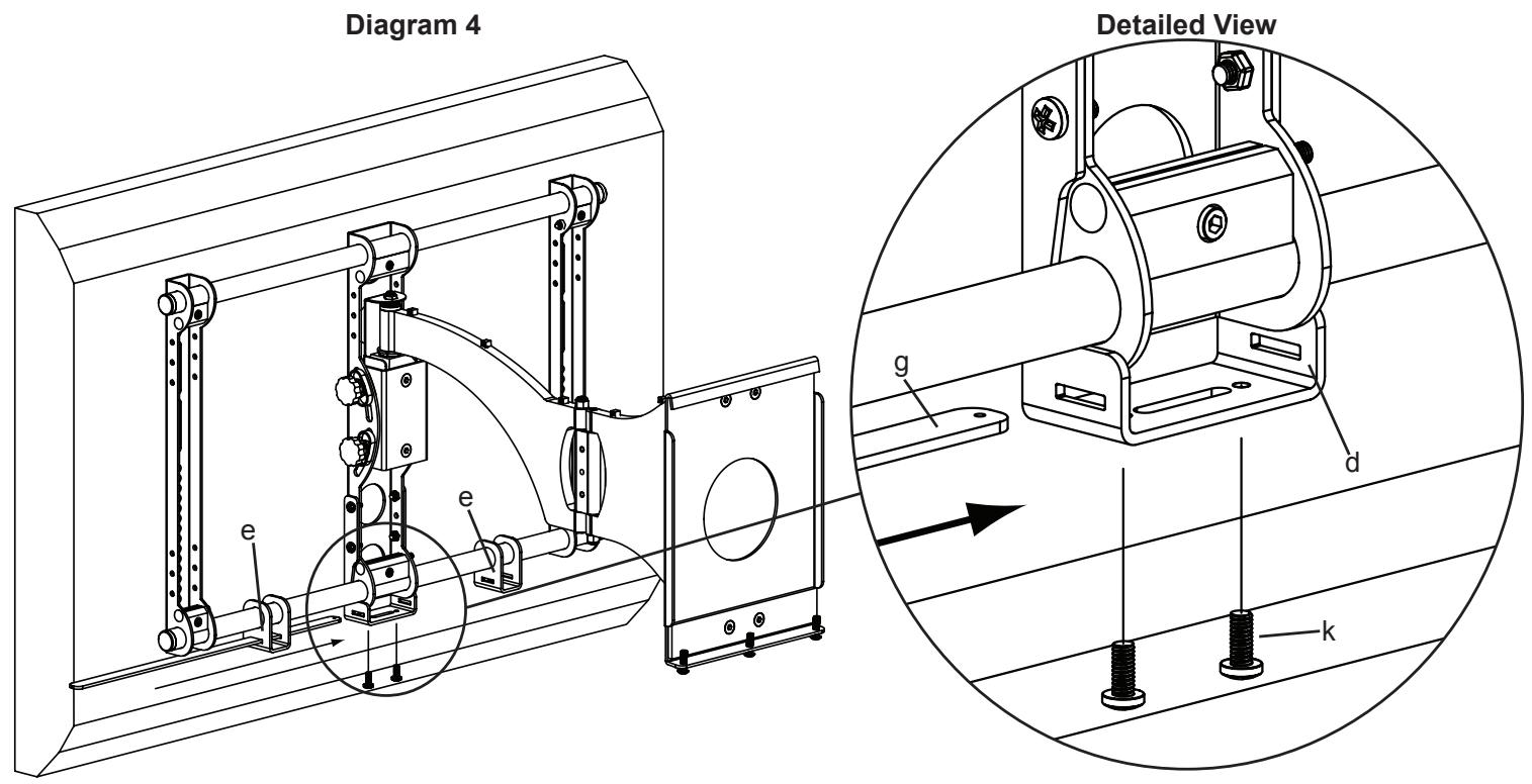
Step 4: Add Support bar
Slide the Support Bar (g) through the Bar Bracket (e), Axis Bracket (d) and through the other Bar Bracket. Make sure the Support Bar is centered on the wall mount. Thread each 1/4 - 20 × 5/8 Bolt (k) through each hole in the bottom of the Axis Bracket until they bottom out in the Support bar. See Diagram 4 below.
Step 5: Configure Speaker Attachments
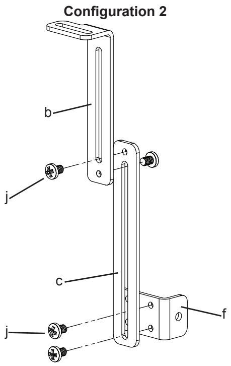
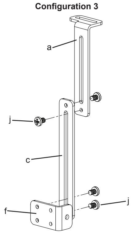
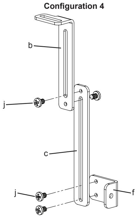
Configure the Speaker Attachments as shown in the Diagrams below. Tighten all Bolts with a Phillips screw driver. Repeat process for the second Speaker Attachment. The Extension assemblies can be adjusted vertically to adjust the vertical position of the speaker. The depth of the speaker can be adjusted by using the front set of holes or the back set of holes in the Speaker Bracket (f). The Upper Extensions can be adjusted using the slot in the top to adjust the depth of the speaker. Note: In rare occasions, the Lower Extensions may not be used. In this case, Speaker Bracket (f) may be attached directly to the Upper Extensions (a,b)
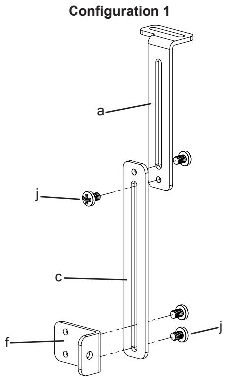
Step 6: Add Speaker Attachments to assembly
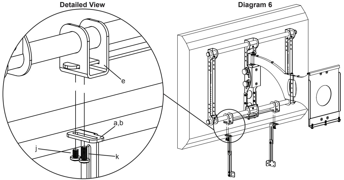
Thread a 1/4 - 20 x 3/8 Bolt (j) up through each Upper Extension (a,b) and into the Bar Bracket (e). Tighten to secure the Upper Extension. Thread a 1/4 - 20 x 5/8 Bolt (k) up through each of the Upper Extensions. Do not tighten the 1/4 - 20 x 5/8 Bolts at this time, you will tighten these so they bottom out into the Support Bar after the speaker is attached.
Note: For Speakers that have threaded inserts that are spaced between 1.75 inches and 15.5 inches use configuration 1. If the threaded inserts on the speaker are spaced wider than 15.5 inches, the tabs on the Speaker Brackets should face away from each other. In Diagram 6, Speaker Brackets shown facing toward each other.
Assembly Instructions for the VMDD and VMDD26 flat panel wall mounts.
Step 7: Remove mount from Wall Plate and remove lower Cross Tube from the mount assembly.
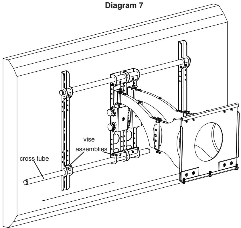
Remove the mount from the wall plate. Loosen the Allen Bolts in the lower four Vise Assemblies and remove the lower Cross Tube from the mount assembly. See Diagram 7 below.
Step 8: Add Axis Brackets
If the threaded inserts on your speaker are spaced between 1.5 inches and 5.7 inches, you do NOT need to use the Support Bar (g) for the installation.
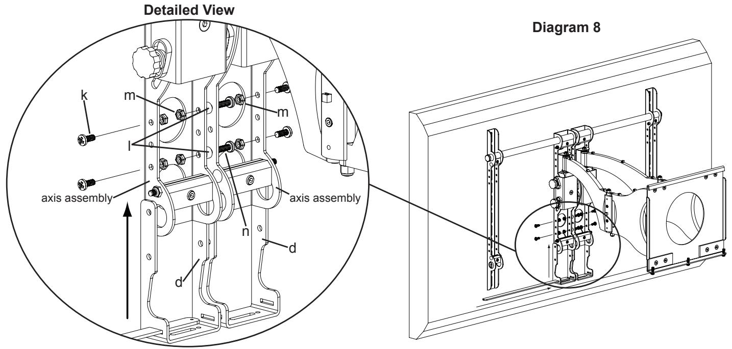
Position the Axis Bracket (d) so it fits the Axis Assembly on the mount. Insert 1/4 - 20 × 5/8 Bolt (k) through the outer side of the Axis Bracket, Axis Assembly, and into a 1/4 - 20 Nut (m). Insert a 1/4 - 20 × 1.5 Bolt (n) through the inner side of the Axis Bracket, a Spacer (l), the inner edge of the adjacent Axis Bracket. Thread it into a 1/4 - 20 Nut. Slide the Support Bar through the slots in each Axis Bracket until centered with the wall mount. See Diagram 8 below.
Step 9: Add Bar Brackets
Note: If the Support Bar was not installed in Step 8, only re-install the cross tube in this step.
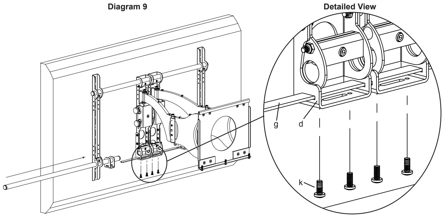
Slide the lower Cross Tube through the first Monitor Bracket, first Bar Bracket (e), both Axis Assemblies, a second Bar Bracket and through the second Monitor Bracket. Tighten all four Vise Assemblies to secure the Cross Tube once it is slid through the second Monitor Bracket. Thread each 1/4 - 20 × 5/8 Bolt (k) through each hole in the bottom of the Axis Bracket (d) until they bottom out against the Support Bar (g). See Diagram 9 below.
Step 10: Configure Speaker Attachments - Support Bar Not installed. If using Support Bar, see Step 5 for configuration.
Configure the Speaker Attachments as seen below. Tighten all Bolts with a Phillips screw driver. Repeat process for the second Speaker Attachment. See Diagrams below. The Extensions (a,b,c) can be adjusted vertically to adjust the vertical position of the speaker. The depth of the speaker can be adjusted by using the front set of holes or the back set of holes in the Speaker Bracket (f). The Upper Extensions can be adjusted using the slot in the top to adjust the depth of the speaker. Note: In rare occasions, the Lower Extensions may not be used.
Step 11: Add Speaker Attachments to assembly - Support Bar not installed
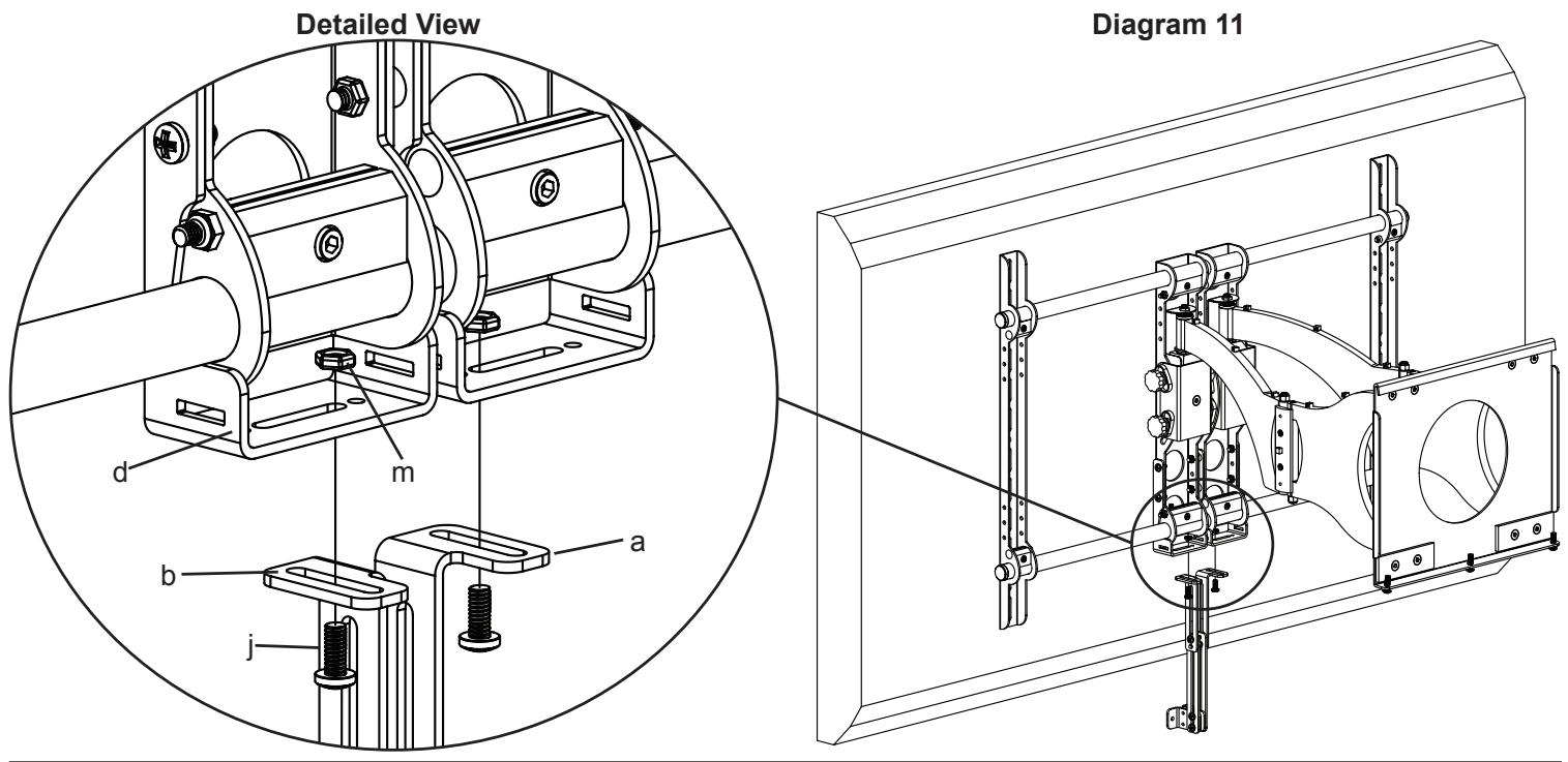
Thread a 1/4 - 20 x 3/8 Bolt (j) up through each Upper Extension (a,b) and through the slot in the Axis Bracket (d) and into a 1/4 - 20 Nut (m). Tighten so Upper Extension is secured. See Diagram 11 below.
Note: For Speakers that have threaded inserts that are spaced between 3.75 and 5.7 inches apart the tabs of the Speaker Brackets should face away from each other. If the threaded inserts on the speaker are spaced between 1.5 and 3.75 inches, the tabs on the Speaker Brackets should face each other. In example shown below, Speaker Brackets are configured for 3.75 to 5.7 inch threaded insert spacing.
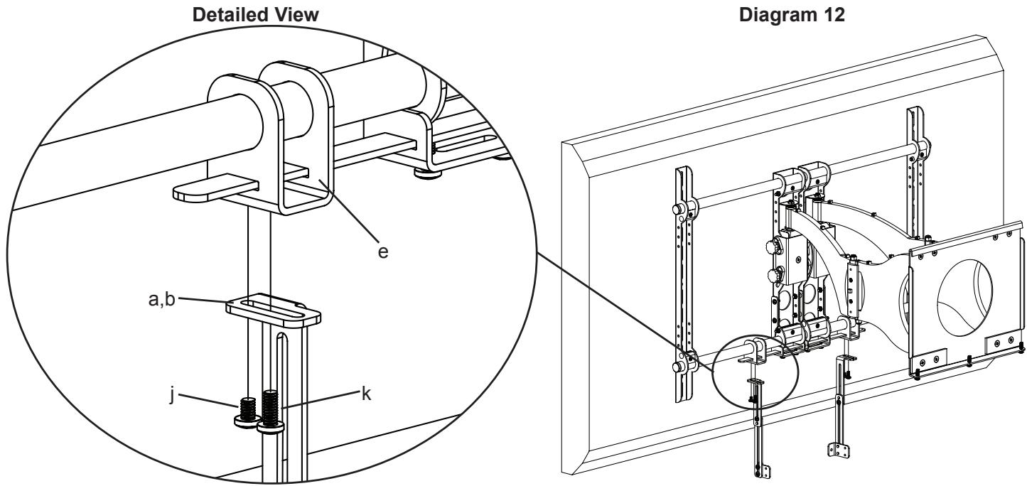
Step 12: Add Speaker Attachments to assembly - Support Bar installed
Thread a 1/4 - 20 x 3/8 Bolt (j) up through each Upper Extension (a,b) and into the Bar Bracket (e). Tighten so the Upper Extension is secured to the Bar Bracket. Thread a 1/4 - 20 x 5/8 Bolt (k) up through each of the Upper Extensions. Do not tighten the 1/4 - 20 x 5/8 Bolts at this time, you will tighten these so they bottom out against the Support Bar after the speaker is attached. See Diagram 12 below.
Note: For Speakers that have threaded inserts that are spaced between 5.7 and 15.5 inches wide, the tabs of the Speaker Brackets should face each other. If the threaded inserts on the speaker are spaced wider than 15.5 inches, the tabs on the Speaker Brackets should face away from each other. In Example shown below, Speaker Brackets are configured for the 5.7 to 15.5 range.
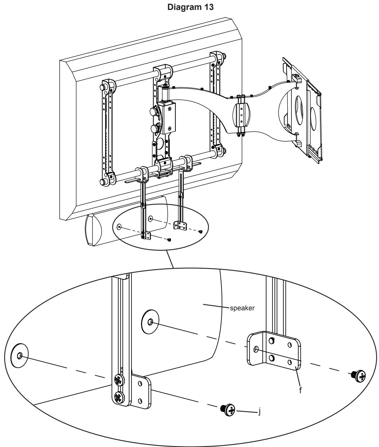
Step 13: Add center channel to VMCC1
Slide the Bar Brackets (e) until the Speaker Brackets (f) line up with the threaded inserts on the back of the speaker. Select the proper bolt for your center channel speaker by hand threading the M4 x 10 Bolt (h), M5 x 10 Bolt (i) or 1/4 - 20 × 3/8 Bolt (j) into the into the threaded inserts in the back of the speaker to determine which fits. Once you have selected the proper bolt, insert it through each of the Speaker Brackets and thread it into the center channel. Tighten each Bolt with a Phillips screw driver. See Diagram 13 below.
You can now center the speaker with the TV by sliding it left or right. Once it is positioned, tighten the 1/4 - 20 × 5/8 Bolt (k), installed in Step 6, until it bottoms out against the Support Bar.
To adjust the vertical placement of the speaker, loosen the 1/4 - 20 × 3/8 Bolts connecting the Upper and Lower Extension arms and reposition the arms until center channel is at desired position.
See Step 5 for depth adjustment of speaker.
SANUS SYSTEMS
BnHT M4 x 30 (i) -2 nT.
BnHT 1/4 - 20 x 3/8 (j) - 10 mT.
BnT 1/4 - 20 x 5/8 (k) - 10 mT.

IIaIb6a yctaHOBOUHna (1) - 2 IIIT.

Faika 1 / 4 - 20 m-8 nT.
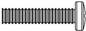
BnT 1/4 - 20 x 1500 (n) - 2 mT.