FMK056 - TV Mount SANUS - Free user manual and instructions
Find the device manual for free FMK056 SANUS in PDF.
User questions about FMK056 SANUS
0 question about this device. Answer the ones you know or ask your own.
Ask a new question about this device
Download the instructions for your TV Mount in PDF format for free! Find your manual FMK056 - SANUS and take your electronic device back in hand. On this page are published all the documents necessary for the use of your device. FMK056 by SANUS.
USER MANUAL FMK056 SANUS
F O U N D A T I O N S
FMK056
(6901-002058 <01>)
Sanus Systems
2221 Hwy 36 West
Saint Paul, MN 55113 USA
Customer Service
Americas: 800-359-5520 • 651-484-7988 • info@sanus.com
Europe, Middle East, and Africa: +31 40 2324700 • europe.sanus@milestone.com
Asia Pacific: 86 755 8996 9226·sanus.ap@milestone.com
sanus.com
©2010 Milestone AV Technologies, a Duchossois Group Company.
All rights reserved. Sanus is a division of Milestone.
All other brand names or marks are used for identification purposes and are trademarks of their respective owners.
| English Wood stud walls | Concrete/Concrete Block Walls | Choose an Option | CAUTION / WARNING | Do Not |
| Français Structure de murs en bois | Murs en béton coula ou en blocs de béton | Sélectionnez une option | ATTENTION/ AVERTISSEMENT! | Interdit |
| Deutsch Holzbalkenwände | Beton-/Betonsteinwände | Wählen Sie eine Option | VORSICHT / WARNING | Tun Sie Folgendes nicht |
| Espanol Paredes con montantes de madera | Paredes de Hormigón o de bloques de hormigón | Elija una opcción | PRECAUCION /iADVERTENCIA! | Prohibido |
| Portugues Paredes de pinto de madeira | Paredes de concreto/Paredes de bloco de concreto | Escolha uma opção | ATENÇão / AVISO! | Não |
| Nederlands Muren met houten balkenconstructie | Muren van beton/betonblokken | Kies een optie | VOORZICTHIG/WAARSCHUWING | Niet |
| Italiano Pareti con montanti in legno | Pareti in calcestruzzo/blocchi di calcestruzzo | Scegliere un'opzione | PRECAUZIONE/AVVERTENZA | Divieto |
| Étalienuá Toíxoi με ξύlvους opôθοτάτες | Toíxoi anó ακυρόδεμα/ τοιεντόλθους | Επλέχτε μία επλογή | ΠΡΟΞOXH/ ΠΡOEΙΔΟΤΟΙΗΣH | Mην |
| Norsk Vegger med trestendere | Betongvegger/vegger av betongblokker | Velg et alternatively | FORSIKTIG/ADVARSEL | Forbudt |
| Dansk Vægge med trædyveler | Beton / betonblokkvægge | Vælg en mulighed | FORSIGTIG/ADVARSEL | Advarsel |
| Svenska Väggar med tråreglar | Betong/Betongvagg | Välj att entativ | FÖRSIKTIGHT/VARNING | Gör inte |
| РусKenni Стета с древаньим karpakom | Стеты ИЗ 6teToNa/6teToHьх 6nokOB | Выберпес вариANT | ПРЕДУПЕЖДЕНЕ/ ПРЕДУПЕЖДЕНЕ | Запрается |
| polski Drewniane sciany szkieletowe | Ściany z betonu lub pustáków betonowych | Wybrać opcję | UWAGA / OSTRZEŽENIE | Nie naleźty: |
| Česky Zdi s dřevěnými výztuhami | Zdi z betonu/panelú | Vyberte Jednu možnost | POZOR / VAROVÁNI | Nedělat |
| Türkce Ahşap Profill Duvarlar | Beton/Beton Blok Duvarlar | Seçeneklerden Birini Belirleyin | DİKKAT / UYARI | Yapilmaması Gerekenler |
| 日本語 木製sstad壁 | CONKLERA-10/CONKLERA- 10 flukschlag | 才浦�広の選択 | 注意/警告 | 禁止事項 |
| 中文 木牆柱墻壁 | 混凝土/混凝土砌块墙 | 选择一个选项 | 小心/警告 | 请勿 |
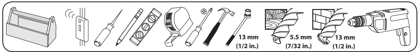
| English Tools required | WARNING: This product contains small items that could be a choking hazard. | Troubleshooting and Maintenance | Repeat Step | Heavy! Assistance Required. |
| Français Outils nécessaires | Ce produit contient de petites pieces qui peuvent représentier un risque d'étouffement. | Dépannage et maintenance | Répétez l'été | TRÉS LOURD! Cette étape requiert deux personnes. |
| Deutsch Benöttigte Werkzeuge | Dieses Produkt enthalt kleine Teile, die zum Erstickungstod führen können. | Fehlerbehebung und Wartung | Wiederholen Sie den Schritt | VORSICHT, SCHWER! Bei diesen Schritt werden Sie Hilfe benötigen. |
| Espanol Herramrientas necessarias | Este produit contiene piezas preocupas que, si fuesen tragadas, podr汕 producir asfixia. | Resolución de problemas yremenitimiento | Repita este paso | jPESADO! Necessitará ayuda para realizar esta operación. |
| Portugues Ferramentas necessarias | Este produits contém它们ospequenos queedomofecreriscode sufocamento. | Solução de problema emanutenção | Repita a etapa | PESADO! Necessitará de ajudaesta etapa. |
| Nederlands Benodigcdereedschap | Dit product bevatkleine onderdelendie stikkingsgveaar kuren opleveren. | Probleemoplossing enunderhoud | Herhaal stap | ZWAAR! Voor het uitvoeren van deze stap is assistentie vereist. |
| Italiano Strumenti richiesti | Questo prodotto comprehende elementi di piccole dimensioniche potrebbero causare il soffocamento. | Risoluzione dei problemi e manutenzione | Ripetere l'operazione | PESANTE! Per QUESTa operazione, si avrà bisogno di aiuto. |
| Ельникá Anatroúmeva εργαleía | To prooióu autó περιλαμβάνεi μκráa αντικίμενα που μιρορεi va anotetλέσουν κινδυνο πυγμο. | Аντιμετώπηη προβλημάτων κai Συντήροη | Enavaλαβετε to βήμα | BAPY! Θα χρειαστείτε Βοήθεια σ' αυτο το βήμα. |
| Norsk Nødvendig verktøy | Dette produktet ineholder smalementer som kan utgjore kvelefare. | Feilsøkning og vedlighold | Gjenta trinn | TUNG! Du vil trenga hjelp tildeen operasjorden. |
| Dansk Redskaber, der skal bruges | Dette produkt ineholder sma dele, som kan forarssage kvælning, hvis de bliver sleptg. | Fejlfinding ogVedligeholdelse | Gentag trin | TUNG! Du skal bruge hjælp, när du udfører dette trin. |
| Svenska Verktgy som behövs | Den härprodukten innehäller sma délar som kan utgóra kväningsrisik. | Felsökning och underhäll | Upprepaa steg | TUNG! DuCOMMBERATT behöva hjäpl under det här steget. |
| Russkien Heobxodimbile Инструменты | Виаделем с这笔 мелкиме детали, которье могут сстby пчунно удунеця рп поладамы в дьхатьньпутп. | Усталенье Невсравносту и облужване | Повtorпь.DeястVEN | БОЛьшой BEC!Прь Великовенци данно onepazсь вам поадобитсяnomоць. |
| polski Wymagane narędzia | Produkt zwiera male elementy, kto're moga grozić zakrztszeniem. | Rozwiązywanie problemów i konserwacja | Powtórzć krok | CIEŽKIE! W tej czynnosci potrzebnja三点茲 potocmoc drugiej osoby. |
| Česky Požadované nastroje | Tento vyrobek obsahujeme malé součástky, které hrózi rizikem zaduzeni. | Rešeni problemù a ûdržba | Opakovat krok | TěŽKIE! K tomuto kroku budete potefbovat pomocnika. |
| Türke Gereken Aletler | Bu urün, boğulma tehlikesine neden olabilecek küçuk parçalar icermetektdir. | Sorum Giderme ve Bakim | Adimi Tekrarlayin | AGIR MALZEME! Bu aşamada yardima İhtiyacıniz vardir. |
| 日本語 必要的スル | 本製品のはは小さい部品が付属ており、窒息の危険性のはんだ。 | トラフローデイングとメntテANNUS | 手順の縄返し | 重量お願い! 这の操作は2人で行動て+kだき。 |
| 中文 需要的工具 | 此产品包含可能带来窒息危险的小组件。 | 故障排除与维护 | 重复步骤 | 支架臂很重! 该步骤需要协助。 |
English
IMPORTANT SAFETY INSTRUCTIONS - SAVE THESE INSTRUCTIONS - PLEASE READ ENTIRE MANUAL BEFORE USING THIS PRODUCT
For best results, reference both the text and illustrations when using this manual. Cut along the dashed lines to match your language with the illustrations.
English Text Pages 1-20
Français
INFORMATIONS IMPORTANTES CONCERNANT LA SECURITE - CONSERVEZ CES INSTRUCTIONS - VEUILLEZ LIRE ATTENTIVEMENT LE MANUEL AVANT D'UTILISER CE PRODUIT
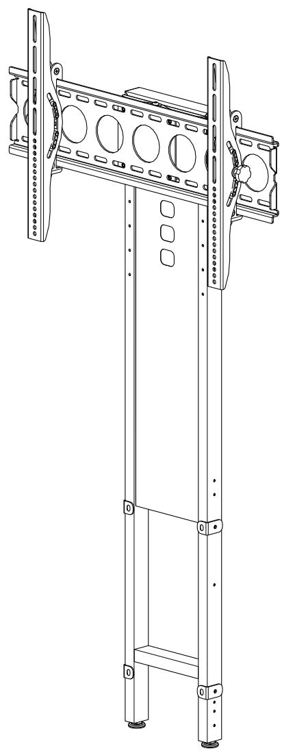
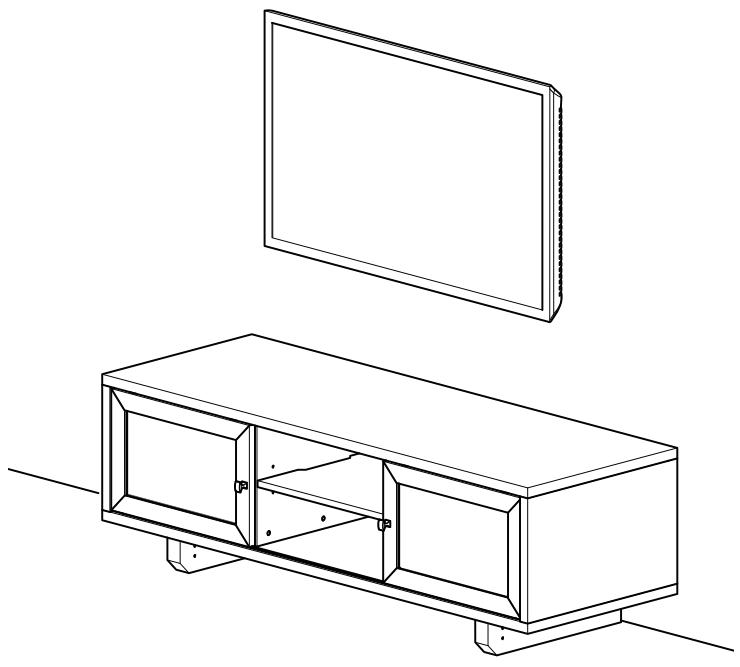
Thank you for choosing the FMK056 pillar kit. The FMK056 allows you to mount your TV to the wall or to the pillar mounted on select Sanus furniture.
For wall mounting, see steps 1, 7, and 8.
For pillar mounting, see steps 1-6 and 8.
Specifications
Weight capacity: 59kg (130 lbs)
Swivel: ± 15^ (pillar mounting option only)
Tilt: ±12°

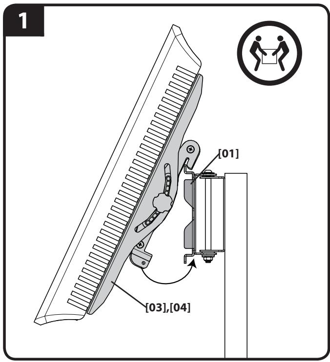
TV MOUNTED TO WALL STEPS 1, 7, AND 8
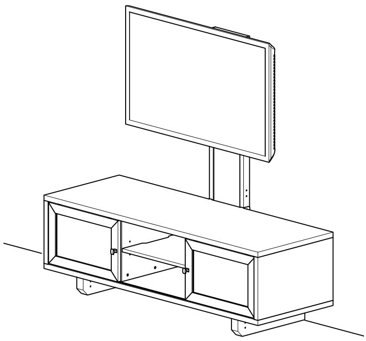
TV MOUNTED TO PILLAR STEPS 1-6 AND 8
CAUTION:
CAUTION: Avoid potential personal injuries and property damage!
- Do not use this product for any purpose not explicitly specified by manufacturer.
The wall must be capable of supporting five times the weight of the monitor and mount combined.
This product is not designed for use in metal stud walls!
If you do not understand these instructions, or have doubts about the safety of the installation, assembly or use of this product, contact manufacturer Customer Service or call a qualified contractor.
Manufacturer is not responsible for damage or injury caused by incorrect assembly or use.
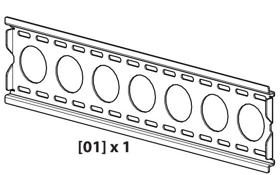
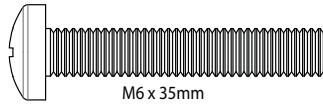
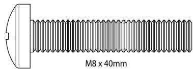
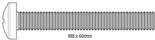
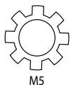
Supplied Parts and Hardware
Before starting assembly, verify all parts are included and undamaged. If any parts are missing or damaged, do not return the damaged item to your dealer; contact Customer Service. Never use damaged parts!
NOTE: Depending on your configuration needs, not all hardware provided will be used.
[03] x 1
[04] x 1
[05] x 1
[06] x 4
[07] x 2
[08] x 8
M5×16mm
[09] x 4
[10] x 4
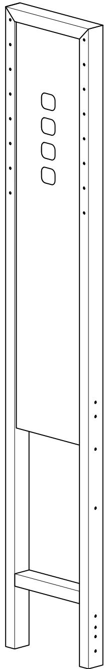
[02] x 1
[11] x 4
[12] x 4
[13] x 4

[14]:
[15] x 4
[16] x 4
[17] x 4
[18] x 4
[19] x 4
[20] x 4

[21] x 4
[22] x 4
[23] x 4
[24] x 4
[25] x 8
[26] x 4
[27] x 4
[28] x 4
5/16 in.
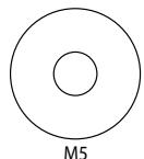
[30] x 6
[31] x 6
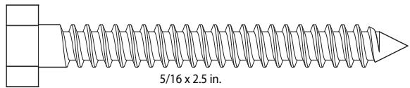
[29] x 6
[32] x 2
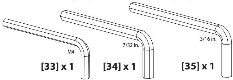
[33] x 1
[34] x 1
[35] x 1
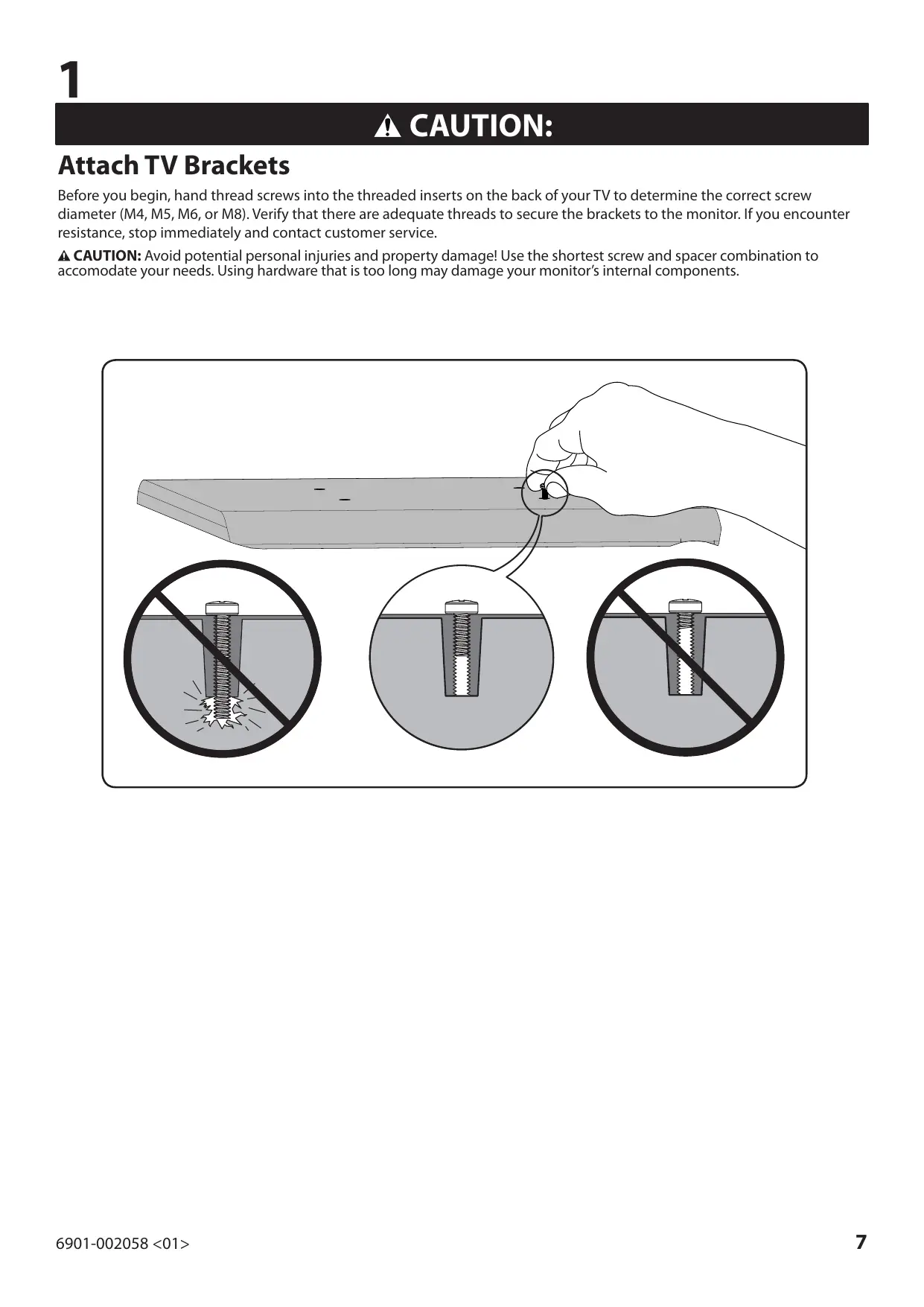
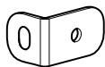
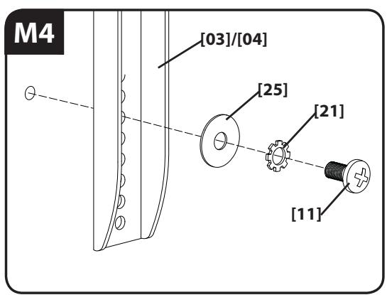
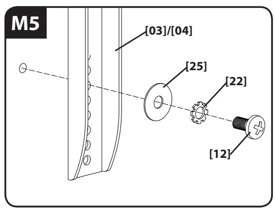
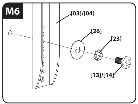
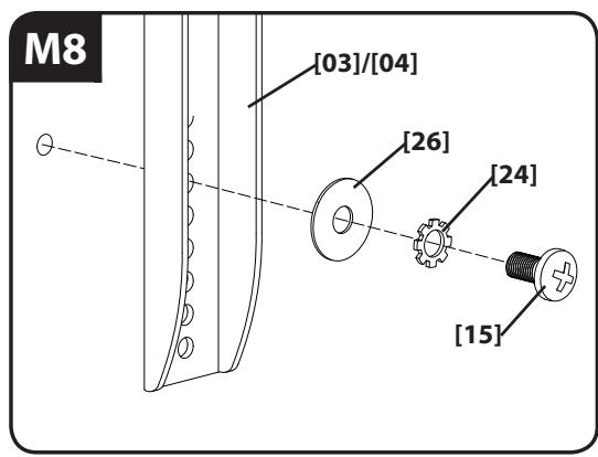
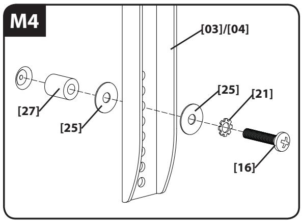
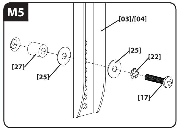
Attach TV Brackets
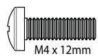
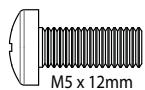
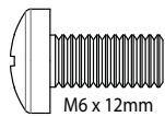
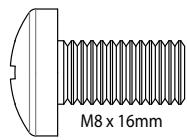
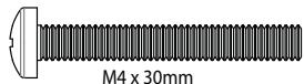
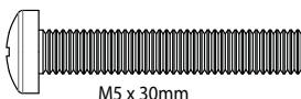
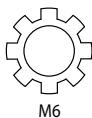
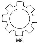
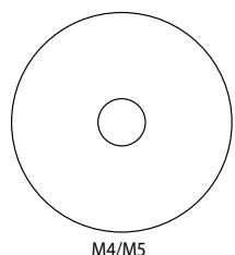
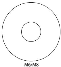
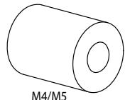
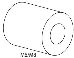
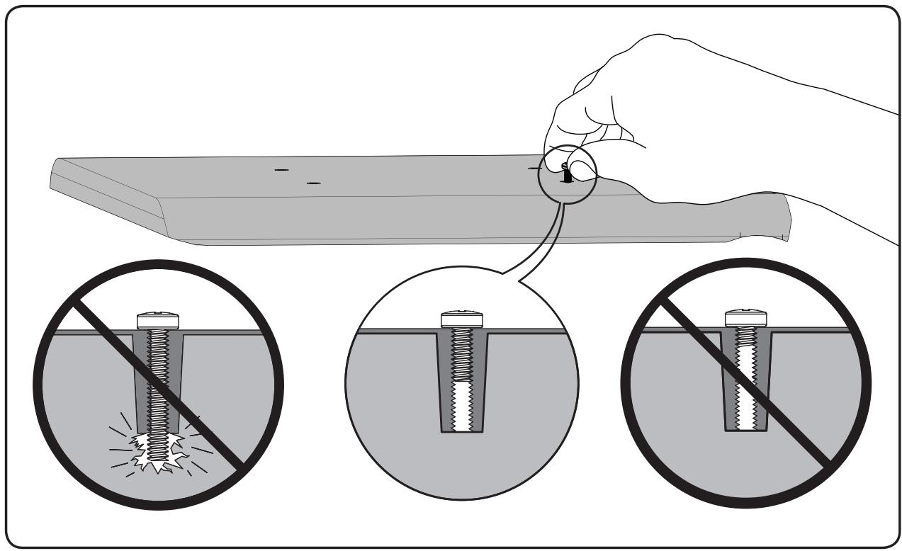
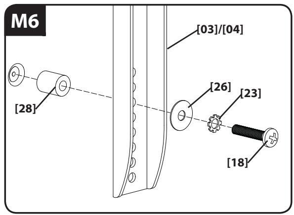
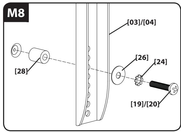
Before you begin, hand thread screws into the threaded inserts on the back of your TV to determine the correct screw diameter (M4, M5, M6, or M8). Verify that there are adequate threads to secure the brackets to the monitor. If you encounter resistance, stop immediately and contact customer service.
CAUTION: Avoid potential personal injuries and property damage! Use the shortest screw and spacer combination to accommodate your needs. Using hardware that is too long may damage your monitor's internal components.
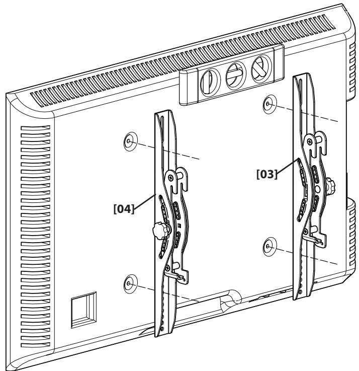
For TVs with a flat/unobstructed back. Ensure that the brackets are level on the back of the TV. If you need extra space to accommodate cables, recesses, or protrusions, see an installation option (1-2) that uses spacers.
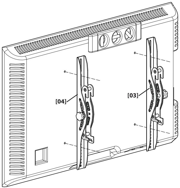
For TVs with an irregular/obstructed back or to accommodate cables. Ensure that the brackets are level on the back of the TV. Standard configurations are shown. For special applications, or if you are uncertain about your hardware selection, contact Customer Service.
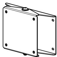
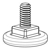
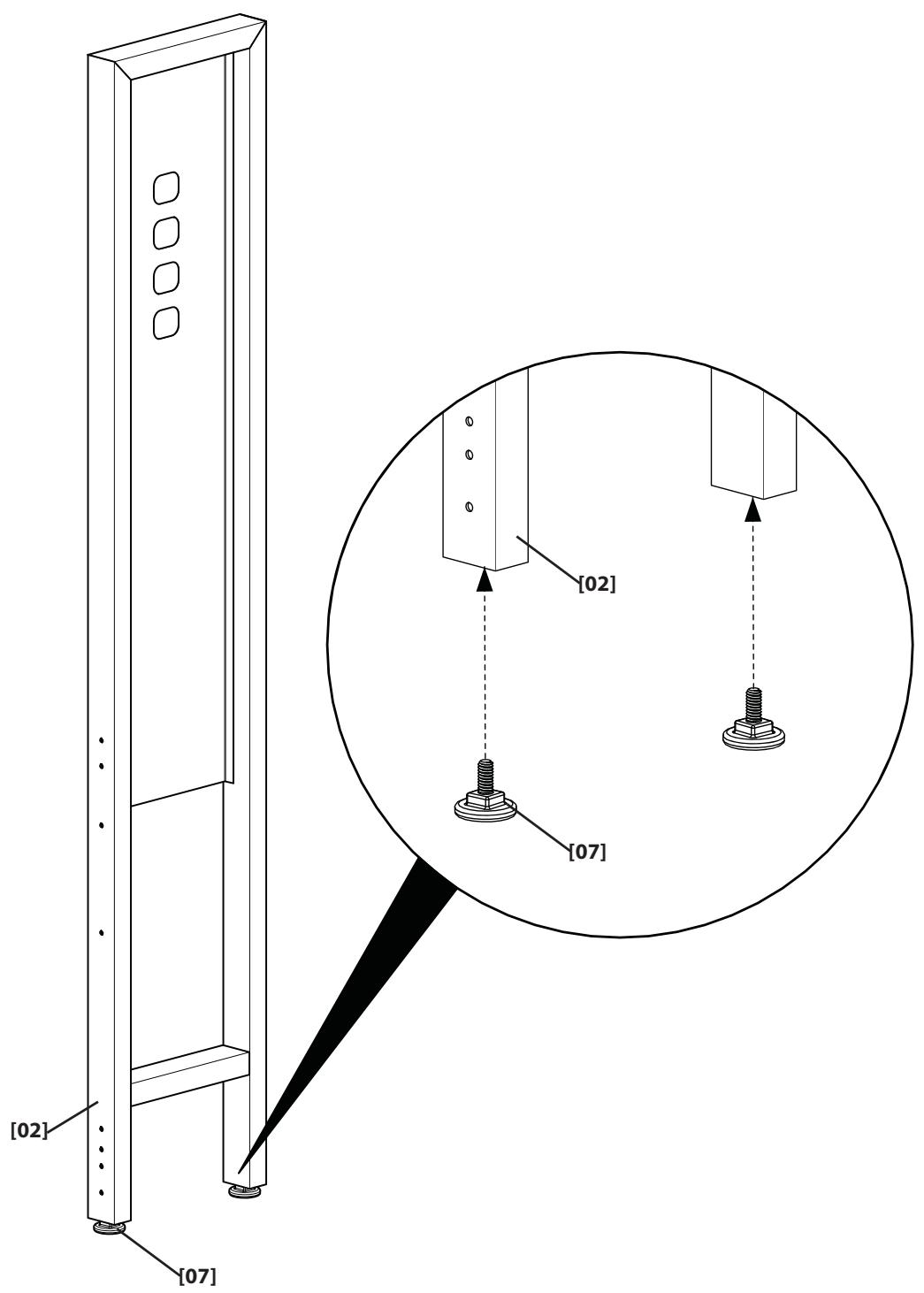
Attach Feet to Pillar
NOTE: This step is for mounting the TV to the pillar only. If you are mounting your TV to the wall go to step 7.
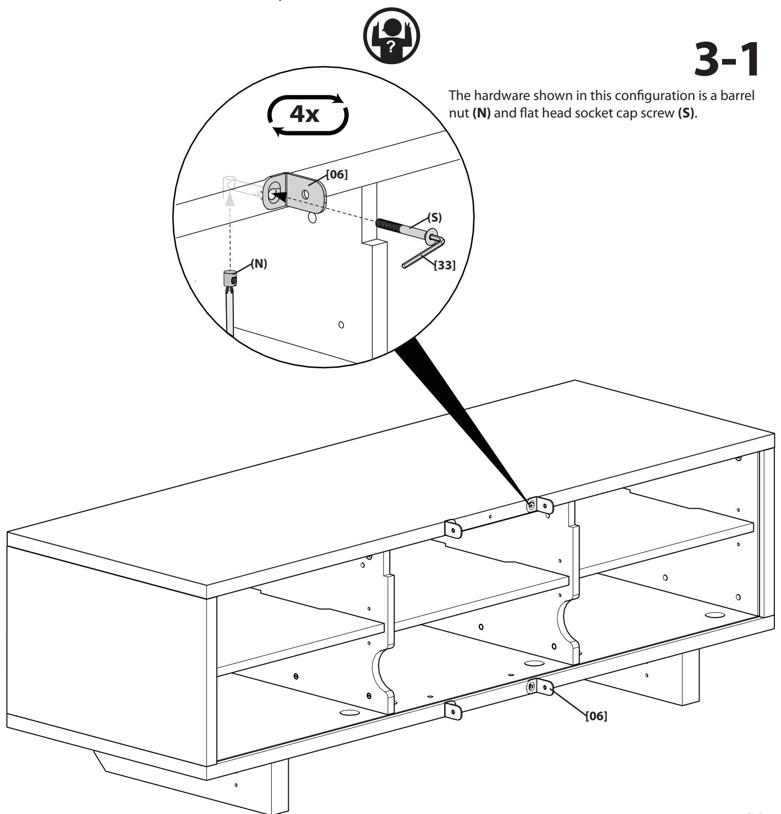
Attach Pillar Brackets to Furniture
NOTE: The hardware needed to attach the pillar kit brackets [06] is included with your select Sanus furniture. If your furniture comes with:
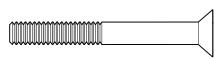
A barrel nut and flat head socket cap screw

see 3-1.
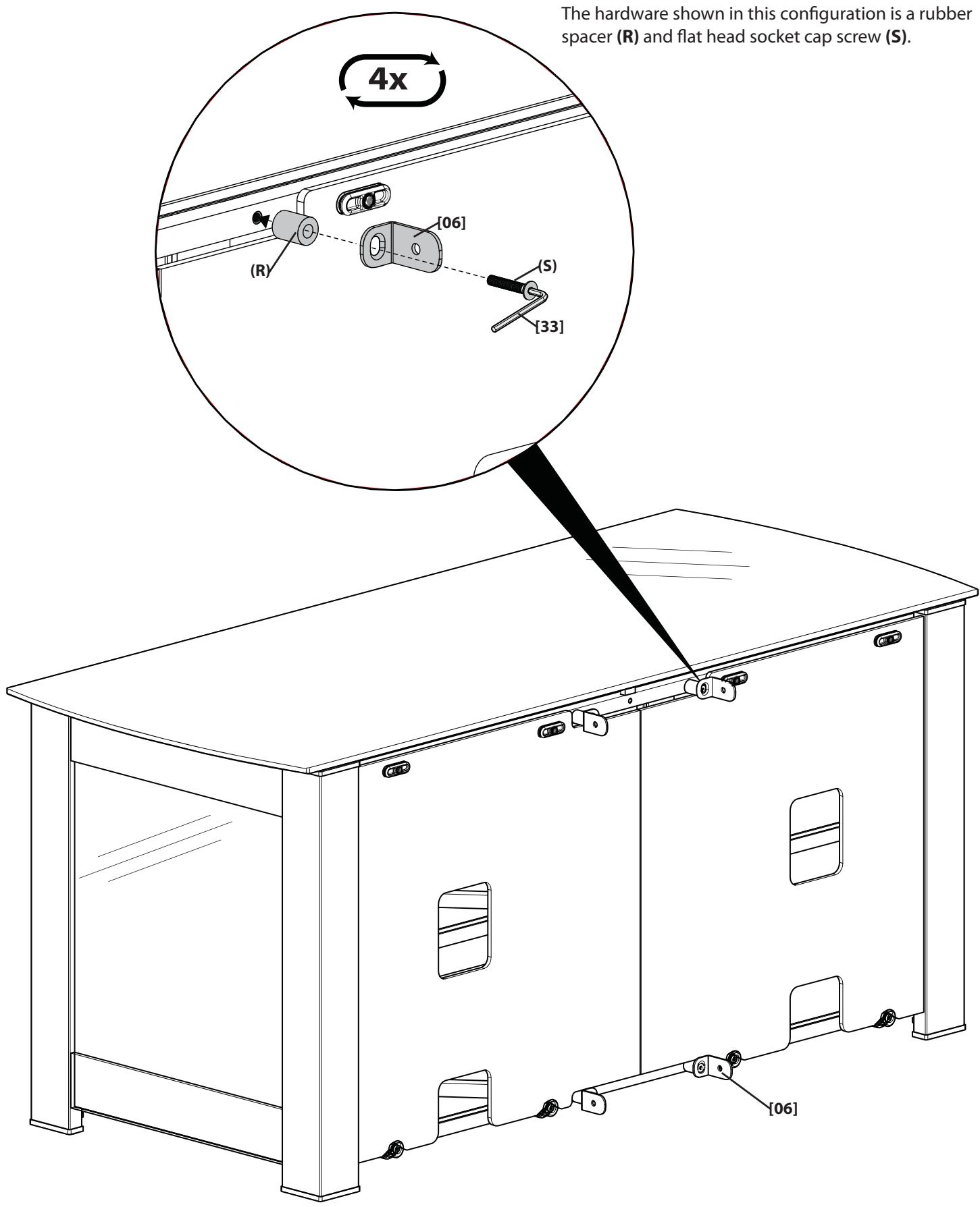
A rubber spacer and flat head socket cap screw

see 3-2.
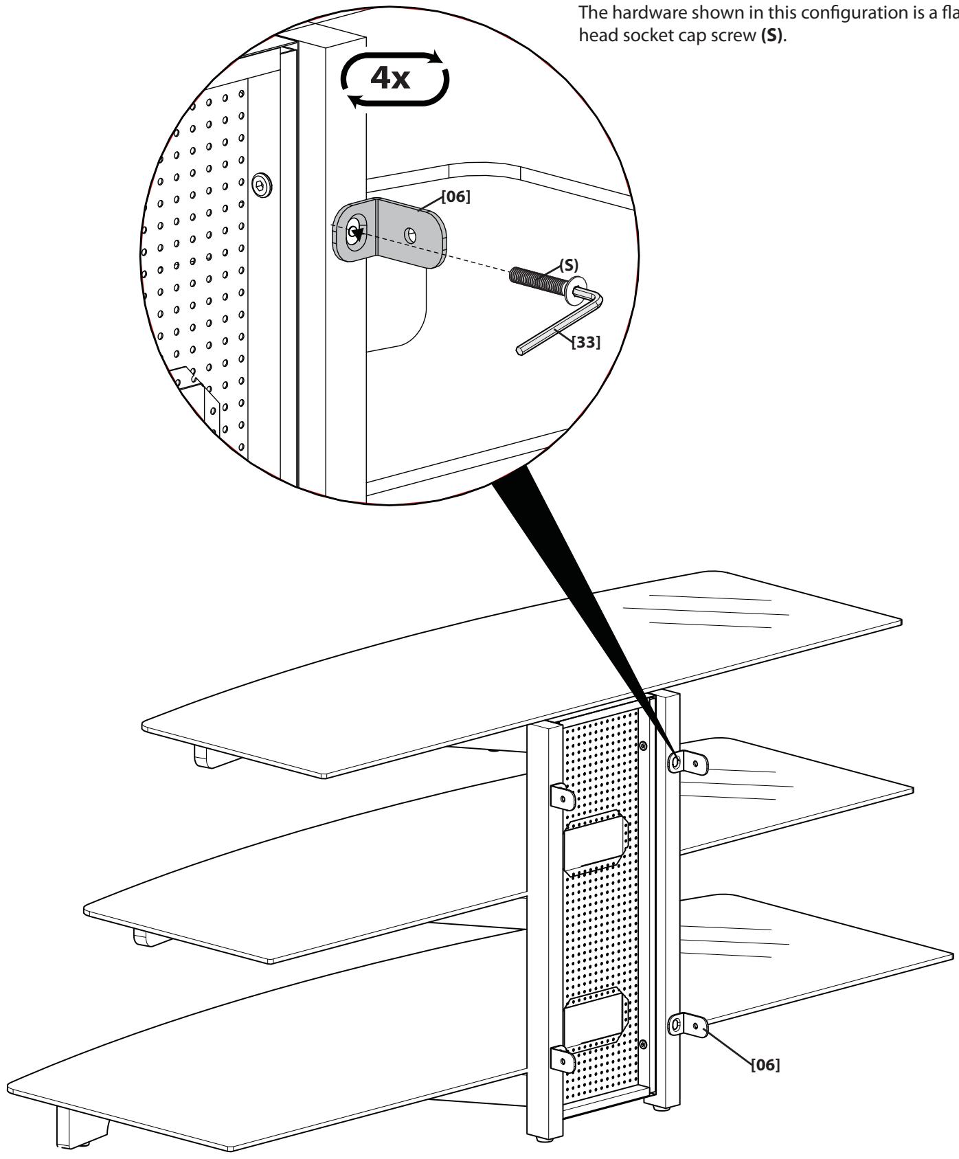
A flat head socket cap screw see 3-3.
The hardware shown in this configuration is a rubber spacer (R) and flat head socket cap screw (S).
The hardware shown in this configuration is a flat head socket cap screw (S).
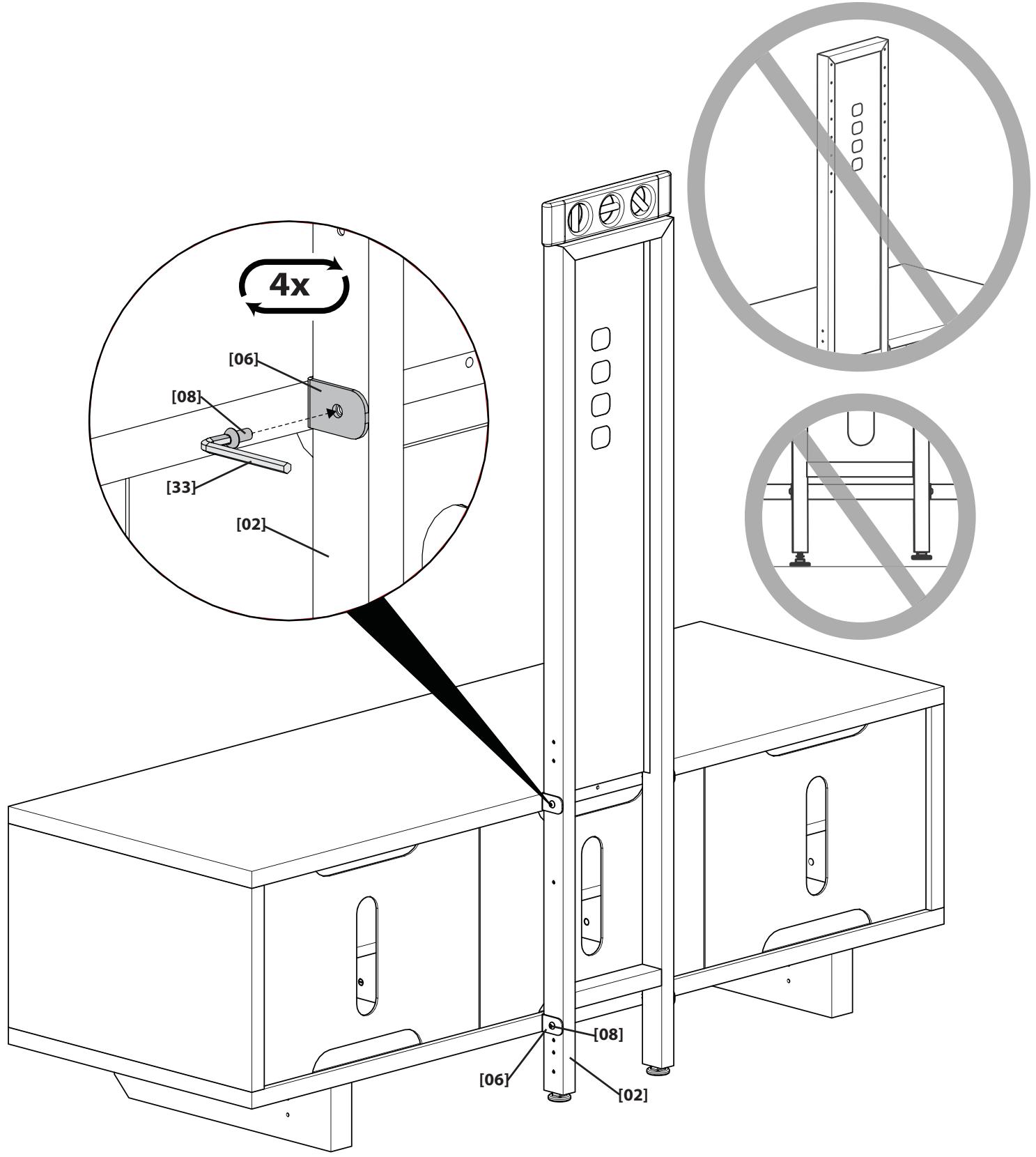
Attach Pillar to Brackets
Attach the pillar [02] to the brackets [06] making sure the top mounting holes face the front of the furniture. Ensure that the feet [07] are firmly on the floor and level.
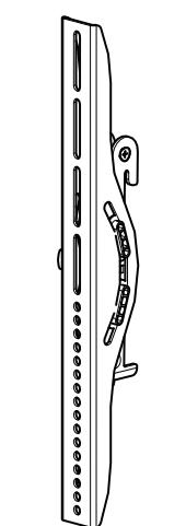
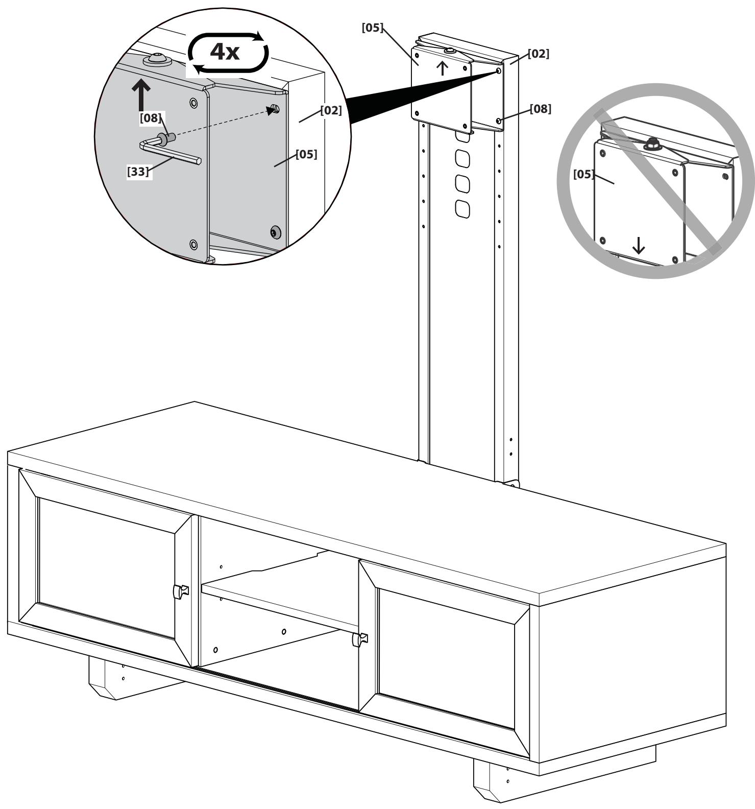
Attach Pivot Head to Pillar
Attach the pivot head [05] to the pillar [02].
NOTE: The pivot head can be installed to any of the mounting holes on the pillar. Where you install the pivot head depends on the size of your TV and how much space you want between the bottom of the TV and the top of the furniture. Ensure all four screws [08] are securely fastened.
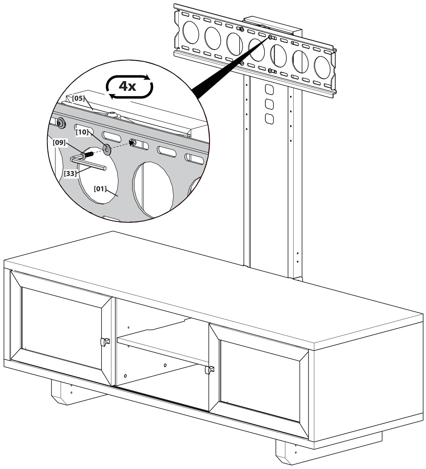
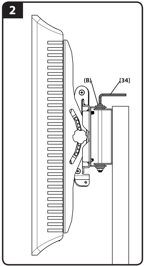
Attach Wall Plate to Pillar
CAUTION:
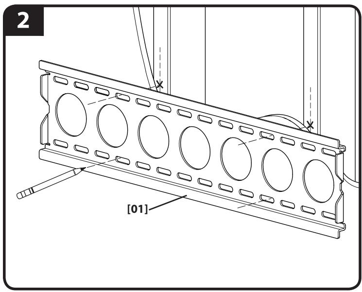
Attach Wall Plate to Wall
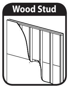
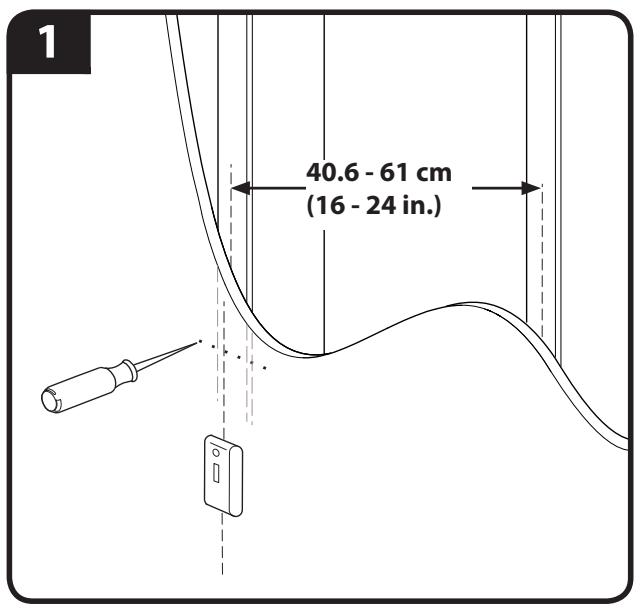
Wood Stud Mounting
- Locate studs. Verify the center of the stud with an awl or thin nail or use an edge to edge stud finder.
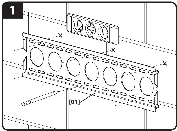
- Level the wall plate [01] and mark the hole locations.
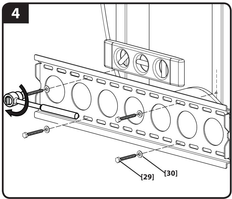
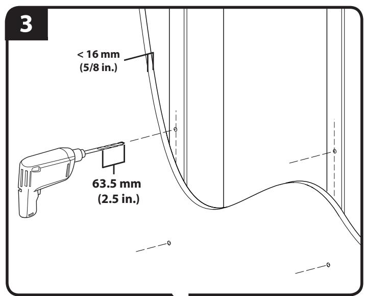
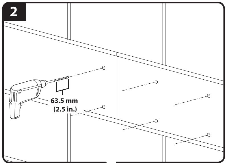
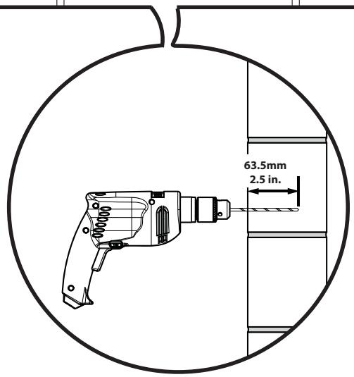
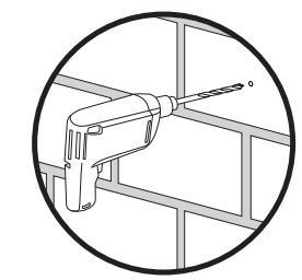
- Drill pilot holes as illustrated.
- Tighten the lag bolts [29] only until the washers [30] are pulled firmly against the wall plate [01].
CAUTION: Improper use could reduce the holding power of the lag bolt. To avoid potential injuries or property damage:
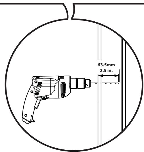
- Pilot holes MUST be drilled to a depth of 63.5 ~mm (2.5 in.), using a 5.5 ~mm (7/32 in.) diameter drill bit.
Do not over-tighten the lag bolts [29].
Any material covering the wall must not exceed 16mm (5/8 in.).
CAUTION:
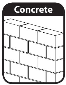
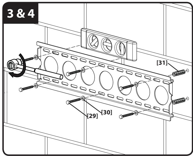
Solid Concrete and Concrete Block Mounting
- Level wall plate [01] and mark the hole locations.
- Drill pilot holes as illustrated.
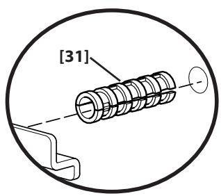
- Insert lag bolt anchors [31] and then insert lag bolts [29].
- Tighten the lag bolts [29] only until the washers [30] are pulled firmly against the wall plate [01].
CAUTION: Improper use could reduce the holding power of the lag bolt. To avoid potential injuries or property damage:
Mount wall plate directly onto the concrete surface.
Pilot holes MUST be drilled to a depth of 63.5mm (2.5 in.), using a 13mm (1/2 in.) diameter drill bit.
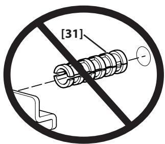
- Be sure the anchors [31] seat flush with the concrete surface.
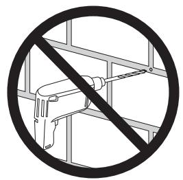
- Never drill into the mortar between blocks.
Do not over-tighten the lag bolts [29].

CAUTION:
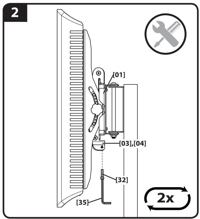
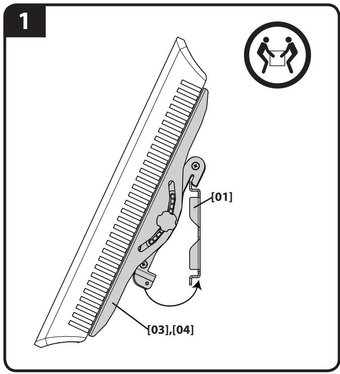
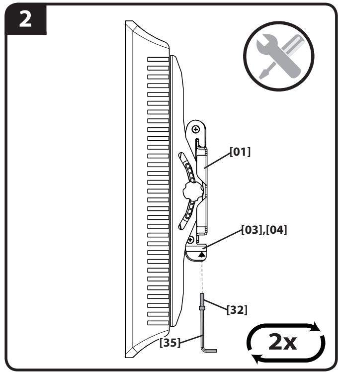
- Attach TV to wall plate [01].
- Install safety bolts [32].
CAUTION: Avoid potential personal injuries or property damage! Be sure to install the safety bolts [32]. Periodic tightening may be required.
TV MOUNTED TO PILLAR

TV MOUNTED TO WALL
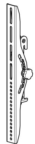
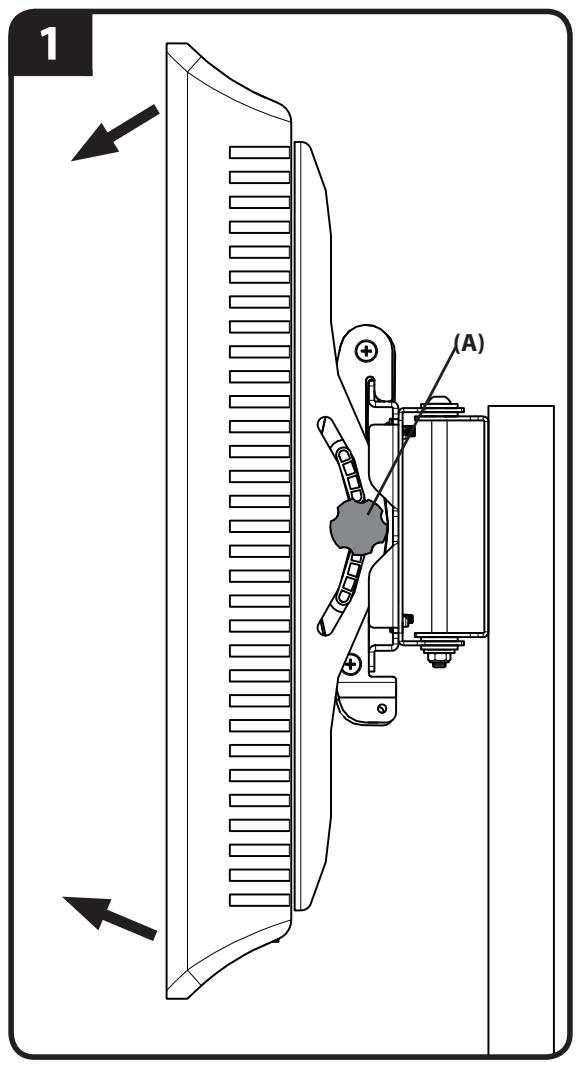
- Adjust tilt tension (A).
- Adjust swivel tension (B).
ATTENTION:
INFORMATIONS IMPORTANTES CONCERNANT LA SECURITE - CONSERVEZ CES INSTRUCTIONS - VEUILLEZ LIRE ATTENTIVEMENT LE MANUEL AVANT D'UTILISER CE PRODUIT
NOTA: Anything passed as a passo.
YcTaHOBtTe TeneBn3NoHHbIe KpOnHTeiHbI
Ipeed nauJOM yCTaHOBKn BCTaBbTe BVNTbI B OTBepCTnHa 3aJHei NaHei TeLEBn3Opa Iry OnPeJeHEny COOTBeTCTByUoJero DnAmEtpa BVHTa (M4, M5, M6 nn M8). PpOBepbTe, DoCTaTOUHO nn dInHbI pe3b6bl, YTO6bl pNkPeINtB KPOHHTeHbI K MOHTOpY. Ecnn BVHTb 3aTgRNaIOrTa IILOXO, HEmeJLeHNO pKeKpATte UCTaHOBky n O6paTITecb B OTdEL TexHnuecko nOndepxkn.
PNEyPExHHeNc: Co6nlaTe npabina 6e3oNaChocTn, YTO6bl npedeTbpaTb BO3MOxHbIe TpaMbI INOBpeXHeHne IMUeCTBa! NcnoJIb3yIte COyEtAHne BVHTa I pOKnAaKn HAnMeHbSeI POxOJaIe dInHb.IcNoB3OBAHne CIniKOM dInHHoro KpeJexa MOKeT npINBeCTN KIOBpeXDeHIO BHyTpEHnx KOMNOHETOB MOHITopa.
1-1 cm. nllnoctpaunio ha ctp.8
IJIyTeBn3OpOB C nIIOCKo/6e3 BbCTynOB 3aHNe IaHEnbU. Y6eINTEcB TOM, YTO KPOHtEHNb Ha 3aHNe IaHEn MoHHTopa yCTaHOBHeB IO yPOBnO. EcII trpe6yETcdoONHITelbHoe npocTpaHCTBO, YTObI yLOXkTB Ka6eJIb, NODOrHaTb yToPnEHHbIe INIi BbInyKlbIe NOBepxHOCTN, CM. OIN H3 BapnaHTOB yCTaHOBKN (1-2) C nICNoJIb3OBAHnEM BTyNOK.
1-2 cm. nllnoctpaunio ha ctp.9
IyTeBn3OpOB C HepOBHoi/C BbIcTynamn 3aDnei naHeIbIo. Y6eIITecb B TOM, UTo KpoHsTeHbI Ha 3aDnei naHeII MOHITopa yCTaHOBJIbI IO npOBoHIO.
Ha pncyHke nok3aHbI cTaNdapThbIe KOHnpyaun. IJra noluyehn HnOopMaun O HeCTaNdapTHbIX KOHnpyaunx yToUHeHn Bbl6opa npncnco6JeHn 6oBpaNTecb B OTen TexHnueckon PndepkKn.
2 cm. mllioctpaunio ha ctp. 10
Ppncoeunene HOxK K cToiKe
PIMMEYAHNE.3OTIARHyJKeTOLBkoPnUyCTaHOBKeTeJeBn3OpaHa CToIKe.EcNBIyUyCTaHABINBaTe TeJeBn3Op Ha CTeH,TO npEpeiDITE K 1ary 7.
3 cm. mllioctpaunio Ha ctp. 11
Kpenenne ctoeHbIX KpOnHTeHOB K Me6eI
PIMMEAHHE. INHCTpymEnT, Heo6xOaMbI dIy npincoeINHeNc TcOeHbIX KPOHtEiHOB [06], pInpnaTaEcTc K Bbl6paHHO Me6enSanas.
EcnB CocTaB Me6eIbHOrO KOMnJIeKtA BXoJrT:
LINHINDPINueckraIaKaN BINTC pIOCKoRTOJOBKOc yrIy6neHmE IOKIOU. Cm.3-1.
Pe3nHOBA BtUka N BHT C ploCKO rOLOBKO C yrgy6neHnem eo KIOU. Cm. 3-2.
BnT C nIOCKo rOIOBko C yrgy6JeHneM eoKJIouc. Cm. 3-3.
3-1 cm. nllnoctpaunio ha ctp. 11
Aayagi Sutuna Monte Edin
Milestone AV Technologies and its affiliated corporations and subsidiaries (collectively, "Milestone"), intend to make this manual accurate and complete. However, Milestone makes no claim that the information contained herein covers all details, conditions, or variations. Nor does it provide for every possible contingency in connection with the installation or use of this product. The information contained in this document is subject to change without notice or obligation of any kind. Milestone makes no representation of warranty, expressed or implied, regarding the information contained herein. Milestone assumes no responsibility for accuracy, completeness or sufficiency of the information contained in this document.