
YCS50H - Guitar amplifier TRAYNOR - Free user manual and instructions
Find the device manual for free YCS50H TRAYNOR in PDF.
User questions about YCS50H TRAYNOR
0 question about this device. Answer the ones you know or ask your own.
Ask a new question about this device
Download the instructions for your Guitar amplifier in PDF format for free! Find your manual YCS50H - TRAYNOR and take your electronic device back in hand. On this page are published all the documents necessary for the use of your device. YCS50H by TRAYNOR.
USER MANUAL YCS50H TRAYNOR
A L L - T U B E G U I T A R A M P L I F I E R
IMPORTANT SAFETY INSTRUCTIONS

This lightning flash with arrowhead symbol, within an equilateral triangle, is intended to alert the user to the presence of uninsulated "dangerous voltage" within the product's enclosure
that may be of sufficient magnitude to constitute a risk of electric shock to persons.
The exclamation point within an equilateral triangle is intended to alert the user to the presence of important operating and maintenance (servicing) instructions in the ccompanying the appliance.
Instructions pertaining to a risk of fire, electric shock, or injury to a person
CAUTION: TO REDUCE THE RISK OF ELECTRIC SHOCK,DO NOT REMOVE COVER (OR BACK).
NO USER SERVICEABLE PARTS INSIDE.
REFER SERVICING TO QUALIFIED SERVICE PERSONNEL.
Read Instructions: The Owner's Manual should be read and understood before operation of your unit. Please, save these instructions for future reference and heed all warnings.
Clean only with dry cloth.
Packaging: Keep the box and packaging materials, in case the unit needs to be returned for service.
Warning: To reduce the risk or fire or electric shock, do not expose this apparatus to rain or moisture. Do not use this apparatus near water!
Warning: When using electric products, basic precautions should always be followed, including the following:
Power Sources
Your unit should be connected to a power source only of the voltage specified in the owners manual or as marked on the unit. This unit has a polarized plug. Do not use with an extension cord or receptacle unless the plug can be fully inserted. Precautions should be taken so that the grounding scheme on the unit is not defeated.
Hazards
Do not place this product on an unstable cart, stand, tripod, bracket or table. The product may fall, causing serious personal injury and serious damage to the product. Use only with cart, stand, tripod, bracket, or table recommended by the manufacturer or sold with the product. Follow the manufacturer's instructions when installing the product and use mounting accessories recommended by the manufacturer.
The apparatus should not be exposed to dripping or splashing water; no objects filled with liquids should be placed on the apparatus.
Terminals marked with the "lightning bolt" are hazardous live; the external wiring connected to these terminals require installation by an instructed person or the use of ready made leads or cords.
Ensure that proper ventilation is provided around the appliance. Do not install near any heat sources such as radiators, heat registers, stoves, or other apparatus (including amplifiers) that produce heat.
No naked flame sources, such as lighted candles, should be placed on the apparatus.
Power Cord
Do not defeat the safety purpose of the polarized or grounding-type plug. A polarized plug has two blades with one wider than the other. A grounding type plug has two blades and a third grounding prong. The wide blade or the third prong are provided for your safety. If the provided plug does not fit into your outlet, consult an electrician for replacement of the obsolete outlet. The AC supply cord should be routed so that it is unlikely that it will be damaged. If the AC supply cord is damaged DO NOT OPERATE THE UNIT.
Unplug this apparatus during lightning storms or when unused for long periods of time.
Service
The unit should be serviced only by qualified service personnel.
SUIVEZ TOUTES LES INSTRUCTIONS
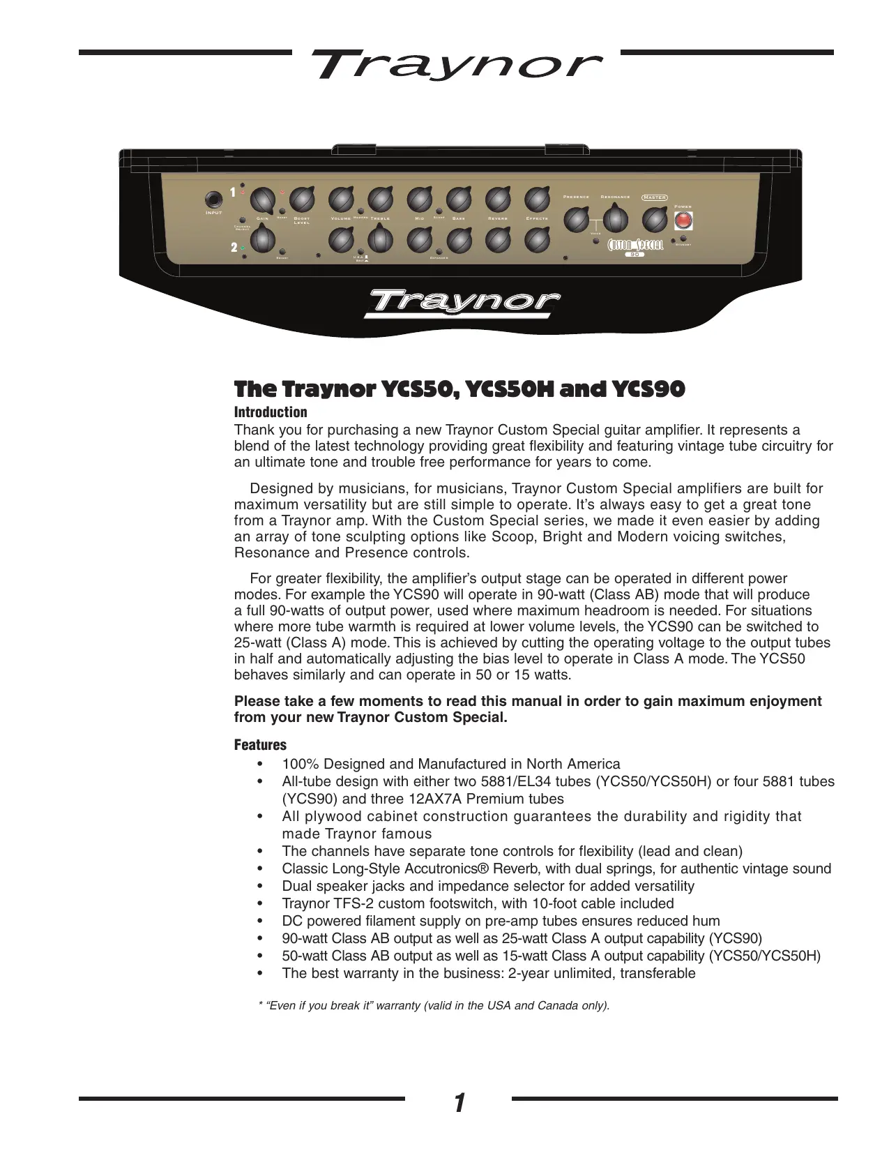
The Traynor YCS50, YCS50H and YCS90
Introduction
Thank you for purchasing a new Traynor Custom Special guitar amplifier. It represents a blend of the latest technology providing great flexibility and featuring vintage tube circuitry for an ultimate tone and trouble free performance for years to come.
Designed by musicians, for musicians, Traynor Custom Special amplifiers are built for maximum versatility but are still simple to operate. It's always easy to get a great tone from a Traynor amp. With the Custom Special series, we made it even easier by adding an array of tone sculpting options like Scoop, Bright and Modern voicing switches, Resonance and Presence controls.
For greater flexibility, the amplifier's output stage can be operated in different power modes. For example the YCS90 will operate in 90-watt (Class AB) mode that will produce a full 90-watts of output power, used where maximum headroom is needed. For situations where more tube warmth is required at lower volume levels, the YCS90 can be switched to 25-watt (Class A) mode. This is achieved by cutting the operating voltage to the output tubes in half and automatically adjusting the bias level to operate in Class A mode. The YCS50 behaves similarly and can operate in 50 or 15 watts.
Please take a few moments to read this manual in order to gain maximum enjoyment from your new Traynor Custom Special.
Features
100% Designed and Manufactured in North America
- All-tube design with either two 5881/EL34 tubes (YCS50/YCS50H) or four 5881 tubes (YCS90) and three 12AX7A Premium tubes
- All plywood cabinet construction guarantees the durability and rigidity that made Traynor famous
The channels have separate tone controls for flexibility (lead and clean)
Classic Long-Style Accutronics® Reverb, with dual springs, for authentic vintage sound
Dual speaker jacks and impedance selector for added versatility
- Traynor TFS-2 custom footswitch, with 10-foot cable included
DC powered filament supply on pre-amp tubes ensures reduced hum
90-watt Class AB output as well as 25-watt Class A output capability (YCS90)
- 50-watt Class AB output as well as 15-watt Class A output capability (YCS50/YCS50H)
The best warranty in the business: 2-year unlimited, transferable

Channel 1
Channel 1 is the lead/overdrive channel and is selected in one of two ways, via the Channel Select switch on the control panel, or via the Channel Select button on the supplied footswitch pedal. The yellow LED, located next to the Channel 1 Gain control, illuminates when Channel 1 is active.
Note: Plugging in the footswitch deactivates the panel-mounted Channel and Boost controls.
Gain & Volume Controls ③ ⑤
Channel 1 uses a Gain control in conjunction with a Volume control to control the amount of tube-based overdrive and volume. The Gain control is used to adjust the amount of overdrive, while the Volume control allows you to set the actual loudness of the channel.
Boost Switch and Boost Level Control ④
A boost circuit is provided to help achieve more overdrive for leads. The boost can be selected via the front panel switch or through the supplied footswitch pedal. A Red LED illuminates to indicate when the boost is active. The Boost Level controls the amount of boost applied.
Modern Switch ⑥
The Modern switch controls the frequency range that the tone controls work in. You can choose from a more vintage sound with emphasis on the midrange or a deeper "modern" sound.
Scoop Switch ⑨
The Scoop provides deep midrange cut with a bass boost to get that deep, chunky sound.
Channel 1 Tone Controls ⑦
The Treble, Middle and Bass tone controls help you shape your sound. They are post-gain and pre-volume. These are active only when Channel 1 is selected.
Reverb Control ⑨
The Reverb Return controls the amount of reverb return from the internal Accutronics® spring reverb tank. This control is active only when Channel 1 is active.
Effects Control
This controls the amount of return signal from the external effect plugged into the rear panel Efx Rtn jack. This control is active only when Channel 1 is active.
Channel 2
Channel 2 can be used as the clean channel and the layout is similar to Channel 1, with independent Gain, Volume, Treble, Middle and Bass tone controls. When channel 2 is active the green LED located next to the Channel 2 Gain control is illuminated.
Brightness Switch ⑫
Channel 2 includes a Brightness switch that activates a circuit to provide additional treble boost to help make your tone sparkle.
U.S.A. / Brit Switch 14
The U.S.A. / Brit switch changes the 'location' of the 'tone stack' in the signal chain. The U.S.A. mode configures the YCS amplifier like the classic U.S.A. amps of the past by locating the Gain control after the tone controls. This configuration provides maximum headroom to help achieve a crystal clear, clean sound. In the Brit mode, the Gain control is located at the front-end (before the tone stage) and will start to produce saturation when turned up, akin to classic British designs.
Expander Switch 16
The Expander adds deep bottom and sparkling highs to Channel 2.
Channel 2 Tone Controls ⑤
The Treble, Middle and Bass tone controls help you shape your sound. They are pre-gain / pre-volume in the U.S.A. mode and post-gain / pre-volume in Brit mode. These are active only when Channel 2 is selected.
Reverb Control ⑦
The Reverb Return controls the amount of reverb return from the internal Accutronics® spring reverb tank. This control is active only when Channel 2 is active.
Effects Control 18
This controls the amount of return signal from the external effect plugged into the rear panel EFX RTN jack. This control is active only when Channel 2 is active.
Master Controls
Presence, Resonance Controls and the Voice Switch 19 20 21
The Presence Control shapes the overall brightness of both channels. The Resonance Control adjusts the damping factor of the speakers in the bass frequencies, helping loosen or tighten the bottom end. Turning the Resonance control up (clockwise) will add more rumble, turning it down (counter-clockwise) tightens up the bottom end.
The voice switch bypasses the Resonance and Presence controls. The amplifier is now operating in an "open loop" mode which permits full tube tone without alteration.
Master Volume 2
The Master volume controls the overall level of both channels.
Standby Switch and Indicator 23
This switch controls the high voltage power being supplied to the output tubes. This mode effectively keeps the tubes warmed up when the amp is not in use. The large, jewel indicator on the front panel glows Red when the amp is fully powered-up and changes to Yellow when the high voltage circuit has been turned off. Putting the amp into Standby mode (i.e. during set breaks) shuts off the amplifier output stage and effectively increases tube life by reducing wear on the output tubes.
Note: The preamp will remain active when in Standby mode allowing the use of the D.I. Output for direct recording without sound coming from the speakers.

Rear Panel
Amp Mode 25
The YCS amplifiers can be operated in two different modes, full-power class AB and low-power class A. When operating in full-power mode, the full voltage is applied to the output and preamp tubes and the amplifier operates in a traditional class AB configuration. Selecting the low-power mode cuts the operating voltage by half and increases the bias in the output tubes to full class A operation. This allows the output and preamp to operate with a great deal of more 'saturation.' Operating in Low Power mode also results in extended tube life.
XLR Balanced D.I. Line Out Jack 25
For maximum versatility, The YCS amplifiers have an XLR D.I. Line Out. The signal sent from this output is post-master and has the Traynor Dyna-Sound speaker simulator compensation. This speaker output does not remain active when the amplifier is in standby mode so the YCS amplifier can be used as a preamp for recording.
Note: The balanced XLR line output signal is affected by all the tone and volume controls, but not the Master volume or the Reverb. It is a "dry" signal so that PA and recording engineers may add reverb at the mixer.

EFX Send, Return Jacks and Controls 27 29
The Send and Return jacks of the YCS amplifiers allow convenient use of an external effect unit. Simply connect a 1/4 -inch cable to the Send jack and then connect this cable to the input of your effects unit. To send the processed signal back to the YCS amplifier, connect the output of the effects unit to the Rtn jack on the YCS amplifier. The Efx Send Level control (located next to the Efx Send and Return jacks) enable fine adjustments to the signal being sent to, and returning from external effects units.
The 14 -inch TRS Send jack is used as part of an effects loop, in conjunction with the Rtn jack. The -10dBu output is ideal for most guitar effects pedals and professional signal processors. You can also use this output to slave the YCS amplifier with another guitar amplifier by plugging into the return jack of the destination amplifier which will be the slave amplifier.
The 1/4 -inch TRS Return jack is used as your return jack for your effects loop. The individual Effects Rtn controls are used to control the amount of effect returning to the amplifier.

Note: The Effects Send and Return have been designed with a parallel effects loop. This design allows the true signal (bypassed) to be blended with the external effect using the Effects blend control. The parallel loop also features balanced jacks which enables better integration with rackmount effects processors.
Amp In and Preamp Out Jacks 29
The Amp In and Pre-Amp Out jacks can be used as a loop-thru for guitar pedals or other effect devices. Simply plug a 14 -inch cable from the Pre-Amp Out jack of the YCS amplifier into the input of the effect unit or pedal. Plug another 14 -inch cable from the output of the effect unit, or pedal, to the Amp In jack of the YCS amplifier. This is handy when you have devices that are intended to be inserted into the signal chain.

Tech Note: The signal level at this point is -10dBV so it will work with most guitar effect pedals as well as professional rack equipment.
Footswitch Jacks 30
Connecting a footswitch to the 14 -inch TRS Footswitch jack deactivates the control panel mounted Channel Select and Boost switches. These functions are then activated exclusively by the pedal. The included footswitch features dual-latching switches, each with a separate LED indicator. There is also a 14 -inch footswitch jack enabling the reverb and effects returns to be defeated.
The switching is accomplished with internal relays so there is no audio flowing through the footswitch cable. Footswitch-induced noise is never an issue. The YCS50, YCS50H and YCS90 are compatible with most aftermarket latching dual-footswitch pedals.
External Speaker Jack/s and Impedance Selector Switch 32
The dual 1 / 4 -inch jacks allow convenient connection of external speaker cabinets. By disconnecting the internal 12-inch Celestion® speaker(s), up to two 8-ohm external cabinets can be used.
Note: Insure that speakers are properly connected and that the impedance selector is set to the appropriate position before operating the amplifier.
Speaker Cabinets
You can either connect speakers in parallel or series. Most speaker enclosures have parallel output jacks that enable users to chain speaker extension cabinets together. Series connections are rarely used.
The easiest way to describe this is if you have two 8-ohms speaker cabinets connected in parallel the resulting impedance would be 4-ohms (16-ohms if they were wired in series).
The formula to calculate Total Impedance for a parallel system is:
$$ 1 / R _ {T} = 1 / R _ {1} + 1 / R _ {2} + 1 / R _ {3} + 1 / R _ {4} \dots $$
R = Rated Speaker Impedance
R_T = Total Speaker Impedance
R_1 = Speaker Impedance
Examples (Speaker cabinets connected in parallel)
One 4-ohm cabinet = 4-ohms
Two 4-ohm cabinets = 2-ohms
Four 4-ohm cabinets = Not Recommended
One 8-ohm cabinet = 8-ohms
Two 8-ohm cabinets = 4-ohms
Four 8-ohm cabinets = 2-ohms
One 16-ohm cabinet = 16-ohms
Two 16-ohm cabinets = 8-ohms
Four 16-ohm cabinets = 4-ohms
Eight 16-ohm cabinets = 2-ohms
Replacement Tube Selection & Bias**
These YCS amplifiers come from the factory equipped with matched 5881 (YCS50H uses matched EL34 output tubes) output tubes. The circuitry has been designed to accommodate any type of EL34/6CA7 as well as any type of 6L6/5881 output tubes (as long as the four, or two, output tubes are of a matching type). The amplifier has also been equipped with bias sensing points for each of the output tubes as well as a recessed bias adjustment trim pot that can all be accessed without removing the chassis from the box. This makes tube replacement quick and easy.

**We recommend adjusting the zero signal bias to +75mV + / - 10mV DC at each of the test points. Bias adjustment should be done with the amplifier configuration in the 50 Watt mode (YCS50) or 90 Watt mode (YCS90). Please refer servicing to qualified personnel.
Footnotes for YCS50, YCS50H and YCS90
The four gain stages in the YCS series amplifiers have been configured to maximize the available gain at each stage which provides the most flexibility possible. If all of the gain stages are set too high (simultaneously) the amplifier or the guitar will almost certainly feed back. There is always a limit to how much "total" gain you can achieve without feedback or oscillation; these amplifiers are capable of enough gain to test the limits of any tube or guitar.
The amount of reverb return available is a function of the Reverb control on the channel and the Master Volume. If "both" controls are set too high the reverb tank will feed back. This is to allow you to play with extremely "wet" sounds at lower volume levels.
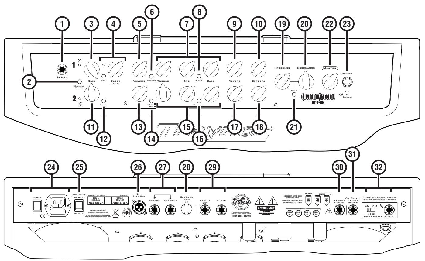
① Input Jack - 1/4-inch jack
② Channel Select Switch
③ Channel 1 Gain Control
④ Channel 1 Boost Switch and Level Control
⑤ Channel 1 Volume Control
⑥ Channel 1 Modern Switch
⑦ Channel 1 Tone Controls
⑥ Channel 1 Scoop Switch
Channel 1 Reverb Control
Channel 1 Effects Control
① Channel 2 Gain Control
⑥ Channel 2 Bright Switch
⑬ Channel 2 Volume Control
① Channel 2 U.S.A./ Brit Switch
⑤ Channel 2 Tone Controls
Channel 2 Expander Switch
⑦ Channel 2 Reverb Control
Channel 2 Effects Control
Presence Control
20 Resonance Control
Voice Switch
Master Volume Control
23 Standby Switch and Indicator
_i Power Switch and Receptacle
25 Amp Mode Switch
D.I. Line Out - XLR jack
EFX Send and EFX Return - 1 / 4 -inch jacks
EFX Send Level Control
29 DAmp In and Preamp Out - 1 / 4 -inch jacks
EFX / Reverb Footswitch Connector - 1/4-inch TRS jack
Channel Select / Boost Footswitch Connector - 1/4-inch TRS jack
Speaker Jack/s and Impedance Selector Switch - 1/4-inch jack/s
Les Traynor YCS50, YCS50H et YCS90
Introduction
Type: Combo / Head / Combo Guitar Amplifiers
(ohms): 8 / na / 8
Watts): 50 / 50 / 90
(ohms): 4 ohms on all models
2 cycle: 60 / 60 / 110
Power): 1 12-inch 60 watts / n.a. / 2 12-inch 120 watts
Input Channels: 1
Channel 1 - inputs: 1-1/4-inch shared with channel 2
Channel 1 - controls: Gain, Boost Level, Volume, Treble, Mid, Bass,
Reverb, Effects Return
Channel 1 - switches: Boost, Modern, Scoop
Channel 2 - inputs: 1-1/4-inch shared with channel 1
Channel 2 - controls: Gain, Volume, Treble, Mid, Bass, Reverb, Effects
Return
Channel 2 - switches: Bright, USA/Brit, Expander
Channel Switching: 2 Channels, Boost on Channel 1, Footswitchable
Master Volume Control: Yes
Main Tone Controls: Presence, Resonance, Voice
Master Outputs: Preamp Out (TRS), D.I. Out (XLR), Effects Send
with Control (TRS)
Line Out (type / configuration): Preamp Out (TRS), D.I. Out (XLR), Effects Send
with Control (TRS)
Line Out Sensitivity (Vrms):
Effects Volume:
Effects Loop / Location: Rear
Effects Footswitch / Function: Reverb and Effects Return Footswitchable
Effects Return Sensitivity (Vrms): 308
Internal Reverb / Effects: Accutronics Dual Spring Long Tank
LED Indicators: Ch1, Ch2, Boost, Power/Standby
Protection: Mains Fuse
Output / location: 1 (rear panel)
Other Features: Class A low power mode 15/15/25 Watts
Ds (DWH, inches): 10.5x25x21.5 / 10x27x11 / 10.5x27.5x21.5
ions (DWH, cm): 27 × 64 × 55 / 25 × 69 × 28 / 27 × 70 × 55
Weight (lbs/kg): 48lbs./22kg / 38lbs./17kg / 51lbs./23kg
Specifications
Puisance @ impedance minimum (Watts): 50 / 50 / 90
Model TYPE: YS1064 Model TYPE: YS1067 Block Diagram for YCS50/50HIYCS90
DESIGNED AND MANUFACTURED BY YORKVILLE SOUND
12AX7 12AX7 12AX


DISCONNECT POWER WHEN REPLACING TUBES

DEBRANCHIC'APPEAREAVAN DE REMPLACER LES LAMPEs


CS50


Traynor Two Year Warranty
Unlimited Warranty
Your Traynor two year unlimited warranty on this product is transferable and does not require registration with Yorkville Sound or your dealer. If this product should fail for any reason within two years of the original purchase date, simply return it to your Traynor dealer with original proof of purchase and it will be repaired free of charge.
Freight charges, consequential damages, weather damage, damage as a result of improper installation, damages due to exposure to extreme humidity, accident or natural disaster are excluded under the terms of this warranty. Warranty does not cover consumables such as vacuum tubes, bulbs or batteries beyond 90 days of original purchase. See your Yorkville dealer for more details. Warranty valid only in Canada and the United States.
Garantie Illimitée
Voice: (905) 837-8481 Voice: (716) 297-2920
Fax: (905) 837-8746 Fax: (716) 297-3689

Yorkville
550 Granite Court 4625 Witmer Industrial Estate
Pickering, Ontario Niagara Falls, New York
L1W-3Y8 CANADA 14305 USA

WEB: www.yorkville.com
Niagara Falls, New York
14305 USA
Voice: (716) 297-2920
Fax: (716) 297-3689

Quality and Innovation Since 1963
Printed in Canada
Manual-Owners-YCS50-YCS50H-YCS90-00-1v7 - May 11/2009