
YS1053 - Guitar amplifier TRAYNOR - Free user manual and instructions
Find the device manual for free YS1053 TRAYNOR in PDF.
User questions about YS1053 TRAYNOR
0 question about this device. Answer the ones you know or ask your own.
Ask a new question about this device
Download the instructions for your Guitar amplifier in PDF format for free! Find your manual YS1053 - TRAYNOR and take your electronic device back in hand. On this page are published all the documents necessary for the use of your device. YS1053 by TRAYNOR.
USER MANUAL YS1053 TRAYNOR
G U I T A R A M P L I F I E R
IMPORTANT SAFETY INSTRUCTIONS

This lightning flash with arrowhead symbol, within an equilateral triangle, is intended to alert the user to the presence of uninsulated "dangerous voltage" within the product's enclosure
that may be of sufficient magnitude to constitute a risk of electric shock to persons.
The exclamation point within an equilateral triangle is intended to alert the user to the presence of important operating and maintenance (servicing) instructions in the ccompanying the appliance.
Instructions pertaining to a risk of fire, electric shock, or injury to a person
CAUTION: TO REDUCE THE RISK OF ELECTRIC SHOCK, DO NOT REMOVE COVER (OR BACK).
NO USER SERVICEABLE PARTS INSIDE.
REFER SERVICING TO QUALIFIED SERVICE PERSONNEL.
Read Instructions: The Owner's Manual should be read and understood before operation of your unit. Please, save these instructions for future reference and heed all warnings.
Clean only with dry cloth.
Packaging: Keep the box and packaging materials, in case the unit needs to be returned for service.
Warning: To reduce the risk or fire or electric shock, do not expose this apparatus to rain or moisture. Do not use this apparatus near water!
Warning: When using electric products, basic precautions should always be followed, including the following:
Power Sources
Your unit should be connected to a power source only of the voltage specified in the owners manual or as marked on the unit. This unit has a polarized plug. Do not use with an extension cord or receptacle unless the plug can be fully inserted. Precautions should be taken so that the grounding scheme on the unit is not defeated.
Hazards
Do not place this product on an unstable cart, stand, tripod, bracket or table. The product may fall, causing serious personal injury and serious damage to the product. Use only with cart, stand, tripod, bracket, or table recommended by the manufacturer or sold with the product. Follow the manufacturer's instructions when installing the product and use mounting accessories recommended by the manufacturer.
The apparatus should not be exposed to dripping or splashing water; no objects filled with liquids should be placed on the apparatus.
Terminals marked with the "lightning bolt" are hazardous live; the external wiring connected to these terminals require installation by an instructed person or the use of ready made leads or cords.
Ensure that proper ventilation is provided around the appliance. Do not install near any heat sources such as radiators, heat registers, stoves, or other apparatus (including amplifiers) that produce heat.
No naked flame sources, such as lighted candles, should be placed on the apparatus.
Power Cord
Do not defeat the safety purpose of the polarized or grounding-type plug. A polarized plug has two blades with one wider than the other. A grounding type plug has two blades and a third grounding prong. The wide blade or the third prong are provided for your safety. If the provided plug does not fit into your outlet, consult an electrician for replacement of the obsolete outlet. The AC supply cord should be routed so that it is unlikely that it will be damaged. If the AC supply cord is damaged DO NOT OPERATE THE UNIT.
Unplug this apparatus during lightning storms or when unused for long periods of time.
Service
The unit should be serviced only by qualified service personnel.
SUIVEZ TOUTES LES INSTRUCTIONS
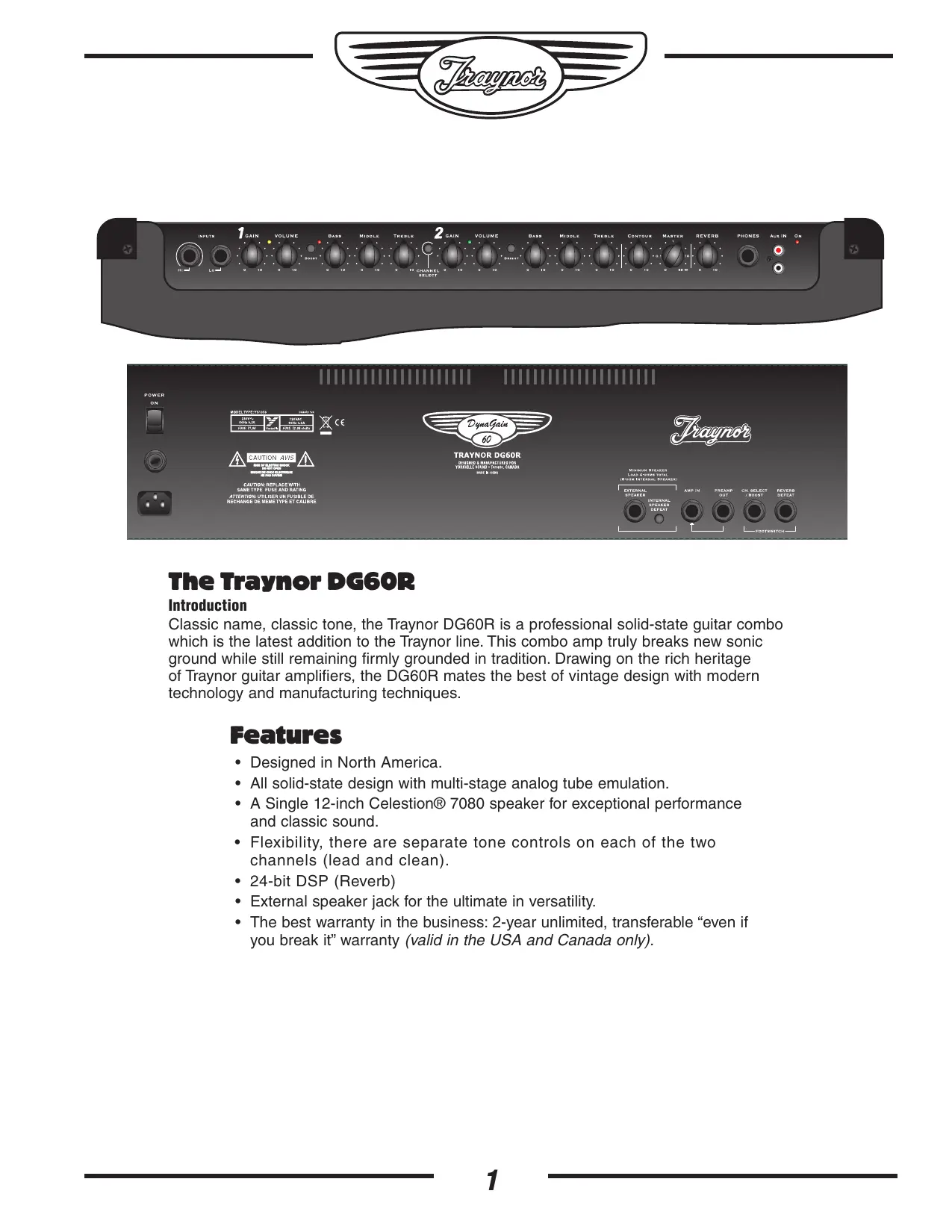
Classic name, classic tone, the Traynor DG60R is a professional solid-state guitar combo which is the latest addition to the Traynor line. This combo amp truly breaks new sonic ground while still remaining firmly grounded in tradition. Drawing on the rich heritage of Traynor guitar amplifiers, the DG60R mates the best of vintage design with modern technology and manufacturing techniques.
Features
- Designed in North America.
- All solid-state design with multi-stage analog tube emulation.
- A Single 12-inch Celestion® 7080 speaker for exceptional performance and classic sound.
- Flexibility, there are separate tone controls on each of the two channels (lead and clean).
24-bit DSP (Reverb) - External speaker jack for the ultimate in versatility.
- The best warranty in the business: 2-year unlimited, transferable "even if you break it" warranty (valid in the USA and Canada only).


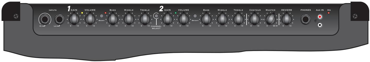
Top
① Input Jacks - two 1/4 -inch phone jacks. Hi and Lo gain.
② Channel 1 indicator LED - Illuminates yellow when active.
③ Channel 1 Boost Switch - Activates the boost circuitry for extra crunch.
④ Boost LED - Illuminates red when the boost is active.
⑤ Channel 1 Gain and Volume controls.
⑥ Channel 1 Tone Controls – Treble, Bass, and Middle.
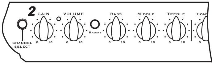
⑦ Channel Select Switch - Channel 1 is optimized for lead, Channel 2 for clean sound
Channel 2 Gain and Volume Controls.
Channel 2 Indicator LED - Illuminates green when active.
Channel 2 Brightness Switch - Add sparkle to your clean sound.
11 Channel 2 Tone Controls - Treble, Bass, and Middle.
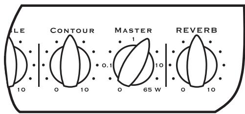
12 Contour Control - Adjusts the character from vintage tones to modern sounds.
Master Control - Adjusts the amount of output power available.
14 Reverb Control – Adjusts the 24-bit DSP reverb level for both channels
15 Headphone Jack - Speaker emulated output. Can also be used as a line out.
16 Aux In – For connection of CD-player or an MP3 player.
⑦ Power Indicator - Illuminates green when the amplifier is turned on.
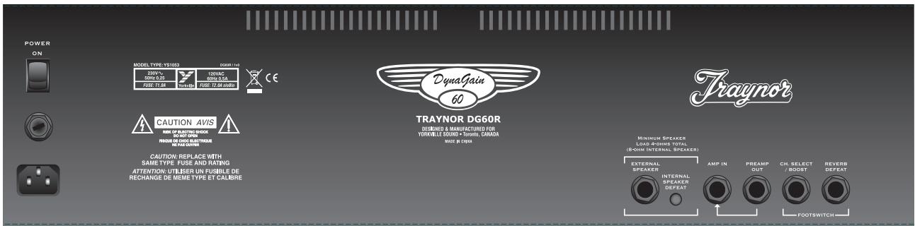
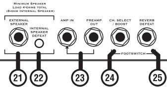
Rear
18 Power Receptacle.
Fuse holder.
20 Power Switch
② Extension Speaker jack -1/4 -inch phone jack.
22 Internal Speaker Defeat switch- disconnects the internal speaker from the amplifier.
23 Amp In and Preamp Out jacks - 14 -inch phone input and output jacks.
② Channel Select Footswitch jack - uses a 1 / 4 -inch TRS standard latching dual-footswitch.
Effects Defeat jack- uses a 1 / 4 -inch TRS standard latching dual-footswitch.
Channel 1
Channel 1 is the lead/ overdrive channel and is selected in one of two ways, via the Channel Select switch on the control panel, or via the Channel Select button on the footswitch pedal. A
yellow LED located next to the Channel 1 Volume control illuminates when Channel 1 is active.
*Note: Plugging in the footswitch deactivates the panel-mounted Channel and Boost controls.

Master Controls
Master Control 13
This Master control not only adjusts the overall volume level of the DG60R but also provides control of the output power. The DG60R's
power amplifier has been designed to behave akin to a "tube" power amplifier stage and will provide the same level of compression and soft clipping at all volume levels. The dial has been calibrated to let you know how many watts you're working with.
Gain & Volume Controls ⑤ ⑧
Channel 1 uses a Gain control in conjunction with a Volume control to determine the amount of tube-emulated overdrive and volume. The Gain control is used to adjust the amount of overdrive, while the Volume control allows you to set the actual loudness of the amplifier.
Boost Switch ③ ④
The boost circuit enables you to achieve 'a-bit-more' overdrive for leads when needed. The Boost can be selected via the front panel switch or through the footswitch pedal. A red LED illuminates to indicate when the boost is active.
Channel 1 Tone Controls
The Treble, Bass, and Middle tone controls are used to help shape your sound. They are post-gain and pre-volume. These are active only when Channel 1 is selected.
Channel 2
Channel 2 is the clean channel. The layout is the same as that of Channel 1, with independent Gain, Volume, Treble, Bass, and Middle tone controls. When channel 2 is active the green LED located next to the Channel 2 Volume control is illuminated.
Brightness Switch 10
Channel 2 includes a Brightness switch that activates circuitry providing an additional treble boost, which helps make your tone sparkle.
Contour Control 12
The Contour control adjusts the amount of mid-scoop, which allows you to dial-in character to your tone from vintage to modern, and all points in between.
Reverb Control 10
The Reverb control adjusts the overall reverb level for both channels. The DG60R is equipped with a 24-bit DSP based effects processor for lush large room reverb.
EFX / Line Preamp Out & Amp In Jacks 23
The Preamp Out and Amp In jacks of the DG60R allow convenient use of an external effects unit. Simply connect a 1 / 4 -inch phone cable to the Preamp Out jack and connect this cable to the input of your effects unit. To send the processed signal back to the DG60R, connect the output of the effects unit to the Amp In jack of the DG60R.
The 14 -inch T.R.S. Preamp Out jack can also be used as a direct line out. The -10 dBu output is ideal for most guitar effects pedals and professional signal processors. You can also use this output to slave the DG60R with another guitar amplifier by plugging into the Amp In jack of the slave amplifier.
The 1/4 -inch T.R.S. Amp In jack accepts an input signal that is passed to the power amplifier, so it can be used as a power amp in. And, since the Master control section affects the Amp In signal, you can use Contour and Reverb to further shape your tone.
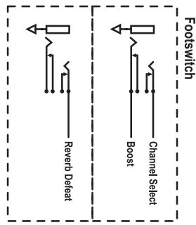
Footswitch Jack (Channel Select/Boost) 24
When connected, the footswitch pedal is the exclusive control for the Channel Select and Boost functions, bypassing the switches on the DG60R's control panel. It features dual-latching switches, each with a separate LED indicator.
Footswitch-induced noise is never an issue. The switching is accomplished with internal FET's so there is no audio flowing through the footswitch cable. The DG60R is compatible with most aftermarket latching dual-footswitch pedals although we do recommend the Traynor TFS-2B latching dual-footswitch, with 10-foot cable.
Reverb Defeat Jack 25
Connecting a footswitch to the rear mounted Reverb defeat jack can defeat the internal effects. A footswitch can be used for this purpose. Again, since switching is accomplished using internal FET's, no audio is flowing through the footswitch cable and noise is not an issue.
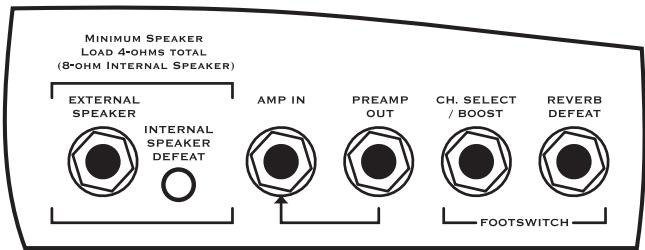
External Speaker Jack and Internal Speaker Defeat Switch 21 22
The chassis mounted 1 / 4 -inch jack allows convenient connection of an 8-ohm external speaker cabinet. If you disconnect the internal 12-inch Celestion® 7080 speaker by
depressing the Internal Speaker Defeat switch, you can connect up to two 8-ohm external cabinets (minimum speaker load of 4-ohms).
Headphone Jack & Speaker Defeat 15
The headphone jack can be used with any stereo headphones. The headphone signal is post-preamp and pre-master. This means the signal is affected by all controls, including reverb, but not the Master Volume. For practicing silently, don't forget to disengage the speaker outputs by depressing the Speaker Defeat button.
Specifications
| Type | Solid-State Guitar Amplifier |
| Cabinet Program Power (Watts) | 65 |
| Cabinet Impedance (ohms) | 8 |
| Power @ 8-ohm impedance (Watts) | 65 |
| Minimum Impedance (ohms) | 4 |
| Burst Power - 2 cycle | 85-watts |
| Speaker Configuration - LF (Size / Power) | 12 inch / 75 Watts |
| Input Channels | Hi / Lo |
| Channel 1 - inputs | 1/4 inch phone |
| Channel 1 - controls | Gain, Volume, Treble, Bass, Middle |
| Channel 1 - switches | Boost |
| Channel 2 - inputs | Shares ch 1 input |
| Channel 2 - controls | Gain, Volume, Treble, Bass, Middle |
| Channel 2 - switches | Bright |
| Channel Switching | Yes / Footswitchable |
| Master Volume Control | Yes |
| Main Tone Controls | Contour |
| Input Sensitivity (mV) | 20 |
| Master Outputs | Preamp Out / Headphone Out |
| Line Out (type / configuration) | 1/4 inch TRS / Rear (Effects Send) |
| Line Out Sensitivity (Vrms) | 300mV |
| Effects Volume | Reverb |
| Effects Loop / Location | Post Preamp / Rear |
| Effects Footswitch / Function | Yes / Channel Select, Boost |
| Effects Return Sensitivity (Vrms) | 300mV |
| Internal Reverb | 24-bit DSP |
| LED Indicators | Channel Select, Boost, Power |
| Protection | Short Circuit, Thermal |
| External speaker output / location | 1/4-inch, Rear / Internal Speaker Defeat Switch |
| Headphone Jack | Yes / Front Panel / Dyna-Sound Speaker Emulation |
| Other Features | 3-Stage Dynamic Tube Emulation |
| Transconductance Power Amplifier for further tube | |
| All Plywood Contraction | |
| vintage-style cloth grille | |
| Dimensions (DWH, inches) | 10 x 24.5 x 18 |
| Dimensions (DWH, cm) | 25 x 62 x 46 |
| Weight (Ibs / kg) | 40 / 18 |
Le Traynor DG60R
Introduction
CAUTION REPLACE WITH SOLDERING THE CRYSTAL BY USING ATTENTION: UNEITHER UN FUSIBLE DE PASTORIUM OR ANYTHING ELSE.

TRAYNOR DG60R
DESIGNED & MANUFACTURED FOR
YORKVILLE SOUND • Teema, CANADA
NADE M. CHINA

Dessus
Volume - Effets Reverb
Boucle d'effets / Location Post Préamp/Arriere
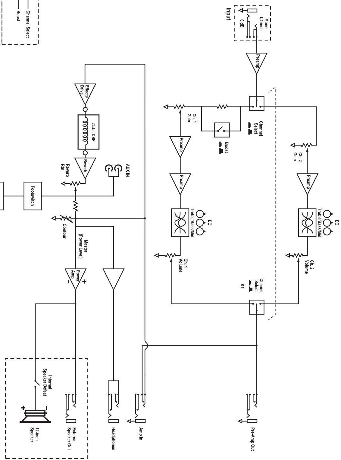
MODELTYPE: YS1053 Block Diagram for DG6OR DESIGNED AND MANUFACTURED BY YORKVILLE SOUND
Zaynot
Traynor Two Year Warranty
Unlimited Warranty
Your Traynor two year unlimited warranty on this product is transferable and does not require registration with Yorkville Sound or your dealer. If this product should fail for any reason within two years of the original purchase date, simply return it to your Traynor dealer with original proof of purchase and it will be repaired free of charge.
Freight charges, consequential damages, weather damage, damage as a result of improper installation, damages due to exposure to extreme humidity, accident or natural disaster are excluded under the terms of this warranty. Warranty does not cover consumables such as vacuum tubes, bulbs or batteries beyond 90 days of original purchase. See your Yorkville dealer for more details. Warranty valid only in Canada and the United States.
Garantie Illimitée
Niagara Falls, New York
14305 USA
Voice: (716) 297-2920
Fax: (716) 297-3689
