
C2- 650 - Audio Amplifier BEGLEC - Free user manual and instructions
Find the device manual for free C2- 650 BEGLEC in PDF.

| Product type | Professional audio amplifier |
| Brand | BEGLEC |
| Model | C2-650 |
| Output power (stereo 8 Ω) | 2 × 400 W RMS |
| Output power (stereo 4 Ω) | 2 × 650 W RMS |
| Output power (bridged 8 Ω) | 1000 W RMS |
| Frequency response | 10 Hz – 50 kHz (-1.5 dB) |
| Input sensitivity | 0.77 V / 26 dB / 1.4 V |
| Input impedance | 20 kΩ (active balanced) |
| Signal-to-noise ratio | >95 dB (A-weighted) |
| Damping factor | >200 (1 kHz, 8 Ω) |
| Slew rate | 35 V/μs |
| Protection | Short circuit, current limiting, DC fault, mains fuse, thermal cutoff, power on/off transients, soft start, limiter |
| Cooling | Variable speed fan |
| Power supply | 230 V ~ 50 Hz |
| Dimensions (W × D × H) | 483 × 430 × 132 mm |
| Inputs | 2 × XLR balanced, 2 × 6.35 mm TRS balanced jack |
| Speaker outputs | Screw terminals and Speakon connectors |
| Operating modes | Stereo, bridged (mono), parallel |
| LED indicators | Power (green), Bridge (green), Parallel (green), Protection (yellow), Clip/limit (red) |
| Special functions | Servo-controlled power supply, soft start, input sensitivity selector, ground lift switch |
| Maintenance | Regularly clean dust filters with a vacuum cleaner; do not use water |
| Safety | Do not block ventilation openings; check mode switch; use an appropriate power source |
| Fuse | Same type and rating when replacing |
Frequently Asked Questions - C2- 650 BEGLEC
User questions about C2- 650 BEGLEC
0 question about this device. Answer the ones you know or ask your own.
Ask a new question about this device
Download the instructions for your Audio Amplifier in PDF format for free! Find your manual C2- 650 - BEGLEC and take your electronic device back in hand. On this page are published all the documents necessary for the use of your device. C2- 650 by BEGLEC.
USER MANUAL C2- 650 BEGLEC
The PS series amplifiers are high quality and performance amplifiers. To get the maximum result, it features a servo system, power supply and a fan with adjusted speed.
The main features include:
- XLR and 1 / 4' jack balanced input
- Input sensitivity switch
Output: Speacon and speaker terminals - Stereo, bridge and parallel switch
Soft start
Perfect protection system for the speakers - Thermal cut off (85°C protection)
Current limiter
2. Precautions
- Use an adequate power source.
- Do not turn on several amplifiers at the same time.
- Do not allow that the ventilation holes in the front or in the back of the amplifier are blocked in any way.
- Input level controls are present on each channel.
Output can use speacon or binding posts. - Please check carefully if the mode switch is in the correct position: stereo, bridge or parallel.
- Clean the amplifier regularly. Especially the dustfilters located behind the front panel should be cleaned regularly.
- Use a vacuumcleaner to remove dust inside the amplifier. Never use water.
- In case of a defect, contact your dealer.
3. Major Operation Controls
A. Front Panel
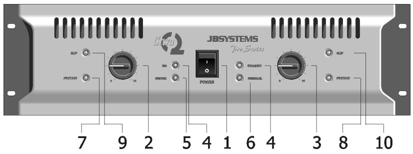
1. Power ON/OFF
With this switch, you turn the amplifier on. You will note a brief delay in the switching on, due to the soft start.
2/3. Input Level Control
With these rotary VR's, you can adjust the input level of each side. In bridge or parallel mode, only the left VR is active.
4. Power ON Indicator (green)
Indicates that the amplifier is on.
5. Bridge Mode Indicator (green)
Indicates that the amplifier is working in bridge mode. In this case only the left channel needs an input signal.
6. Parallel Mode Inindicator (green)
Indicates that the amplifier is running in parallel mode. The input signal must only be applied to the left channel.
7/8. Protection LED (yellow)
The led light up when the amplifier is overheated (thermal protection) or when something is wrong with the amplifier.
9/10. Peak Level (clip) Indicator (red)
These led will light up in two situations:
a. When the output signal has reached its maximum level, the LED will light. This goes with a distortion of the audio signal. When this occurs, reduce the input level.
b. When you have an input signal and the clip led lights continuously, it means that you have a short circuit on the output. Please turn of the amplifier and check out the problem on the load.
B. Rear Panel
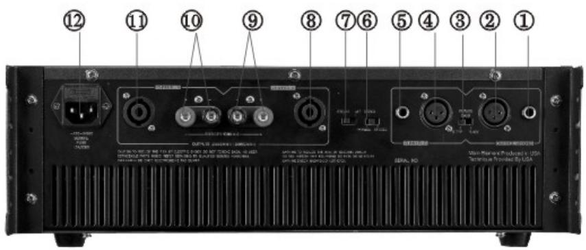
1/5. 1/4' Jack Input Connectors
You can use a balanced or unbalanced input signal.
- Unbalanced: use a mono jack. Tip=signal, Sleeve=ground.
- Balanced: use a stereo jack. Tip=signal+, Ring=signal-, Sleeve=ground.
2/4. XLR Input Connectors
You can use a balanced or unbalanced input signal.
- Unbalanced: Pin 1=ground, Pin 2=signal, Pin 3=ground=pin 1.
- Balanced: Pin 1=ground, Pin 2=signal+, Pin 3=signal-.
3. Input Sensitivity Switch
The position of this switch is very important and depends on the output level of your preamplifier. There are 3 positions:
Full power output at 0,77V input level
26 dB gain of the input signal
Full power output at 1,4V input level. Use this position with JBSystems mixers.
6. Mode Selector
You can select between stereo mode, bridge mode or parallel mode.
- When you use stereo mode, you have to connect the input and output of both channels.
- When you use bridge mode, the input signal must be applied to the left channel only.
- When you use parallel mode, the input signal must be applied to the left channel only.
7. Ground Lift Switch
Setting this switch to the position "left" breaks the ground loop between the amplifier and the chassis ground of various components.
8/11. Speacon Output
When you work in stereo mode, you can use the speacon for connecting your speakers.
The connections are:
1+ and 2+: signal
1- and 2- : ground
9/10. Binding Posts
In stereo mode:
Red = signal
Black = ground
12. Power Cord Socket and Fuse
When the fuse is broken, replace by the same type and value.
4. Operation in bridge mode and parallel mode
A. Bridge Mode
- Turn the amplifier off
- Connect the input to CH1 (left) only
- Connect your speaker system across the red terminals
Red terminal CH1: signal +
Red terminal CH2: signal - (ground)
-
The minimum impedance of your speaker system should be 8 Ohm
-
Set the mode switch on BRIDGE
- Turn the amplifier on
B. Parallel Mode
- Turn the amplifier off
- Connect the input to CH1 (left) only
- Connect your speakers in the normal way, as you should do in stereo mode
- Set the mode switch on PARALLEL
- Turn on the amplifier
5. Technical Data
| MODEL | C2-450 | C2-650 | C2-800 | |
| Output Power | Stereo 8 Ohm Stereo 4 Ohm Bridge 8 Ohm Parallel 8 Ohm Parallel 4 Ohm | 300W + 300W 450W + 450W 800W | 400W + 400W 650W + 650W 1000W | 450 W + 450W 780W + 780W 1300W |
| Frequency Response | 10Hz-50KHz -1,5dB | 10Hz-50KHz -1,5dB | 10Hz-50KHz -1,5dB | |
| Input Sensitivity | 0,77V/26dB/1,4V | 0,77V/26dB/1,4V | 0,77V/26dB/1,4V | |
| Maximum Input Level | 2 Volt | 2 Volt | 2 Volt | |
| Input Impedance Active Balanced | 20k Ohms | 20K Ohms | 20K Ohms | |
| S/N Ratio A-Weighted RMS | >90dB | >95dB | >100dB | |
| Crosstalk at rated output power 8 Ohm 1KHz | >70dB | >70dB | >70dB | |
| Damping factor at 1KHz 8 Ohm | >150 | >200 | >200 | |
| Slew Rate Internal | 30V/μs | 35V/μs | 40V/μs | |
| Protection | Short circuit, current limited, DC fault, AC line fuse, thermal cut off, power up/down transients, slow start | Short circuit, current limited, DC fault, AC line fuse, limiter, thermal cut off, power up/down transients, slow start | Short circuit, current limited, DC fault, AC line fuse, limiter, thermal cut off, power up/down transients, slow start | |
| Cooling | Variable Speed Fan | |||
| Power Supply | 230V-50Hz | |||
| Dimensions (mm) | 483 x 430 x 132 | |||
FRANÇAIS
$$ P i n 3 = m a s a $$
Balanceado : Pin1 = masa
$$ \mathrm {P i n} 2 = \mathrm {s e n a l} + $$
$$ P i n 3 = s e \tilde {n} a l - $$