FO211FGT - REV 1 - Fridge DOMETIC - Free user manual and instructions
Find the device manual for free FO211FGT - REV 1 DOMETIC in PDF.
Download the instructions for your Fridge in PDF format for free! Find your manual FO211FGT - REV 1 - DOMETIC and take your electronic device back in hand. On this page are published all the documents necessary for the use of your device. FO211FGT - REV 1 by DOMETIC.
USER MANUAL FO211FGT - REV 1 DOMETIC
WARNINGS AND SAFETY SYMBOLS The safety symbol utilised identify possible hazards to users. Always respect all safety warnings identified with these symbols:
DANGER CAUTION Hazard of injury or death To prevent possible injury and / or damage
INSTALLATION SAFETY WARNINGS CABINET APERTURE INSTALLING THE FLUE CONNECTING TO GAS SUPPLY WIRING = CONNECTING TO ELECTRICITY SUPPLY FIXTURE USE SAFETY WARNINGS CONTROLS BURNERS: OVEN: ELECTRONIC IGNITION OVEN (DEPENDING ON MODEL) MANUAL IGNITION OVEN OVEN FLAME REGULATION WITH THERMOSTAT GRILL: ELECTRONIC IGNITION GRILL (DEPENDING ON MODEL)
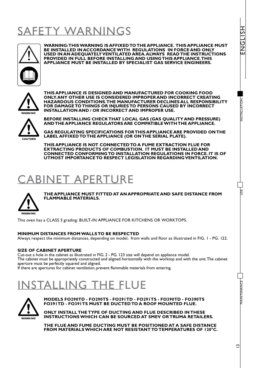
THIS APPLIANCE IS DESIGNED AND MANUFACTURED FOR COOKING FOOD ONLY.ANY OTHER USE IS CONSIDERED IMPROPER AND INCORRECT CREATING HAZARDOUS CONDITIONS.THE MANUFACTURER DECLINES ALL RESPONSIBILITY FOR DAMAGE TO THINGS OR INJURIES TO PERSONS CAUSED BY INCORRECT INSTALLATION AND / OR INCORRECT AND IMPROPER USE.
CABINET APERTURE THE APPLIANCE MUST FITTED AT AN APPROPRIATE AND SAFE DISTANCE FROM FLAMMABLE MATERIALS.
This oven has a CLASS 3 grading: BUILT-IN APPLIANCE FOR KITCHENS OR WORKTOPS.
MINIMUM DISTANCES FROM WALLS TO BE RESPECTED Always respect the minimum distances, depending on model, from walls and floor as illustrated in FIG. 1 - PG. 122.
SIZE OF CABINET APERTURE Cut-out a hole in the cabinet as ilustrated in FIG. 2 - PG. 123 size will depend on appliance model.
The cabinet must be appropriately constructed and aligned horizontally with the worktop and with the unit. The cabinet aperture must be perfectly squared and aligned.
there are apertures for cabinet ventilation, prevent flammable materials from entering.
INSTALLING THE FLUE MODELS FO290TD - FO290TS - FO291 TD - FO291TS - FO390TD - FO390TS FO391TD - FO391TS MUST BE DUCTED TO À ROOF MOUNTED FLUE.
1 Mount the flue attachment (K) and secure in place with the 2 fixture screws provided as illustrated in FIG. 3 - PG. 126 and then proceed with connecting the ducting to the flue.
The roof mounted flue must be positioned vertically with a maximum inclination of 15°. Drill a 60mm @ hole in the roof of the vehicle in proximity of the oven. To avoid damaging or denting the roof when installing the flue and 10 ensure sealing if required mount a Imm thickness metal plate to the wall with the hole.
Install the flue and from the inside of the vehicle secure in place with the nut.To guarantee the roof is sealed and does not leak, afcer the oven has been on for several hours re-tightened the flue fixture nut.
Mount and install the ducting as ilustrated in FIG. 4 - PG.127. Feed the ducting into the flue unël it stops and secure in place with a self-tapping serew.
5 Using ties secure the ducting (2 55mm) and the protective tubing (2 65mm) for their entire lengths to the walls.
GAS SUPPLY CHECK THESE SPECIFICATIONS BEFORE CONNECTING THE APPLIANCE TO THE GAS CYLINDER /BOTTLE.THE PRESSURE REGULATORS CONNECTED BETWEEN THE GAS CYLINDER AND APPLIANCE MUST CONFORM WITH THE CATEGORIES GIVEN IN THE TABLE BELOW.
This appliance is designed for running off the following types of gas at the corresponding operating pressures. The gas category (or categories) of the appliance is given on the specifications label affixed to the appliance
WHEN INSTALLING AND CONNECTING THE APPLIANCE TO THE GAS SUPPLY, ENSURE THAT THE GAS SUPPLY HOSE IS NOT TWISTED, STRETCHED OR SUBJECTED TO ANY FORM OF STRAIN WHICH COULD CREATE À HAZARD.
The gas supply pipe connected to the appliance must be à rigid metal pipe with sealed fittings. le is possible to fit a flexible hose, however, in this case the following conditions must be respected:
2) The hose can be accessed easily for inspection:
b) The hose must be protected against coming into contact with parts which heat up (for example parts underneath the burners):
©) The hose must be protected against being damaged (twisting, pulling, trapping,…);
d) The hose must be protected against being trapped by moving parts (e.g. drawers):
e) The hose must not have a length over 1.5 m:
# The hose must be replaced before its expiry date;
Once the appliance has been connected to the gas supply check for gas leaks utilising a non-corrosive fluid. Do not use à water and soap solution. NEVER USE À FLAME TO CHECK FOR GAS LEAKS.
LECTRICITY SUPPLY This chapter refers only to models with the wording 12V + on the appliance specifications label affixed to the appliance.
THIS APPLIANCE MUST BE CONNECTED TO A 12V- POWER PACK ONLY. THE CIRCUIT MUST BE FITTED WITH A SAFETY FUSE NOT HIGHER THAN 3 AMP.
WHEN WIRING THE APPLIANCE RESPECT CORRECT POLARITY!
IT IS OF UTMOST IMPORTANCE NEVER TO CONNECT THIS APPLIANCE TO MAINS VOLTAGE (230 V-) WHICH IRREVERSIBLY DAMAGES APPLIANCE COMPONENTS AND CREATES À HAZARD TO THE USER.
To connect the appliance use a 1.5 mm double red and black wire and wire to the terminal junction box located at the rear of the appliance. The red terminal is the positive pole and the black terminal is the negative pole.
CONTROLS The following symbols identify which knob corresponds to which burner. NOTE: Different models may have different knobs and different symbols.
THIS SYMBOL IS POSITIONED NEAR THE OVEN BURNER KNOB THIS SYMBOL IS POSITIONED NEAR THE GRILL BURNER KNOB The following symbols are for burner flame regulation and correspond to the position of the knob. NOTE: Different models may have different knobs and different symbols.
To ignite burner, push-in and turn the control knob to a position from 1 to 6 and maintaining the knob pushed at the same time press the electronic ignition pushbutton (for models that have x affixed to the oven door the electronic ignition button is not visible and is activated by pressing the gas knob down). Once the burner is alight maintain the Knob in this position for a few seconds to ensure the flame remains alight.
IFTHE BRUNER DOES NOT IGNITE IMMEDIATELY REPEAT IGNITION AFTER HAVING FOLLOWED EACH STEP BELOW: + PROCÉED WITH MANUAL IGNITION + CHECK THERE IS SUFFICIENT GAS INTHE GAS BOTTLE.
PÉN IF THE APPLIANCE STILL DOES NOT IGNITE SHUT OFFTHE GAS SUPPLY ATTHE MAIN GAS TAP AND CONTACT YOUR LOCAL DEALER.
- MANUAL IGNITION OVEN Manual ignition when the appliance is not fitted with the electronic ignition feature or in the event of failure in the electronic ignition.
To ignite burner, gently push-in and turn the control knob to a position from 1 to 6 and maintaining the knob pushed at the same time light the burner with a match or gas lighter. Once the burner is alight maintain the knob in this position for a few seconds to ensure the flame remains alight.
IFTHE BURNER DOES NOT IGNITE IMMEDIATELY CHECK THERE IS SUFFICIENT GAS INTHE GAS BOTTLE.
When the oven burner is ignited the flame remains at high flame in all knob positions. When the oven reaches the set temperature the flame automatically goes down to low flame.
GRILL THE GRILL BURNER MUST BE IGNITED ONLY WITH THE DOOR FULLY OPEN.
IF THE BURNER DOES NOT IGNITE IMMEDIATELY, RELEASE THE KNOB WAIT FOR AT LEAST 10 SECONDS AND IGNITE AGAIN.
AS ACCESSIBLE PARTS MAY BE VERY HOT WHEN USING THE GRILL KEEP
To ignite burner, gently push-in and turn the control knob to position GRILL or HIGH FLAME and maintaining the knob pushed at the same time press the electronic ignition button (for models with the x symbol affixed to the door, the ignition button is not visible and is activated by pressing the knob down). Once the burner is alight maintain the knob in this position for a few seconds to ensure the flame remains alight.
IF THE BRUNER DOES NOT IGNITE IMMEDIATELY REPEAT IGNITION AFTER HAVING FOLLOWED EACH STEP BELOW: + PROCEED WITH MANUAL IGNITION + CHECK THERE IS SUFFICIENT GAS IN THE GAS BOTTLE.
ATX 1FTHE APPLIANCE STILL DOES NOT IGNITE SHUT OFF THE GAS SUPPLY AT THE MAIN GAS TAP AND CONTACT YOUR LOCAL DEALER.
- MANUAL IGNITION GRILL Manual ignition when the appliance is not fitred with the electronic ignition feature or in the event of failure in the electronic ignition.
To ignite burner, gently push-in and turn the control knob to position GRILL or HIGH FLAME and maintaining the knob
pushed at the same time light the burner with a match or gas lighter. Once the burner is aligh maintain the knob in this position for a few seconds to ensure the flame remains alight.
IF THE BURNER DOES NOT IGNITE IMMEDIATELY CHECK THERE IS SUFFICIENT GAS INTHE GAS BOTTLE.
IF THE APPLIANCE STILL DOES NOT IGNITE SHUT OFF THE GAS SUPPLY AT THE une MAIN GAS TAP AND CONTACT YOUR LOCAL DEALER.
- FLAME REGULATION GRILL For models VN555 and VN565: 10 regulate flame turn the Knob to the desired cooking flame.
For all other models: the grill is to be used only at its rated thermal capacity.
VISUAL FLAME CONTROL Depending on the type of gas used the flame should be:
Propane (G31); blue flame without yellow tips. Butane (G30): flame with yellow tips when ignited which becomes more intense in colour as the burner heats.
lgnite the oven as described in the chapter OVEN. Turn the gas knob to the required position. Insert the drip tray with the spit already installed as illustrated in FIG. 7 - PG. 130. Press the spit button to turn on the spit motor.
THE ROTATING PLATE CAN BE USED WITHTHE GRILL ONLY Ii the gril burner as described in the chapcer GRILL. Position che drip &ray with the routine plate as ilustrated in IG.8 - PG. 131. Press the purpose button to turn on rotating plate motor.
OTTLES NEVER OPERATE THE APPLIANCE WITH GAS AND OR AT GAS PRESSURES DIFFERENT TO THOSE INDICATED BY SMEV AS THIS COULD CAUSE IRREGULAR AND INCORRECT OPERATION. SMEV DECLINES ALL RESPONSIBILITY FOR DAMAGE OR INJURY CAUSED BY AN INCORRECT OR IMPROPER USE OF THE Tunes APPLIANCE.
The appliance runs off standard gas bottles which can be found in the country of use. The type of gas to use is clearly marked on the packaging and on the specifications label affixed to the rear of the appliance. However always respect the following instructions: gas bottles must always be located and positioned in the compartment provided for this purpose. They must always be vertical and fitred with a pressure regulator and easily accessible and not obstructed. Do not obstruct or impede access to the gas bottle to permit quick and easy access when replacing.
WARNING!:When replacing the gas bottle always take the following precautions:
2) close all gas knobs;
b) make sure there are no flames or fires in proximiy of the gas bottle;
c) close the gas valve on the bottle to be replaced:
d) unscrew the pressure regulator on the empty bottle and remove the bottle from the purpose compartment. This procedure is inverted for fitting a new bottle. Check for gas leaks using a non-corrosive fluid/solution. Do not use a Water and soap solution. NEVER USE À FLAME TO CHECK FOR GAS LEAKS;
€) ignite the burners to check they function correcty. there are problems, call in an authorised gas service engineer.
AFTER APPLIANCE USE ALWAYS TURN OFFTHE GAS TAP ON THE BOTTLE.
GAS LEAKS We recommend the use of an electronic and homologated gas detector for checking for gas leaks. there is a smell of gas;
2) immediately open the windows and evacuate the vehicle or caravan.
b) do not turn on or of light switches or other electronic and electric appliances, do not light matches or lighters or anything that could cause the gas to ignite;
€) put out any flames
d) shut off the valve on the gas bottle or cylinder. Do not re-open this valve unless the gas leak has been identified and eliminated.
€) contact a specialised gas service engineer.
BEFORE CLEANING THE APPLIANCE ALWAYS TURN IT OFF AND DISCONNECT FROM POWER SUPPLY AND WAIT UNTIL IT HAS COOLED DOWN.
‘When removing and mounting the injectors the injector holder must be held in place with the aid of tool (FIG.9 - PG. 131).
erwenourc-W MRSTALTATIONT
VEDLIKEHOLD ET BRENNEREN MÀ KUN TENNES NÂR STEKEOVNSDSREN STÂR HELT ÂPEN.