
SRVLZPRO - PA speaker MACKIE - Free user manual and instructions
Find the device manual for free SRVLZPRO MACKIE in PDF.
| Product type | Active loudspeaker |
| Brand | MACKIE |
| Model | SRVLZPRO |
| Amplification | Class D amplifier |
| Power | 1000 W (peak) |
| Woofer | 15 inches (381 mm) |
| Tweeter | 1 inch (25 mm) compression driver |
| Frequency response | 50 Hz - 20 kHz |
| Coverage angle | 90° x 60° |
| Inputs | 2 combo XLR/Jack inputs (mic/line), 2 stereo line inputs (RCA) |
| Outputs | 1 XLR mix out |
| Controls | Volume, 2-band equalizer, compression adjustment |
| Enclosure | Molded polypropylene |
| Dimensions (W x H x D) | 680 x 430 x 380 mm |
| Weight | 18 kg |
| Power supply | 100-240 V AC, 50/60 Hz |
| Power consumption | 500 W |
| Maintenance and cleaning | Clean with a soft, dry cloth. Do not use solvents. |
| Safety | Do not open the enclosure. Use a grounded outlet. Risk of electric shock. |
| Included accessories | Power cable, user manual |
| Repairability | Spare parts available. Repair by a qualified technician. |
Frequently Asked Questions - SRVLZPRO MACKIE
User questions about SRVLZPRO MACKIE
0 question about this device. Answer the ones you know or ask your own.
Ask a new question about this device
Download the instructions for your PA speaker in PDF format for free! Find your manual SRVLZPRO - MACKIE and take your electronic device back in hand. On this page are published all the documents necessary for the use of your device. SRVLZPRO by MACKIE.
USER MANUAL SRVLZPRO MACKIE
NO USER-SERVICEABLE PARTS INSIDE
REFER SERVICING TO QUALIFIED PERSONNEL
ATTENTION: POUR EVITER LES RISQUES DE CHOC
ELECTRIQUE, NE PAS ENLEVER LE COUVERCLE. AUCUN
ENTRETIEN DE PIECES INTERIEURES PAR L'USAGER. CONFIER
L'ENTRETIEN AU PERSONNEL QUALIFIE.
AVIS: POUR EVITER LES RISQUES D'INCENDIE OU
D'ELECTROCUTION, N'EXPOSEZ PAS CET ARTICLE
A LA PLUIE OU A L'HUMIDITE
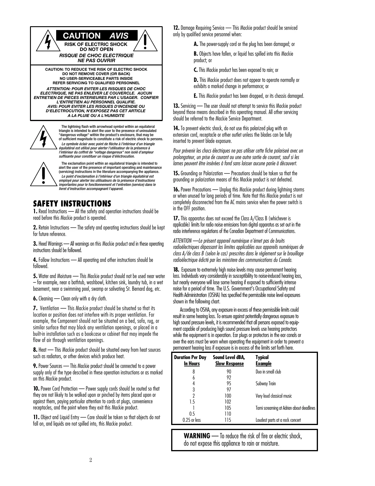
The lightning flash with arrowhead symbol within an equilateral triangle is intended to alert the user to the presence of uninsulated "dangerous voltage" within the product's enclosure, that may be of sufficient magnitude to constitute a risk of electric shock to persons.
The exclamation point within an equilateral triangle is intended to alert the user of the presence of important operating and maintenance (servicing) instructions in the literature accompanying the appliance.
- Read Instructions — All the safety and operation instructions should be read before this Mackie product is operated.
- Retain Instructions — The safety and operating instructions should be kept for future reference.
- Heed Warnings — All warnings on this Mackie product and in these operating instructions should be followed.
- Follow Instructions — All operating and other instructions should be followed.
- Water and Moisture — This Mackie product should not be used near water — for example, near a bathtub, washbowl, kitchen sink, laundry tub, in a wet basement, near a swimming pool, swamp or salivating St. Bernard dog, etc.
- Cleaning — Clean only with a dry cloth.
- Ventilation — This Mackie product should be situated so that its location or position does not interfere with its proper ventilation. For example, the Component should not be situated on a bed, sofa, rug, or similar surface that may block any ventilation openings, or placed in a built-in installation such as a bookcase or cabinet that may impede the flow of air through ventilation openings.
- Heat — This Mackie product should be situated away from heat sources such as radiators, or other devices which produce heat.
- Power Sources — This Mackie product should be connected to a power supply only of the type described in these operation instructions or as marked on this Mackie product.
- Power Cord Protection — Power supply cords should be routed so that they are not likely to be walked upon or pinched by items placed upon or against them, paying particular attention to cords at plugs, convenience receptacles, and the point where they exit this Mackie product.
-
Object and Liquid Entry — Care should be taken so that objects do not fall on, and liquids are not spilled into, this Mackie product.
-
Damage Requiring Service — This Mackie product should be serviced only by qualified service personnel when:
A. The power-supply cord or the plug has been damaged; or
B. Objects have fallen, or liquid has spilled into this Mackie product; or
C. This Mackie product has been exposed to rain; or
D. This Mackie product does not appear to operate normally or exhibits a marked change in performance; or
E. This Mackie product has been dropped, or its chassis damaged.
- Servicing — The user should not attempt to service this Mackie product beyond those means described in this operating manual. All other servicing should be referred to the Mackie Service Department.
- To prevent electric shock, do not use this polarized plug with an extension cord, receptacle or other outlet unless the blades can be fully inserted to prevent blade exposure.
Pour prévenir les chocs électriques ne pas utiliser cette fiche polarisé avec un prolongateur, un prise de courant ou une autre sortie de courant, sauf si les lames peuvent être insérées à fond sans laisser aucune partie à découvert. - Grounding or Polarization — Precautions should be taken so that the grounding or polarization means of this Mackie product is not defeated.
- Power Precautions — Unplug this Mackie product during lightning storms or when unused for long periods of time. Note that this Mackie product is not completely disconnected from the AC mains service when the power switch is in the OFF position.
- This apparatus does not exceed the Class A/Class B (whichever is applicable) limits for radio noise emissions from digital apparatus as set out in the radio interference regulations of the Canadian Department of Communications.
ATTENTION —Le present appeareil numérique n'émet pas de bruits radioélectriques dépassant les limites applicables aux appeareils numériques de class A/de class B (selon le cas) prescrites dans le règlement sur le brouillage radioélectrique édité par les ministère des communications du Canada. - Exposure to extremely high noise levels may cause permanent hearing loss. Individuals vary considerably in susceptibility to noise-induced hearing loss, but nearly everyone will lose some hearing if exposed to sufficiently intense noise for a period of time. The U.S. Government's Occupational Safety and Health Administration (OSHA) has specified the permissible noise level exposures shown in the following chart.
According to OSHA, any exposure in excess of these permissible limits could result in some hearing loss. To ensure against potentially dangerous exposure to high sound pressure levels, it is recommended that all persons exposed to equipment capable of producing high sound pressure levels use hearing protectors while the equipment is in operation. Ear plugs or protectors in the ear canals or over the ears must be worn when operating the equipment in order to prevent a permanent hearing loss if exposure is in excess of the limits set forth here.
| Duration Per Day In Hours | Sound Level dBA, Slow Response | Typical Example |
| 8 | 90 | Duo in small club |
| 6 | 92 | |
| 4 | 95 | Subway Train |
| 3 | 97 | |
| 2 | 100 | Very loud classical music |
| 1.5 | 102 | |
| 1 | 105 | Tami screaming at Adrian about deadlines |
| 0.5 | 110 | |
| 0.25 or less | 115 | Loudest parts at a rock concert |
WARNING — To reduce the risk of fire or electric shock, do not expose this appliance to rain or moisture.
Thank you for choosing a Mackie professional sound reinforcement mixer! The 24-4-VLZ PRO and 32-4-VLZ PRO are equipped with our new precision-engineered XDR™ Extended Dynamic Range premium studio-grade mic preamps, featuring:
Full gain range from 0 to 60dB
- Massive +22dBu line signal handling capability
130dB dynamic range
Distortion and noise: 0.0007% , 20Hz to 20kHz
- Bullet-proof RF rejection using a DC pulse transformer
192kHz bandwidth
These live sound mixers are designed to meet the needs of almost any venue: indoor concert, club or theatre, meeting room, sanctuary, outdoor gathering, as well as a recording studio.
Here's a quick glance at all the features you've acquired:
20 mono channels (24-4-VLZ PRO) or 28 mono channels (32-4-VLZ PRO) with:
- Mackie's cutting-edge XDR™ microphone preamps
- Variable input trim (0 to +60dB mic, -15 to +45dB line)
- Phantom power (globally switched)
- Switchable 75Hz low cut filter
- TRS insert jack
- 2 pre-fader aux sends
- 2 switchable pre or post-fader aux sends
- 2 post-fader aux sends
3-band mid-sweep EQ
Pan, mute, and 1-2/3-4/L-R busing - PFL or AFL solo
- 60mm mono fader
2 stereo line channels, with:
- 20dB to +20dB variable input trim
- 2 pre-fader aux sends
- 2 switchable pre or post-fader aux sends
- 2 post-fader aux sends
4-band EQ
Pan, mute, and 1-2/3-4/L-R busing - PFL or AFL solo
- 60mm stereo fader
Comprehensive master section, with:
- 60mm subgroup mono faders
- Assign-to-main switching for each subgroup
- "Air" EQ for each subgroup
- PFL or AFL solo for each subgroup
- 60mm main mix stereo fader
- TRS insert jacks for main mix
Balanced XLR and TRS stereo main outs - XLR mono output with level control
13-segment stereo LED metering - Mackie's (in)famous Rude Solo Light
- 6 aux send masters with level controls
- 4 stereo aux returns with level controls
- 2 effects to monitor controls
- RCA tape in & out
- Tape to Main Mix break switch
- XLR input for talkback microphone
- 2 headphone outputs with level control
Control room output with level control
12VBNClampsocket
At Mackie, we know what it takes to make roadworthy gear. After all, our mixers have traveled all over the world under the worst of conditions. We've applied these experiences to the mechanical design of the 24-4-VLZ PRO and 32-4-VLZ PRO mixers.
Live sound only? No way! Although both mixers are aimed primarily at sound reinforcement, they have features such as 4-bus, metering and control room circuitry, that make them serve easily as recording or mixing consoles.
Please write your serial number here for future reference (i.e., insurance claims, tech support, return authorization, etc.):
Serial Number
Purchased at:
Date of purchase:
Make sure that you keep your proof of purchase in a safe place, otherwise it will end up in the land of enchantment, where TV remotes, car keys and odd socks go.
ABOUT THIS MANUAL
The stuff you MUST read:
First, you must read and follow all the safety instructions on page 2.
Before you get to work, please read the "Quick Start" section on page 6. It's a list of steps that will familiarize you with the mixer and help you set up a basic performance. The rest of the manual explains the mixer's features in excruciating detail.
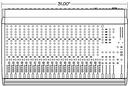
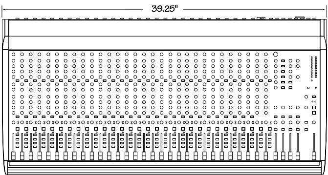
24-4-VLZ PRO and 32-4-VLZ PRO
This manual covers both mixers. The 32-4-VLZ PRO has eight more mic/line channel strips, otherwise the two models are identical.
About all those numbers:
Every feature on the mixer has a number assigned to it. Whenever a feature is illustrated described or mentioned, its number will be right next to it. They'll help you find your way around this whopping opus, and we opus you will like it.
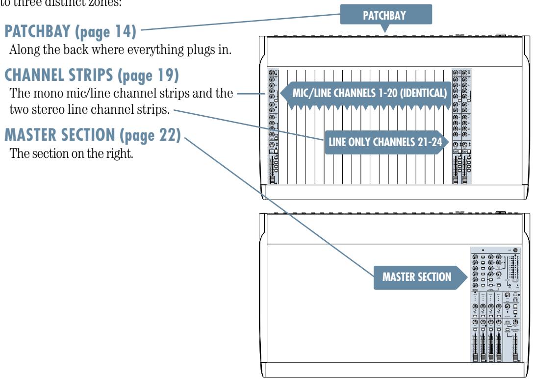
Every feature of the mixer is described "geographically;" in other words, in order of where it is physically placed on the mixer's top or rear panel. These descriptions are divided into three chapters, just as your mixer is organized into three distinct zones:
Further information:

This icon marks information that is critically important or unique to your mixer. For your own good, read and remember them.

This icon will lead you to in-depth explanations of features and practical tips. While not mandatory, they usually have some valuable nuggets of information.
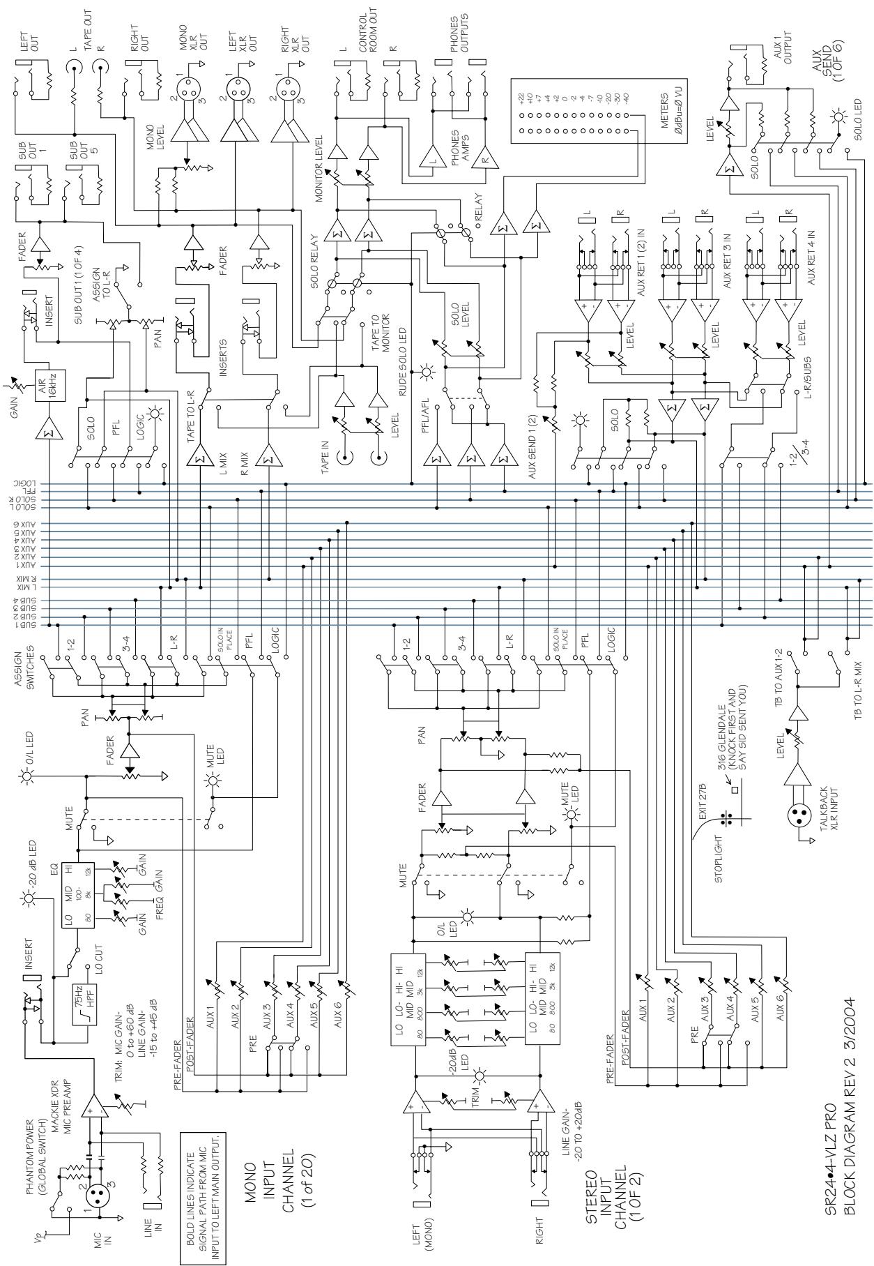
This entire manual is condensed onto one page, albeit in hieroglyphics: see the Block Diagram on page 28.
Please come on by and visit our website, at http://www.mackie.com. It contains helpful stuff about mixers and audio, as well as specific information about this and other Mackie products.
CONTENTS
page
SAFETY INSTRUCTIONS 2
INTRODUCTION 3
ABOUT THIS MANUAL 4
QUICK START 6
APPLICATIONS DIAGRAMS 9
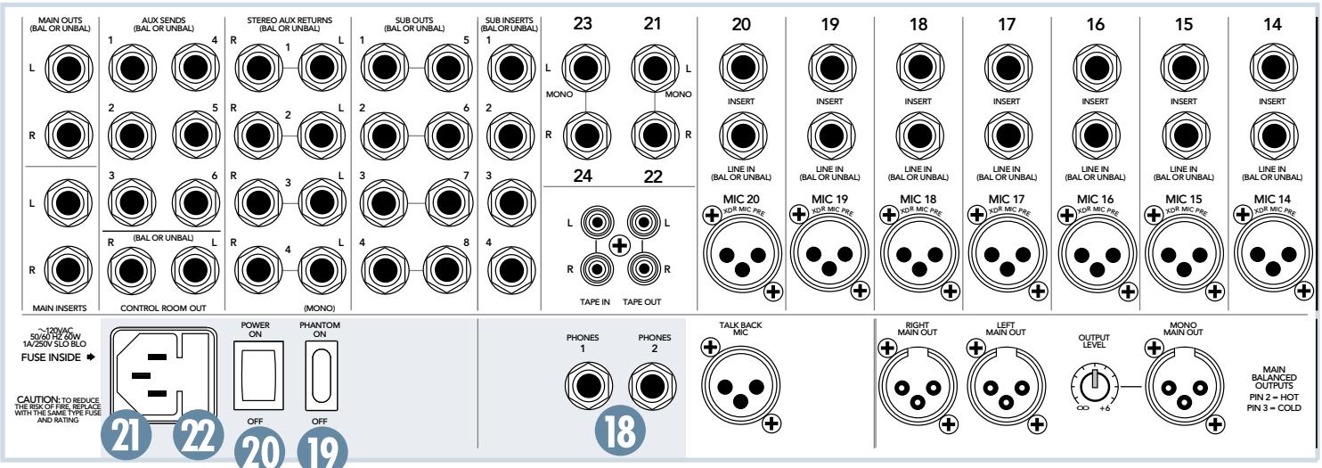
PATCHBAY FEATURES
MIC 14
LINE IN 14
INSERT 15 EFFECTS: SERIAL OR PARALLEL? 15
STEREO LINE IN 15
TAPE OUT 16
6 TAPE IN 16
7 SUB INSERTS 16
SUB OUTS 16 DOUBLE BUSING 16
STEREO AUX RETURNS 17
10 AUX SENDS 17
1 CONTROL ROOM OUT 17
12 MAIN OUTS (TRS) 17
13 MAIN INSERTS 17
14 MONO MAIN OUT 17
OUTPUT LEVEL 17
16 MAIN OUT (XLR) 17
17 TALKBACK MIC 17
18 PHONES 18
19 PHANTOM SWITCH 18
20 POWER SWITCH 18
24 AC RECEPTACLE 18
FUSE 18
CHANNEL STRIP FEATURES
TRIM 19
AUX SEND
26AUX 19
PRE 19
EQ SECTION
28 HI 20
9 MID 20
FREQ 20
3 HI MID 20
LOW MID 20
33 LOW 20
34 LOW CUT 20
35 OL LED 21
36 -20 LED 21
37 PAN 21
38 MUTE 21
39 SOLO 21
40 1-2 & 3-4. 21
④ L-R 21
42 CHANNEL FADER 21
page
MASTER SECTION FEATURES
45 LAMP CONNECTOR 22
AUX SEND MASTER
46 AUX SEND MASTERS 22
47 SOLO 22
STEREO AUX RETURNS
STEREO AUX RETURNS 23
49 TO AUX SEND 1-2 23
50 ASSIGN TO SUB 23
SUB 23
SOLO 23
TAPE RETURN 23
54 METERS 23
ZERO EQUALS ZERO 23
POWERLED 23
SUBGROUPS
AIR 24
SOLO 24
5 PAN 24
59 L/R ASSIGN 24
SUBGROUP FADERS 25
SOLO
RUDE SOLO LIGHT 25
LEVEL 25
MODE 25
64 AUX LED 25
SUBLED 25
TALKBACK
LEVEL 25
6 MAIN MIX 25
AUX 1-2 25
69 TAPE RETURN TO PHONES/C-R 25
70 PHONES/C-R LEVEL 26
71 TAPE RETURN TO MAIN MIX 26
72 MAIN MIX FADER 26
SPECIFICATIONS 27
BLOCK DIAGRAM 28
GAIN PATH 29
SERVICE INFORMATION 30
SR24*4/SR32*4 LIMITED WARRANTY. 31
QUICK START
ZERO THE CONSOLE
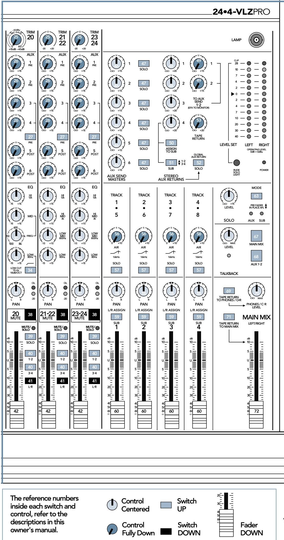
Note: the numbers in brackets refer to the numbers inside each switch and control in the drawing on the next page.
- On the rear panel, turn the POWER switch and the PHANTOM off, and the OUTPUT LEVEL fully down.

- Disengage these switches (for pushbutton switches, "disengaged" or "off" refers to the "up" position):
PRE (27)
LOW CUT (34)
SOLO (39)
1-2 & 3-4 (40)
SOLO (47)
ASSIGN TO SUB (50)
SUB (51)
SOLO (52)
SOLO (57)
L/R ASSIGN (59)
MODE (63)
MAIN MIX (67)
AUX 1-2 (68)
TAPE RETURN TO PHONES/C-R (69)
TAPE RETURN TO MAIN MIX (71)

- Engage these switches (for pushbutton switches, "engaged" or "on" refers to the "down" position):
MUTE (38)
L-R (41)
When we say engaged, this does not imply that you should become betrothed in any legally binding sense, although there is probably some drive-in wedding chapel in Vegas, where this can be arranged.

Control Fully Down
- Set these controls fully down (for rotary controls, "down" refers to the fully counter-clockwise position; for faders, it refers to all the way down):
TRIM (25)
AUX (26)
TO AUX SEND 1-2 (49)
TAPE RETURN (53)
AIR (56)
CHANNEL FADER (42)
SUBGROUP FADER (60)
MAIN MIX FADER (72)


- Set these controls at unity (for rotary controls, "unity" refers to the center detent position.
HI (28)
MID (29)
FREQ (30)
HI MID (31)
LOW MID (32)
LOW (33)
PAN (37)
AUXSENDMASTERS(46)
STEREO AUX RETURNS (48)
PAN (58)
SOLO LEVEL (62)
TALKBACK LEVEL (66)
PHONES/C-R LEVEL (70)
Power Off
Phantom Off
Output Level Fully Down
MAKE THE CONNECTIONS:
- Make sure your amplifiers are turned off before making any connections.
- Connect speakers to your amplifier's outputs (unless, of course, you have powered speakers, such as the Mackie SRM 450 active monitors).
- Plug all the sound system components into suitable AC outlets; properly grounded and capable of delivering adequate current. Use power strips to minimize ground loops.
- Using TRS or XLR cables, make connections from the mixer's MAIN OUTS (12), (16) to your amplification system's line inputs.
- Make connections from your microphones and instruments to the mixer: Connect balanced microphones to the mono channel MIC (1) jacks. (For condenser microphones, engage the PHANTOM (19) switch.) Connect line-level instruments (synthesizers, guitar effects devices, direct boxes) to the mono or stereo channel LINE IN (2) (4) TRS jacks.
- Follow the procedure shown on page 6 to zero the console. This will also MUTE (38) each channel.
- Turn on all the AC power switches, including the mixer and all other equipment. Leave the amplifier's power switch for last. This prevents power-up thumps which can damage speakers.
- Turn up the MAIN MIX FADER (72) to the "U" label. You should hear nothing at this point.
SET THE LEVELS:
- Choose one of the microphones or instruments you've connected. Make some noise. If it's a microphone, speak at your normal singing volume. If it's a synthesizer, play it at its normal output level.
- While making noise, engage that channel's SOLO (39) switch.
- Turn up that channel's TRIM (25) up until the METERS (54) peak near the "0" label.
- Disengage that channel's MUTE (38).
-
Turn up the CHANNEL FADER (42) to the unity gain ("U" label). You should now be hearing your noise in the phones or control room (70).
-
If necessary, apply channel EQ (28-34) changes. Resultant level changes can be corrected by readjusting the TRIM (25).
- Disengage that channel's SOLO (39) switch.
- Repeat steps 1 through 7 for the remaining active channels.
- Stop making noise, start making music.
TWEAK THE MIX:
- Engage MUTE (38) on all channels except your rhythm section (drums & bass).
- Adjust the rhythm section's channel PANs (37) and CHANNEL FADERs (42) to get a good balance of levels.
- Un-mute the other active channels and adjust their pans and faders.
- Tweak the fader, pan and EQ controls. Fine tune your mix. Walk the room to see how it sounds away from the mixer. Keep tweaking.
- Consider applying the proper EQ adjustments by cutting certain frequencies, rather than boosting. Compensate for EQ cut by a slight boost in volume. For live sound applications, this technique allows for more gain before feedback, and gives improved system reliability.
KNOW THESE THINGS:

- Never listen to loud music for prolonged periods. See the safety instructions on page 2.
- Never plug amplifier
outputs into anything except speakers.
- Never use guitar cables to connect amplifiers to speakers.
- Before making connections to an amp or reconfiguring an amp's routing, turn the amp's power off, make the changes and then turn the power back on.
- When you shut down your equipment, turn off all the amplifiers first. When powering up, turn on the amplifiers last. This prevents power-up and power-down thumps which can damage speakers.
- Save the shipping box and packing material. You may need them someday.
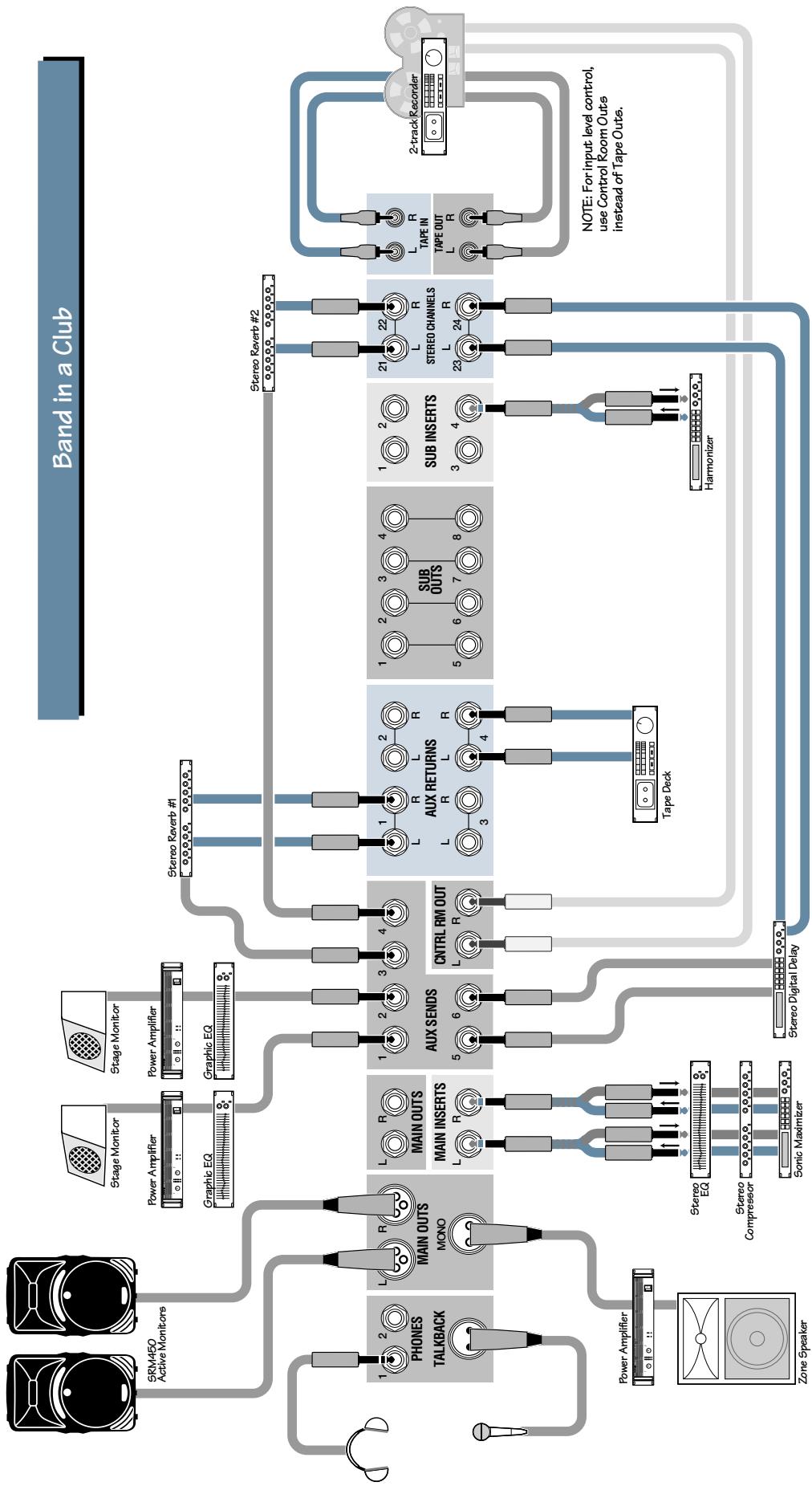
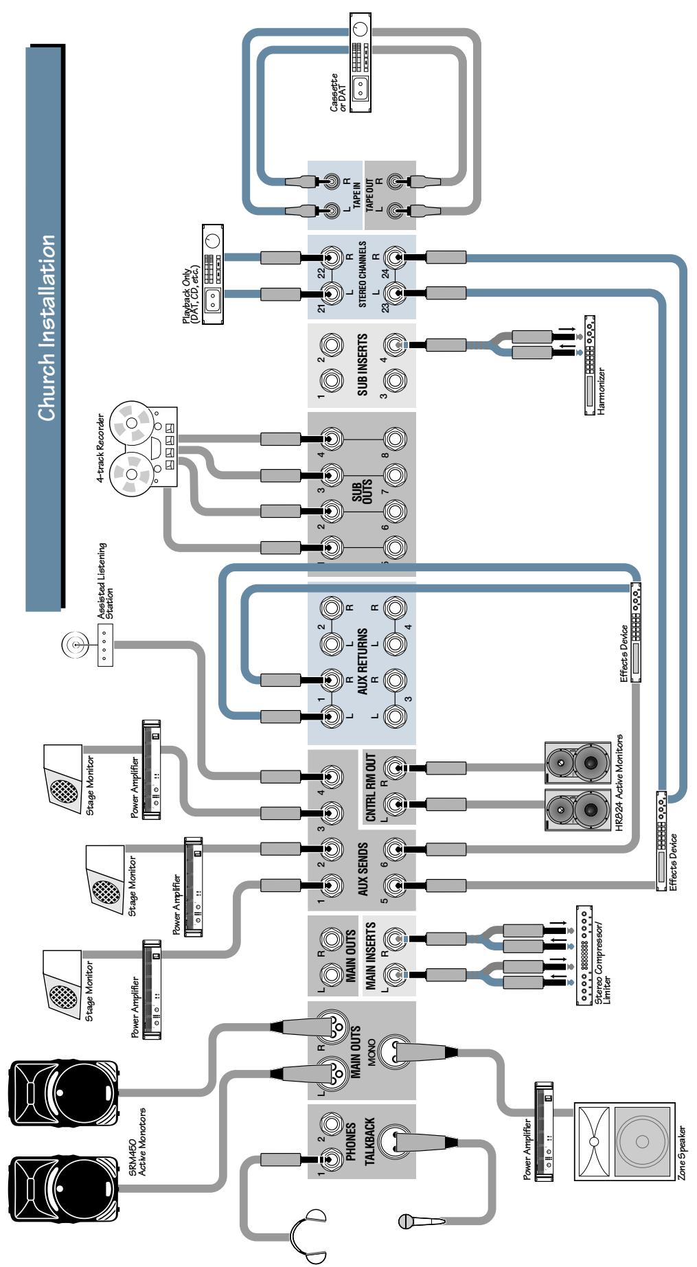
APPLICATION DIAGRAMS
| ch. | device | input | insert | assignment |
| 1 | kick | mic | gate | submix 1 |
| 2 | snare | mic | gate | submix 1 |
| 3 | hi hat | mic | submix 1 | |
| 4 | tom 1 | mic | gate | submix 1 |
| 5 | tom 2 | mic | gate | submix 1 |
| 6 | tom 3 | mic | submix 1 | |
| 7 | drum overhead mic L | mic | submix 1 | |
| 8 | drum overhead mic R | mic | compressor | submix 1 |
| ch. | device | input | insert | assignment |
| 1 | kick | mic | all optional | submix 1-2 |
| 2 | snare | mic | submix 1-2 | |
| 3 | drum overhead mic L | mic | submix 1-2 | |
| 4 | drum overhead mic R | mic | submix 1-2 | |
| 5 | bass direct | line | submix 1-2 | |
| 6 | guitar mic | mic | submix 1-2 | |
| 7 | piano PZM mic | mic | submix 1-2 | |
| 8 | synth direct | line | submix 1-2 |
| ch. | device | input | insert | assignment | ch. | device | input | insert | assignment |
| 1 | kick | mic | gate | submix 1-2 | 8 | bass | mic | EQ | submix 4 |
| 2 | snare | mic | gate | submix 1-2 | 9 | bass direct | line | compressor | submix 4 |
| 3 | hi hat | mic | submix 1-2 | 10 | guitar close mic | mic | gate | aux 6 or dir. | |
| 4 | hi tom | mic | gate | submix 1-2 | 11 | guitar distant mic | mic | gate | L/R bus |
| 5 | lo tom | mic | gate | submix 1-2 | 12 | scratch vocal | mic | L/R bus | |
| 6 | drum overhead mic L | mic | submix 3 | 13 | digital multitrack 1 | line | L/R bus | ||
| 7 | drum overhead mic R | mic | submix 3 | 14 | digital multitrack 2 | line | L/R bus | ||
| ch. | device | input insert | assignment |
| 1 | talk back mic | mic | |
| 2 | from splitter snake | line | |
| 3 | from splitter snake | line | |
| 4 | from splitter snake | line | |
| 5 | from splitter snake | line | |
| 6 | from splitter snake | line | |
| 7 | from splitter snake | line |
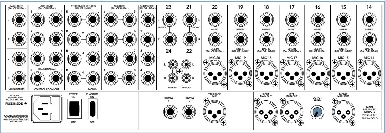
PATCHBAY
This is where everything gets plugged in: microphones, line-level instruments, effects devices, headphones and the ultimate destination(s): PA system, tape recorder, etc.
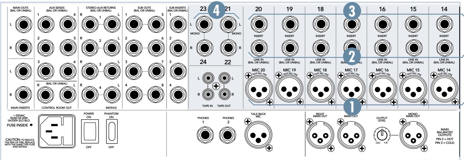
1. MIC
The mono channels are equipped with Mackie's cutting-edge XDR™ microphone preamplifiers; providing up to 60dB of rugged, low-noise, crystal-clear, phantom-powered amplification. Their balanced circuitry rejects all manner of extraneous interference. Professional condenser, dynamic and ribbon mics will all sound excellent through these XLR inputs.
The inputs will accept almost any kind of balanced mic that has a standard XLR-type male mic connector.
XLR balanced wiring:
Pin 1 = shield
Pin 2 = hot (+)
Pin 3 = cold (-)
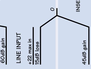
2. LINE IN
The line inputs share circuitry (but not phantom power) with the mic preamps, and can be driven by balanced or unbalanced sources. These inputs can accept virtually any line-level signal, from -45dB up to +20dB.
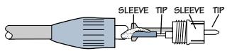
1/4" TS (Tip-Sleeve) unbalanced wiring:
Tip = hot(+)
Sleeve = shield
1/4" TRS (Tip-Ring-Sleeve) balanced wiring:
Tip = hot(+)
Ring = cold(-)
Sleeve = shield
3. INSERT
With nothing plugged into this jack, the channel's signal goes straight through the mic/ line preamp to the channel strip. With an external effects device plugged into this jack, the channel's signal leaves the mixer, goes through the effects device and back into the channel strip.
Use these jacks to send the channel signal through a compressor, graphic equalizer or similar device. Since the insert is before the CHANNEL FADER (42), moving that fader will not alter the level sent to a compressor, thereby preserving the original signal's characteristics.
These unbalanced jacks are wired thusly:
Tip = Send (to effects device input)
Ring = Return (from effects device output)
Sleeve = Common ground (connect shield to all three sleeves)
Specialty "Y" cables, developed just for these jacks, are widely available.
Besides being used for inserting effects devices, these jacks can also be used as channel direct outputs; post-TRIM, pre-LOW CUT and pre EQ.
Here are three ways to use the INSERTJacks:
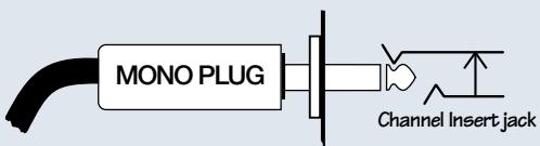
Direct out with no signal interruption to master. Insert only to first "click"
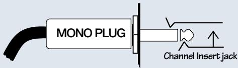
Direct out with signal interruption to master. Insert all the way in to the second "click"
For use as an effects loop.
(TIP = SEND to effect, RING = RETURN from effects)
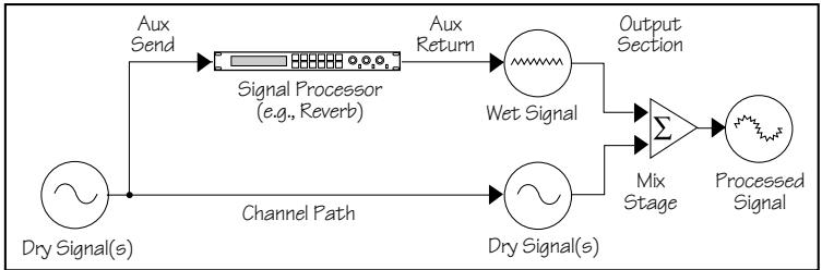
EFFECTS: SERIAL OR PARALLEL?

Effects devices are used either in serial or in parallel:
Serial means that the entire signal is routed through the effects device. Examples include: preamps, compres
sor/limiters, graphic equalizers. Connections are typically made via the channel insert jacks.
Parallel means that a portion of the signal is tapped off to the effects device processed and returned, to be mixed with the original "dry" signals. Multiple signals (via multiple mixer channels) can all make use of the same parallel effects device. Examples include: reverb, delay, chorus. Connections are typically made via aux sends & aux returns.
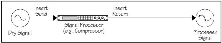
Serial Device
Parallel Device
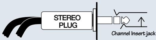
4. STEREOLINE IN
These balanced inputs are designed for TRS balanced or TS unbalanced signals, from -20dB to +20dB. They can accept any line-level instrument, effects device or tape player.
When connecting a stereo device (two cords), use the LEFT (MONO) input and the RIGHT input.
When connecting a mono device (just one cord), always use the LEFT (MONO) input and plug nothing into the RIGHT input. A trick called "jack normaling" will cause the signal to appear on both sides.
These inputs accept 1/4 TRS balanced and 1/4 TS unbalanced plugs, see the previous page for wiring details.
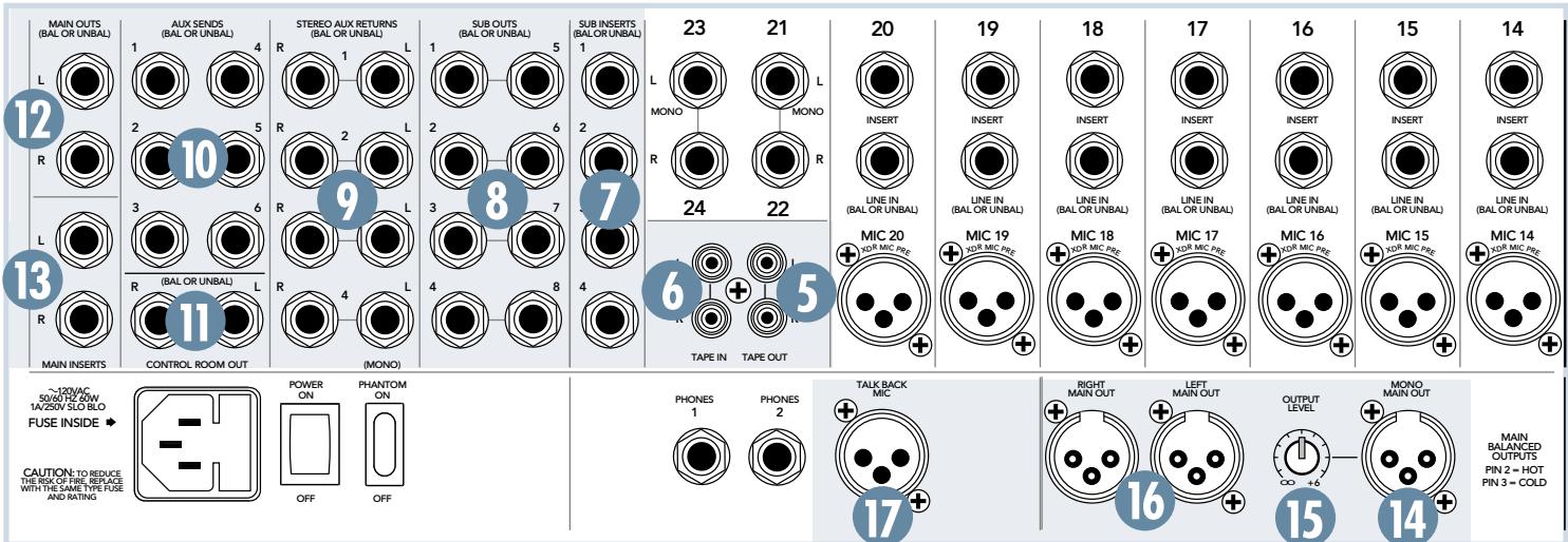
5. TAPE OUT
Use these stereo jacks to capture the entire performance to tape. The signal at these jacks is the main mix, post-MAIN INSERTS (13) and post-MAIN MIX FADER (72). Signals at these jacks will depend on the levels set by the main mix fader.
RCA unbalanced wiring:
Tip = hot, sleeve = shield
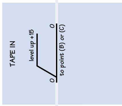
6. TAPE IN
Patch the outputs of an intermission entertainment device here. Any line level mono or stereo device can be used: tape, CD player, television audio, etc. See TAPE RETURN TO PHONES/C-R (69) and TAPE RETURN TO MAIN MIX (71) for more information.
When connecting a mono device (just one cord), use a "Y-splitter" RCA adapter. It turns a mono cord into two cords; so both the left and right tape input jacks can be patched. This adapter is widely available.
7. SUB INSERTS
With nothing plugged into these jacks, the subgroup mix goes straight through the SUBGROUP FADER (60) to the SUB OUTS (8). With an effects device plugged into these jacks the subgroup mix leaves the mixer, goes through the effects device and back into the mixer's subgroup faders.
Use these jacks to send a subgroup mix through a compressor, graphic equalizer or similar device. Since the insert is before the subgroup faders, moving the fader will not
alter the level sent to a compressor, thereby preserving the original signal's characteristics.
These unbalanced insert jacks are wired exactly the same as shown for INSERT (3) on page 15.
8. SUB OUTS
In live sound applications, these jacks can be patched into secondary amplifiers, allowing levels to be controlled, independently of the main mix, via the SUBGROUP FADERs (60).
Alternatively, the MAIN OUTS (12) (16) could feed the amplifiers while the subgroups feed a recorder.
In studio applications, these outputs can be used as four separate paths to feed four or more tracks of a multi-track recorder.
See 1-2 & 3-4 (40) and L/R ASSIGN (59) for more information.
Accepts 1/4 "TRS balanced or 1/4 "TS unbalanced plugs, see page 14 for wiring details.
DOUBLE BUSING
Although this is a "four-bus mixer," meaning there are four separate subgroups available, it can be used to feed all eight tracks of a multitrack recorder, thanks to a trick called Double Busing.
SUB OUTS 1 and 5 carry the same signal, and so do 2 and 6, 3 and 7, 4 and 8. Patch these outputs into the corresponding inputs of your multi-track recorder.
To record onto track 1, for example, put track 1 in record mode, but leave track 5 in safe mode. To record onto track 5, put track 5 in record and put track 1 in safe mode.
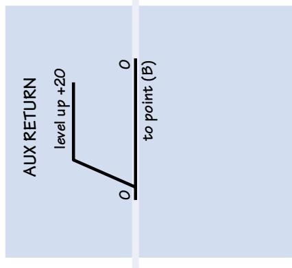
9. STEREO AUX RETURNS
Patch the outputs of external parallel effects devices (reverb, delay, etc.) to these inputs.
When connecting a mono device (just one cord), always use the LEFT (MONO) input and plug nothing into the RIGHT input. A trick called "jack normaling" will cause the signal to appear on both sides.
Accepts 1/4" TRS balanced or 1/4" TS unbalanced plugs, see page 14 for wiring details.
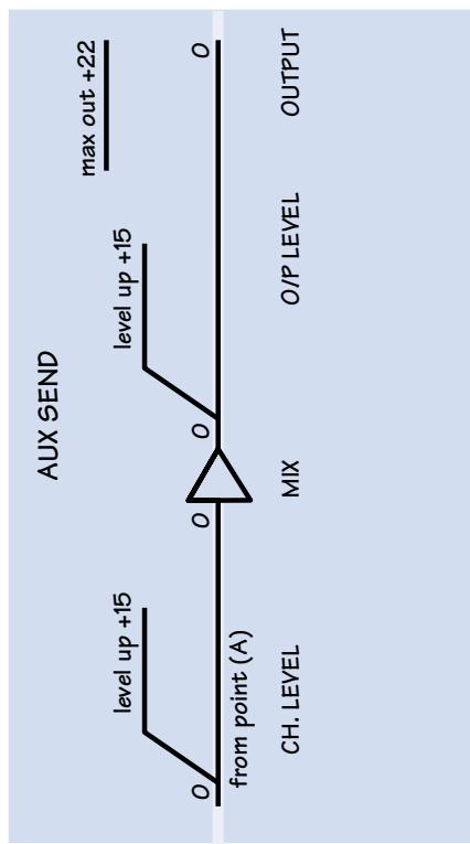
10. AUX SENDS
With aux sends in "pre" mode, patch these jacks into stage monitor amplifier inputs. With aux sends in "post" mode, patch these jacks into the inputs of an effects device. See AUX (26) and PRE (27) for more information.
Accepts 1/4 TRS balanced or 1/4 TS unbalanced plugs, see page 14 for wiring details.
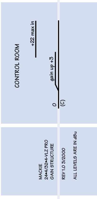
11. CONTROL ROOM OUT
These line-level jacks are used to feed amplifier inputs in a control room situation, typically found in a recording studio.
The stereo signal at these jacks is the same as the MAIN OUTS (12) (16), except when any SOLO (39) (47) (52) (57) or the TAPE RETURN TO PHONES/C-R (69) is engaged. Its level is independently controlled by PHONES/ C-R LEVEL (70).
Accepts 1/4" TRS balanced or 1/4" TS unbalanced plugs, see page 14 for wiring details.
12. MAIN OUTS (TRS) and 16. MAIN OUT (XLR)
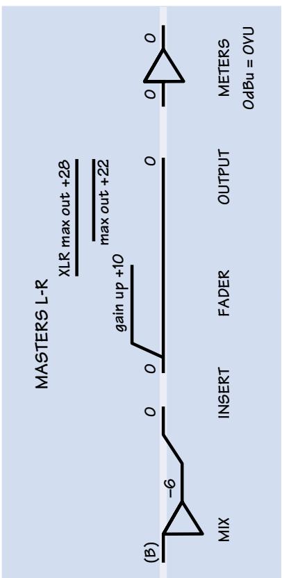
Available in two types, XLR and TRS, the main output represents the end of the signal path, just after the MAIN MIX FADER (72), where the fully mixed stereo signal enters the real world.
The XLR balanced outputs will add 6dB when connected to balanced inputs, thereby elevating signal from the noise floor by that amount.
The TRS balanced outputs offer the advantage of having no 6dB level change to deal with, while still providing extraneous noise rejection. These accept 1/4 TRS balanced or 1/4 TS unbalanced plugs, see page 14 for wiring details.
13. MAIN INSERTS
With nothing plugged into these jacks, the main mix goes straight through the MAIN MIX FADER (72) to the MAIN OUTS (12) (16). With an effects device plugged into these jacks, the main mix leaves the mixer, goes through the effects device and back into the mixer's main mix faders.
Use these jacks to send the main mix through a compressor, graphic equalizer or similar device. Since the insert is before the main mix fader, moving the fader will not alter the level sent to a compressor, thereby preserving the signal's characteristics.
These unbalanced insert jacks are wired exactly the same as shown for INSERT (3) on page 15.
14. MONO MAIN OUT
The signal sent out of this XLR jack is a sum of the left and right signals at the MAIN OUTS (12) (16). It can be used to feed a mono sound system or a mono recording device. See OUTPUT LEVEL (15) for more information.
This XLR balanced output will add 6dB when connected to a balanced input, thereby elevating signal from the noise floor by that amount.
Accepts XLR balanced plugs, see page 14.
15. OUTPUT LEVEL
Use this knob to independently set the level of the MONO MAIN OUT (14). The level is also dependent on the level set by the MAIN MIX FADER (72). Unity gain is at 3 o'clock, and there is 6dB additional gain available when turned fully up.
To feed a microphone input, like that found on a camcorder, turn this knob down to the 9:00 range. Use the device's input meters to assure a good level.
17. TALKBACK MIC
Connect a balanced dynamic microphone to this XLR jack to utilize the mixer's talkback feature (66) (67) (68). This input does not provide phantom power, so it cannot accept condenser microphones.
Accepts XLR balanced plugs, see page 14.
18. PHONES
The stereo signal from each of these identical outputs is a high-current version of the signal from CONTROL ROOM OUT (11). Connect TRS headphones to either or both jacks.
The stereo signal at these jacks is the same as the MAIN OUTS (12) (16), except when SOLO (39) or TAPE RETURN TO PHONES/C-R (69) is engaged. Its level is independently controlled by PHONES/C-R LEVEL (70).
TRS stereo wiring:
Tip = left, ring = right, sleeve = shield
19. PHANTOM
Engage this switch to provide phantom power to all the MIC (1) input jacks. All of the XLR mic inputs, except TALKBACK MIC (17), are capable of simultaneously providing phantom power. Phantom power is required to operate most condenser microphones (some condenser microphones are battery-powered). +48VDC phantom power is delivered to pins 2 and 3 of the XLR connectors.
For dynamic, ribbon or tube mics that do not require phantom power, leave this switch off. If both condenser and dynamic mics are used, turn the switch on. Phantom power will not hurt most dynamic mics. If unsure, check the microphone's user manual.
Caution: Turn all output levels down before operating this switch to avoid the possibility of a "pop" in the speakers.
Caution: Connecting an external line-level device to an XLR input connector with the phantom power activated could damage that device. Use the LINE IN (2) or STEREO LINE IN (4) jacks for connecting line-level signals.
20. POWER
The POWER switch is located on the rear panel, adjacent to the AC RECEPTACLE (21). Push in the top side of the switch to turn on, this connects the mixer to main AC power. The POWER (55) LED in the top right corner of the console, will glow in confirmation.
To turn the mixer off, push the switch the other way. Note: turning off the switch does not remove all power from the mixer. To remove all power, the power cord must be disconnected from the power source.
21. AC RECEPTACLE
Connect the supplied AC linecord into this IEC socket to provide AC power to the Mixer. Plug the cord into a suitable AC outlet; properly grounded and capable of delivering adequate current.
Replacement AC linecords are widely available at any office or computer supply store.
22. FUSE INSIDE
An AC power fuse is located in a tiny slideout compartment inside the AC RECEPTACLE (21). It's a good idea to carry spare fuses.

Always remove the power cord before changing the fuse.
Always use the correctly rated fuse for your specific mixer:
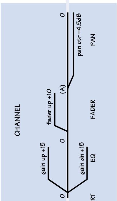
The channel strip is where you dress up each channel's audio: setting the gain, adding EQ, riding the fader, tapping signal off to stage monitors and effects devices. After a signal leaves the channel strip it goes through a mix stage and on to the master section (page 22).
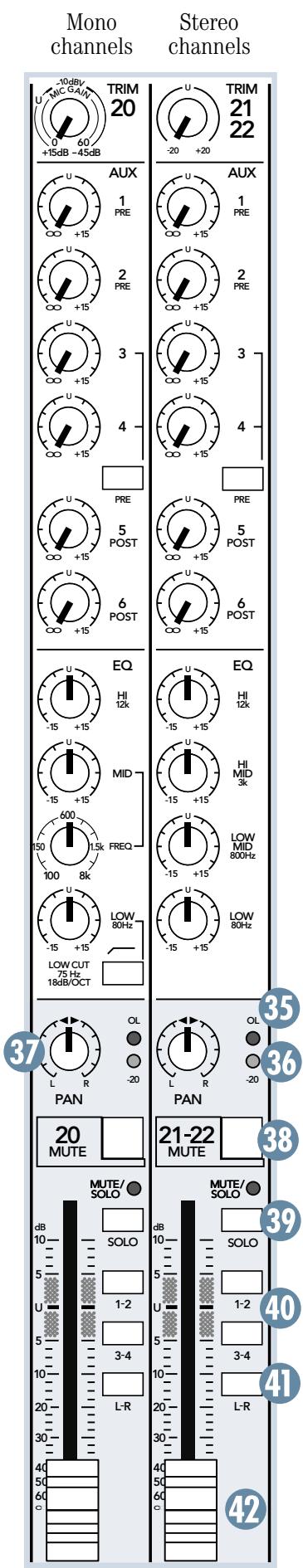
The 24-4-VLZ PRO has 20 mono channels and two stereo channels. The 32-4-VLZ PRO has 28 mono channels and two stereo channels. All of the mono channels are identical, and all of the stereo channels are identical. In this chapter, both flavors are described with the help of an illustration from the 24-4-VLZ PRO. This shows a mono channel strip 20 and its neighbor, the stereo strip 21/22.
25. TRIM
If you haven't already, please read SET THE LEVELS on page 8.
TRIM adjusts the input sensitivity of the mic and line inputs connected to the channels, mono or stereo. This allows signals from the outside world to be adjusted to optimal internal operating levels.
Through a mono channel's MIC (1) XLR input, there is 0dB of gain fully down and 60dB of gain fully up.
Through a mono channel's LINE IN (2) TRS input, there is 15dB of attenuation fully down and 45dB of gain fully up; with a "U" (unity gain) label at about 10:00 (knob one-third up).
Through the stereo channel's STEREO LINE IN (4) TRS inputs, there is 20dB of attenuation fully down and 20dB of gain fully up; with a "U" (unity gain) label at 12:00 (knob halfway up).
AUX SEND: (26 and 27)
26. AUX
These knobs tap a portion of each channel signal and send it out, via the AUX SENDS (10) jacks, to an amp & speakers for stage monitors or to an effects device for parallel effects processing.
Each AUX knob's level ranges from off, through unity (center detent position), on up to 15dB of extra gain (fully clockwise). AUX levels are controlled by these knobs and by the AUX SEND MASTERS (46).
The stereo channels' AUX knobs control a mono sum of the channel's stereo signals. For instance, channel 21 (L) and 22 (R) mix together to feed that channel's mono AUX send knobs.
27. PRE
Aux sends 1 & 2 are always pre-fader, designed for stage monitor applications. Aux sends 5 & 6 are always post-fader, designed for parallel effects applications. Aux sends 3 & 4, thanks to this switch, can be set to be pre- or post-fader, so they can be used for monitors or effects.
PRE-FADER: With the PRE switch engaged (down), AUX 3 and 4 deliver signals post-insert, post-low cut, post EQ, post-mute, and pre-fader. Any changes made to the channel controls, except the fader, will affect the aux send signal.
POST-FADER: With the PRE switch disengaged (up), AUX 3 and 4 deliver signals post-insert, post-low cut, post-mute, post-EQ and post-fader. Any changes made to the channel controls will affect the aux send signal.
EQ: (28 through 34)
The mixer has low shelving, mid peaking and high shelving EQ. "Shelving" means that the circuitry boosts or cuts all frequencies past the specified frequency. For example, boosting the LOW EQ knob boosts bass frequencies at 80Hz and below. "Peaking" means that only a selected "hill" of frequencies surrounding a center "hilltop" frequency is affected by the EQ control.
All EQ gain controls provide up to 15dB of boost (clockwise) or cut (counter-clockwise). They are flat (no boost or cut) at their center detents, effectively bypassing their circuits.
Note: EQ boost is a form of level boost. With excessive amounts, the signal may become too hot and overload subsequent circuitry. Should this happen, either back off the EQ gain, or repeat the SET THE LEVELS on page 8.
The following graphs show how the frequency response changes when the various controls are adjusted. (The graphs are simplified for entertainment and enlightenment purposes only).
28. HI
This control is centered at 12kHz and above. Boost it to add sizzle and definition to sounds with high-frequency transients, such as cymbals. Reduce it to attenuate sibilance or to mask tape hiss.
29. MID and 30. FREQ
The mono channels employ a semiparametric mid-sweep EQ. The gain is set via MID (29), and then "aimed" at a specific frequency, from 100Hz to 8kHz via FREQ (30).
31. HI MID and 32. LOW MID
The stereo channels employ a 2-stage fixed-frequency midrange EQ:
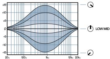
LOW MID is centered at 800Hz .
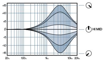
HI MID is centered at 3kHz
Midrange EQ is often considered the most dynamic, because the frequencies that define any sound are almost always found in this range.
33. LOW
This control is centered at 80Hz and below. This frequency represents the punch in kick drums, bass guitar and fat synth patches.
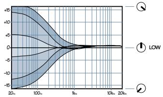
This graph shows various settings of the LOW control, with LOW CUT not engaged.
34. LOW CUT
This switch (only on the mono channels) cuts the bass frequencies below 75Hz at a rate of 18dB per octave. Low Cut is also known as High Pass (low cut dress=high pass rate).
To prevent muddy mixes, use low cut on every mono channel except those which carry kick drum, bass guitar or other bass-intensive sounds. Low cut can also help reduce the possibility of feedback in live situations and it helps to conserve amplifier power.

This graph shows various settings of the LOW control, with LOW CUT engaged.
Desirable low frequencies can be boosted whilst undesirable lower frequency stage rumble, mic handling clunks and P-p-pops are attenuated.
35. THIS OL' LED
This LED represents a bad thing: If a channel's OL LED lights up, its signal is too hot, and subsequent circuitry may overload (clip). To correct this, perform the SET THE LEVELS procedure on page 8.
36. -20 LED
This LED represents a good thing: This LED will flicker in time with a channel's signal when its level peaks at -20dB or higher. Also known as a "signal present indicator," it confirms an adequate signal level.
37. PAN
PAN adjusts the amount of channel signal sent, left versus right, to the MAIN OUTS (12) (16) and SUB OUTS (8). On mono channels, the knob places the signal somewhere between hard left and hard right. On stereo channels, it works as a balance control, by attenuating one side or the other.
With the PAN knob hard left, the signal will feed LEFT MAIN, SUB 1 or SUB 3, depending on the channel's L-R (41) and 1-2 & 3-4 (40) assignment settings.
With the PAN knob hard right, the signal will feed RIGHT MAIN, SUB 2 or SUB 4, also depending on the channel assignment settings.
With the PAN knob set somewhere in between, the signal will be shared across both sides of the mix(es).
The PAN circuits employ a design called "constant loudness." As the knob is rotated from left to center to right, the sound will remain at the same apparent volume. To attain this, both sides of the signal must dip down about 4 dB when panned center, to account for the "doubling" of the signal.
38. MUTE
Engaging a channel's mute switch severs its signal from all subsequent outputs. Additionally, the adjacent MUTE/SOLO LED will glow.
Note: A muted channel can still be soloed (set MODE (63) to PFL).
Note: The mixer's pre-fader aux sends, typically used for stage monitors, follow this mute switch. To effectively mute the signal sent to the main mix without muting monitor feeds, use that channel's fader instead of the mute switch.
39. SOLO
Engaging this switch isolates the associated channel's signal and sends it to the control room, phones and meters. See RUDE SOLO LIGHT (61) and MODE (63) for more information.
Note: A muted channel can still be soloed (set MODE (63) to PFL).
40. 1-2 & 3-4
Used in conjunction with the PAN (37) knob, these switches allow a channel signal to be sent to the subgroups in stereo pairs. Typically, if a channel signal is routed to the subgroups, it will not be directly assigned to the main mix via the L-R (41) switch.
For live sound, subgroups allow a group of channels to be controlled by one or two subgroup faders. For multi-track recording, subgroups can be used to route groups of channels to specific tracks of a multi-track recorder.
See PAN (37), L/R ASSIGN (59) and SUBGROUP FADER (60) for more information.
41. L-R
Used in conjunction with the PAN (37) knob, this switch allows a channel signal to be sent directly to the stereom main mix. Typically, an active channel will always have this switch engaged, unless its signal is being sent to a subgroup, via the 1-2 and 3-4 (40) switches.
See PAN (37) and MAIN MIX FADER (72) for more information.
42. CHANNEL FADER
The fader is the master level control for the channel's signal output. If the TRIM (25) is set correctly, the fader position will be best positioned somewhere between -20dB and 0dB (U).
If a fader is set all the way up, thereby adding 10dB of gain, that's a sign that the TRIM (25) is set too low. Conversely, if the fader is set way down, the TRIM may be set too high.
MASTER SECTION FEATURES
In the master section, signals leaving the channel strips are mixed, manipulated and sent to the outputs in the patchbay. Additionally, there are four more stereo inputs here, used to add effects to the main mix or other destinations.
45. LAMP
This female BNC connector provides 12 volts on its center pin. Connect any quality gooseneck lamp here.
AUX SEND MASTER: (46 and 47)
46. AUX SEND MASTERS
Aux send signals originate at each channel's AUX (26) knobs, are mixed together, sent through these controls, and exit at the patchbay's AUX SENDS (10). Turned fully up, these controls provide 15 dB of additional gain, the center "U" label is unity gain and fully down is off.
When an aux send is used for monitors, these knobs can be used to raise or lower individual monitor mixes to suit the performer's taste. For recording work, these knobs are typically set near unity and left alone; most adjustments are made per channel.
47. SOLO
Engaging any of these switches will isolate the associated signal and send it to the control room, phones and meters. See RUDE SOLO LIGHT (61) and MODE (63) for more information.
STEREO AUX RETURNS: (48 to 52)
48. STEREO AUX RETURNS
Having entered through the STEREO AUX RETURNS (9) jacks, effects returns are controlled by these knobs, and typically continue on to the MAIN MIX FADER (72). Effect returns are the "wet" signals, to be combined with the channels' original "dry" signals in the main mix.
Turned fully up, these controls provide 20 dB of additional gain; the center "U" label is unity gain and fully down is off. These knobs are typically set near unity and left alone.
49. TO AUX SEND 1-2
These knobs work just like the channel strip's AUX (26) 1 and 2 knobs; but here, the source signal is the STEREO AUX RETURNS (9) 1 and 2. Typically, these knobs are used to add effects to the stage monitors.
Via these knobs, aux return 1 combines its left and right sides to feed aux send 1; stereo aux return 2 combines to feed aux send 2. Turned fully up, these controls provide 15 dB of additional gain, the center "U" label is unity gain and fully down is off.
50. ASSIGN TO SUB and 51. SUB
These switches allow stereo aux return 4 to be sent to pairs of subgroups, instead of being sent directly to the main mix. Engage ASSIGN TO SUB (50) to divert aux return 4 to the subgroups; use SUB (51) to choose the subgroup pair, 1-2 (switch up) or 3-4 (switch down).
For live sound, subgroups allow a group of channel levels (and aux return 4) to be controlled by one or two subgroup faders. For multi-track recording, subgroups can be used to route groups of channels (and aux return 4) to specific tracks of a multi-track recorder.
See L/R ASSIGN (59) and SUBGROUP FADER (60) for more information.
52. SOLO
Engaging this switch isolates the associated signal and sends it to the control room, phones and meters. See RUDE SOLO LIGHT (61) and MODE (63) for more information.
Note: In PFL mode, aux returns are not soloed before their master level controls, but are instead summed after the controls into a mono signal and sent to the PFL mix.
53. TAPE RETURN
Having entered through the TAPE IN (6) jacks, tape returns are controlled by this knob, and then sent to TAPE RETURN TO PHONES/ C-R (69) and TAPE RETURN TO MAIN MIX (71).
Turned fully up, this provides 20dB of additional gain, the center "U" label is unity gain and fully down is off. This knob is typically set near unity and left alone.
54. METERS
The mixer's peak metering system is made up of two columns of thirteen LEDs each, with thresholds ranging from -40dB up to "CLIP" (+22dB at TRS MAIN OUTS (12), +28dB at the XLR MAIN OUT (16)).
The meters display the main mix, post MAIN MIX FADER (72). However, when a SOLO (39) (47) (52) (57) switch is engaged, the meters will instead display the solo information.
A good mix will show the meter's peaks flashing anywhere between -10 and +10dB . Remember that most amplifiers clip at about +10dB , and some recorders aren't so forgiving either. For best real-world results, try to keep your peaks between "0" and "+"
ZERO EQUALS ZERO

You may already be familiar with +4 and -10 operating levels. Basically, what determines an operating level, besides available headroom, is the relative
0dB VU chosen for the meters. A +4 mixer, with a +4dBu output signal, will actually display 0dB on its meters. A -10 mixer, with a -10dBV output signal, will also display 0dB.
To eliminate that confusion, Mackie's compact mixers use a simpler method, where zero equals zero: 0dBu (0.775V) at the output shows as 0dB VU on the meters. If a "+" output is desired, set the mix levels so the meters "average" at +4dB. If a "-10" output is desired, set the mix levels so the meters "average" at -10dB.
55. POWER LED
This LED glows when the POWER (20) switch is turned on.
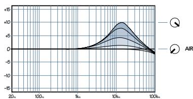
SUBGROUPS: (56 through 60)
56. AIR
AIR is a high frequency peaking EQ centered at 16kHz . Turned fully up, these controls provide 10dB of boost and fully down effectively bypasses the circuit. Use AIR to provide a crystalline effect to subgroups, helping them stand out in the overall mix.
57. SOLO
Engaging this switch isolates the associated signal and sends it to the control room, phones and meters. See RUDE SOLO LIGHT (61) and MODE (63) for more information.
Note: To solo a subgroup in AFL mode, L/R ASSIGN (59) must be engaged.
58. PAN
When a mono subgroup signal is assigned to the main mix via L/R ASSIGN (59), it effectively becomes another channel signal and can be panned from left to right. This knob then adjusts the amount of signal sent, left versus right, to the MAIN OUTS (12) (16).
The mixer's pan circuits employ a design called "constant loudness." As the knob is rotated from left to center to right, the sound will remain at the same apparent volume. To attain this, both sides of the signal must dip down about 4 dB when panned center, to account for the "doubling" of the signal.
59. L/R ASSIGN
This switch allows a subgroup signal to be sent to the main mix. Engaging this switch will not interrupt signal at the SUB OUTS (8) jack.
For live sound, subgroups allow a group of channels to be controlled by one or two subgroup faders, and then sent to the main mix using this switch and its associated PAN (58) control.
For multi-track recording, subgroups can be used to route groups of channels to specific tracks of a multi-track recorder via the SUB OUTS (8). In this case, L/R ASSIGN should not be used.
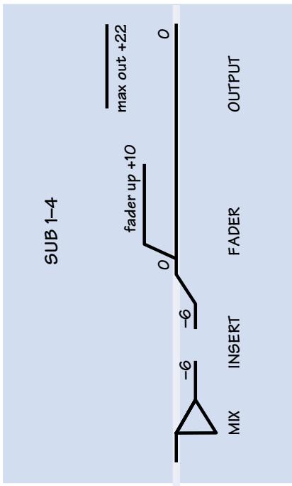
60. SUBGROUP FADERS
These faders provide 10dB of gain fully up, unity gain at the "U" label and are effectively muted fully down. Each fader is the master level control for a subgroup's signal, affecting both the SUB OUTS (8) and the main mix, via L/R ASSIGN (59).
SOLO: (61 through 65)
61. RUDE SOLO LIGHT
Engaging any SOLO switch (39),(47),(52) or (57) has this result: The CONTROL ROOM OUT (11), PHONES (18) and METERS (54), which ordinarily receive the main mix signals, will instead receive the solo signal. The MAIN OUTS (12) (16) and MONO MAIN OUT (14) are not affected by a solo condition.
Additionally, an LED associated with the solo switch and the RUDE SOLO LIGHT will blink obnoxiously.
The solo signal will be mono in PFL or stereo in AFL, as determined via the MODE (63) switch. Any number of solo switches may be simultaneously engaged.
62. LEVEL
This is the master level control for all solo signals, regardless of MODE (63). It can be set as desired, as it only affects the CONTROL ROOM OUT (11) and PHONES (18). It does not affect the solo levels sent to the METERS (54).
63. MODE
With this switch up, solo signals are PFL (pre-fader listen). With this switch down, solo signals are AFL (after-fader listen).
In PFL mode, the solo signal is tapped (mono) before a circuit's associated level control (except aux return SOLO (52)). PFL is popular for live sound applications; providing quick inspections of individual or multiple channels, even if their level controls are turned fully down.
Note: In PFL mode, when engaging a solo switch whose associated level control is set well below "U" (unity gain), turn down solo LEVEL (62) to compensate for the difference.
In AFL mode, the solo signal is tapped (stereo) after a circuit's associated controls (trim, EQ, pan, fader, mute, etc.). It's the equivalent of muted all the other channels. AFL is popu
lar for studio recording applications; providing the actual outputs of individual or multiple channels.
64. AUX LED
Along with the RUDE SOLO LIGHT (61), this LED blinks when any aux send master SOLO (47) or the global aux return SOLO (52) is engaged.
65. SUB LED
Along with the RUDE SOLO LIGHT (61), this LED blinks when any subgroup SOLO (57) is engaged.
TALKBACK: (66 through 68)
66. LEVEL
Having entered through the TALKBACK MIC (17) jacks, talkback level is controlled by this knob, and then sent to the MAIN MIX (67) and AUX 1-2 (68) switches. It can be set as desired by the engineer.
67. MAIN MIX
Engaging this switch sends the talkback signal to the main mix, allowing the user to speak to the audience (live sound), or to slate a song's start (studio recording).
To prevent the possibility of feedback, engaging this switch will attenuate control room output levels by 20dB.
68. AUX 1-2
Engaging this switch sends the talkback signal to aux sends 1 and 2, allowing the user to speak to the talent, providing that they are using those aux sends for monitoring.
To prevent the possibility of feedback, engaging this switch will attenuate control room output levels by 20dB.
69. TAPE RETURN TO PHONES/C-R
Ordinarily, the main mix (or solo) stereo signal is sent to the control room and phones. Engaging this switch will replace that with stereo signal from the TAPE IN (6) jacks, via the TAPE RETURN (53) level control.
It's typically used for studio recording, to patch a mixdown deck's outputs directly to the control room and phones; thereby always listening to the mixdown deck, whether it's in playback or input mode.
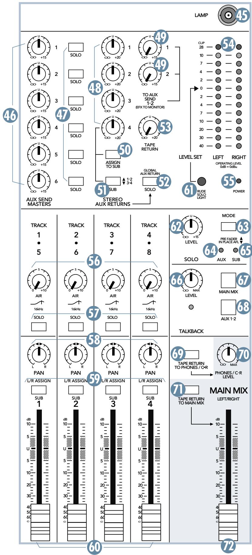
70. PHONES/C-R LEVEL
After the MAIN MIX FADER (72), the main mix is sent to the MAIN OUTS (12) (16) and MONO MAIN OUT (14). It is also sent through this control, and exits at CONTROL ROOM OUT (11) and PHONES (18).
This knob allows engineer's listening levels to be set as desired without disturbing the main mix outputs. Engaging TAPE RETURN TO PHONES/C-R (69) or TAPE RETURN TO MAIN MIX (71) will replace the main mix signal at the control room and phones outputs with the TAPE IN (6) signal.
When a channel's SOLO (39) is engaged, the main mix signal will be replaced by the solo signal(s), allowing the engineer to audition channels without disturbing the main mix.
To prevent the possibility of feedback, engaging either talkback switch (67) (68) will attenuate control room output levels by 20dB .
71. TAPE RETURN TO MAIN MIX
Ordinarily, the main mix (or solo) stereo signals are sent to CONTROL ROOM OUT (11), MAIN OUTS (12) (16), MONO MAIN OUT (14), PHONES (18) and METERS (54). Engaging this switch will replace these signals with stereo signals from the TAPE IN (6) jacks, via the TAPE RETURN (53) level control.
Also known as a "break switch," this switch is useful for live sound, to play recorded entertainment between sets. It can also serve as a global mute switch simply by patching nothing into the TAPE IN (6) jacks.
72. MAIN MIX FADER
This fader controls the main mix levels sent to CONTROL ROOM OUT (11), MAIN OUTS (12) (16), MONO MAIN OUT (14), PHONES (18) and METERS (54). The stereo main mix can be processed before this fader by patching an effects device into the MAIN INSERTS (13).
The fader turned fully up provides 10 dB of additional gain, the "U" label is unity gain and fully down is effectively muted. Typically, this fader is set near the "U" label and left alone, but it can be used for song fade-outs or quick system-wide mutes.
24-4-VLZ PRO and 32-4-VLZ PRO
Noise (20Hz to 20kHz bandwidth, Line inputs to Main L/R outputs, all channels assigned, panned L/R):
| Master fader down, Ch. gains down | -94.7dBu |
| Master fader @ unity, Ch. gains down | -87.4dBu |
| Master fader @ unity, Ch. gains @ unity | -83.5dBu |
Total Harmonic Distortion
(1kHz@+14dBu20Hz - 20kHz)
| Mic input to insert output | <0.0007% |
| Other outputs | < 0.004% |
Crosstalk (1kHz @ 0dBu, 20Hz to 20Khz bandwidth, channel in to Main Left outputs):
| Channel fader down, channels at Unity | -89.5dB |
| Channel muted, channels 2–16 at Unity | -88.7dB |
Frequency Response (any input to any output):
| 20Hz to 50KHz | +0/-1dB |
| 20Hz to 100KHz | +0/-3dB |
Maximum Levels
| Mic preamp input | +22dBu |
| All other inputs | +22dBu |
| Balanced XLR outputs | +28dBu |
| All other outputs | +22dBu |
Impedances
| Mic preamp input | 1.5kΩ |
| All other inputs | >10kΩ |
| All outputs | 120Ω |
Equalization
| Lo EQ Shelving 80Hz | ±15dB |
| Mid EQ(mono ch)Peak 100-8kHz | ±15dB |
| Hi EQ Shelving 12kHz | ±15dB |
Microphone Preamp
E.I.N. (150Ω terminated, max gain): -129.5dBm
Power Requirements
110 watts
Weight
| 24•4-VLZ PRO | 31 lbs. (14 kg.) |
| 32•4-VLZ PRO | 40.7 lbs. (18.8 kg.) |
Since we are always striving to make our products better by incorporating new and improved materials, components, and manufacturing methods, we reserve the right to change these and other specifications at any time without notice.
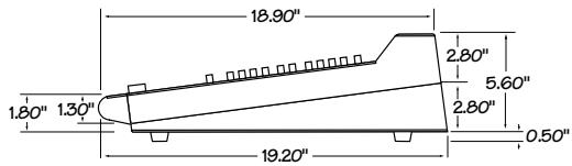

19.20"

BLOCK DIAGRAM

SERVICE INFORMATION
TROUBLESHOOTING
If you think your Mackie product has a problem, please do everything you can to confirm it before calling for service. Doing so might save you from the deprivation of your mixer and the associated suffering. Here's a few troubleshooting suggestions:
No channel signal
- Is the 1-2 & 3-4 (40) or L-R (41) switch set correctly?
- Is the CHANNEL FADER (42) turned up?
- Try soloing that channel. Does it appear on the METERS (54)?
- On mono channels, try unplugging any INSERT (3) effects devices.
- Try the same signal in another channel, set up exactly like the suspect channel.
No Output
- Are the L/R ASSIGN (59) switches set correctly?
Are the MAIN MIX FADER (72) or SUBGROUP FADERs (60) turned up? - Try unplugging any insert (7) (13) effects devices.
- If it's one of the MAIN OUTS (12) (16), try unplugging the other. For example, if it's the MAIN OUTS (TRS) (12), unplug the associated MAIN OUT (XLR) (16) output. If the problem goes away, it's not the mixer.
- If it's one bad side of a stereo pair, try switching them around. For example, if a left output is presumed dead, switch the left and right cords, at the mixer end. If the problem stays on the left side, it's not the mixer.
Noise
- Turn the CHANNEL FADERs (42) and STEREO AUX RETURNS (48) down, one by one. If the sound disappears, it's either that channel or whatever is plugged into it, so unplug whatever that is. If the noise disappears, it's from your whatever.
Power
Our favorite question: Is the POWER (20) switch on?
- Turn off the power from the wall, unplug the power cord and check the fuse (22).
REPAIR
Service for the 24-4-VLZ PRO and the 32-4-VLZ PRO is available at our factory, located in sunny Woodinville, Washington. Service for Mackie mixers living outside the United States can be obtained through local dealers or distributors.
If your mixer needs service, follow these instructions:
- Review the preceding troubleshooting suggestions. Please.
- Call Tech Support at 1-800-898-3211, 7 am to 5 pm PST, to explain the problem and request an RA (Return Authorization) number. Have your mixer's serial number ready.
You must have an RA number before you can obtain service at the factory.
- Keep this owner's manual. We don't need it to repair the mixer.
- Very Important: Move all Faders to their UP position as this will help prevent damage to the faders during shipping.
- Pack the mixer in its original package, including endcaps and box. This is very important. When you call for the RA number, please let Tech Support know if you need new packaging. Mackie is not responsible for any damage that occurs due to non-factory packaging.
- Include a legible note stating your name, shipping address (no P.O. boxes), daytime phone number, RA number, and a detailed description of the problem, including how we can duplicate it.
- Write the RA number in BIG PRINT on top of the box.
- Ship the mixer to us. We suggest insurance for all forms of cartage. Ship to this address:
MACKIE
SERVICE DEPARTMENT
16220 Wood-Red Rd. NE
Woodinville, WA 98072
- Ask Tech Support for the latest turnaround times when you call for your RA number. We normally send everything back prepaid using three-day shipping. However, if you rush your mixer to us by next day air, we'll treat it in kind by shipping it back the same way in which it was received. This paragraph does not necessarily apply to non-warranty service.
SR24-4/SR32-4 LIMITED WARRANTY
Please keep your sales receipt in a safe place.
A. LOUD Technologies warrants all materials, workmanship and proper operation of this product for a period of three years from the original date of purchase. If any defects are found in the materials or workmanship or if the product fails to function properly during the applicable warranty period, LOUD Technologies, at its option, will repair or replace the product. Labor for replacing all potentiometers is covered for the first year, after which it is excluded from warranty coverage and may be billed to you. This warranty applies only to equipment sold and delivered within the U.S. by LOUD Technologies or its authorized dealers.
B. Failure to register online or return the product registration card will not void the three-year warranty.
C. Service and repairs of Mackie products are to be performed only at the factory (see D below) OR at an Authorized Mackie Service Center (see E below). Unauthorized service, repairs, or modification will void this warranty.
D. To obtain factory service:
- Call LOUD Technologies at 800/898-3211, 7 am to 5 pm Monday through Friday (Pacific Time) to get a Return Authorization (RA). Products returned without an RA number will be refused.
- Pack the product in its original shipping carton. If you do not have the carton, just ask for one when you get your RA number, and we'll send a shipping carton out promptly. More information on packing can be found in the Service section of this manual. Do not use "packing peanuts," shredded newspapers, or other material with small particles, old underwear, or socks. Please seal the Mackie product in a plastic bag.
- Also include a note explaining exactly how to duplicate the problem, a copy of the sales receipt with price and date showing, and your return street address (no P.O. boxes or route numbers, please!). If we cannot duplicate the problem or establish the starting date of your Limited Warranty, we may, at our option, charge for service time.
- Ship the product in its original shipping carton, freight prepaid to:
MACKIE
SERVICE DEPARTMENT
16220 Wood-Red Rd. NE
Woodinville, WA 98072 USA
IMPORTANT: Make sure that the RA number is plainly written on the shipping carton.
E. To obtain service from an Authorized Mackie Service Center:
- Call LOUD Technologies at 800/898-3211, 7 am to 5 pm Monday through Friday (Pacific Time) to get:
1) The name and address of your nearest Authorized Mackie Service Center and 2) A return authorization (RA). You must have an RA number before taking your unit to a service center. - Make sure that you have a copy of your product's sales receipt from the store where you bought the product. It is necessary to establish purchase date and thus determine whether or not your product is still under warranty. If you can't find it, the Authorized Service Center may charge you for repairs even if your product is still covered by Mackie's Three-Year Limited Warranty.
-
Make sure that the problem can be duplicated. If you bring your product to an Authorized Service Center and they can't find anything wrong with it, you may be charged a service fee.
-
If the Authorized Mackie Service Center is located in another city, pack the product in its original shipping carton. More information on packing can be found in the Service section of this manual.
- Contact the Authorized Mackie Service Center to arrange service or bring the product to them.
F. LOUD Technologies and Authorized Mackie Service Centers reserve the right to inspect any products that may be the subject of any warranty claims before repair or replacement is carried out. LOUD Technologies and Authorized Mackie Service Centers may, at their option, require proof of the original date of purchase in the form of a dated copy of the original dealer's invoice or sales receipt. Final determination of warranty coverage lies solely with LOUD Technologies or its Authorized Service Centers.
G. Any Mackie product deemed eligible for repair or replacement under the terms of this warranty will be repaired or replaced within thirty days of receipt by LOUD Technologies. LOUD Technologies may use refurbished parts for repair or replacement of any product. Products returned to LOUD Technologies that do not meet the terms of this Warranty will be repaired and returned C.O.D. with billing for labor, materials, return freight, and insurance. Products repaired under warranty at the factory will be returned freight prepaid by LOUD Technologies to any location within the boundaries of the USA.
H. LOUD Technologies warrants all repairs performed for 90 days or for the remainder of the original warranty period. LOUD Technologies assumes no responsibility for the quality or timeliness of repairs performed by Authorized Mackie Service Centers.
I. This warranty is extended to the original purchaser and to anyone who may subsequently purchase this product within the applicable warranty period. A copy of the original sales receipt is required to obtain warranty repairs.
J. This is your sole warranty. LOUD Technologies does not authorize any third party, including any dealer or sales representative, to assume any liability on behalf of LOUD Technologies or to make any warranty for LOUD Technologies Inc..
K. THE WARRANTY GIVEN ON THIS PAGE IS THE SOLE WARRANTY GIVEN BY LOUD TECHNOLOGIES INC. AND IS IN LIEU OF ALL OTHER WARRANTYES, EXPRESS AND IMPLIED, INCLUDING THE WARRANTYES OF MERCHANTABILITY AND FITNESS FOR A
PARTICULAR PURPOSE. THE WARRANTY GIVEN ON THIS PAGE SHALL BE STRICTLY LIMITED IN DURATION TO THREE YEARS FROM THE DATE OF ORIGINAL PURCHASE FROM AN AUTHORIZED MACKIE DEALER. UPON EXPIRATION OF THE APPLICABLE
WARRANTY PERIOD, MACKIE SHALL HAVE NO FURTHER WARRANTY OBLIGATION OF ANY KIND. LOUD TECHNOLOGIES INC. SHALL NOT BE LIABLE FOR ANY INCIDENTAL, SPECIAL, OR CONSEQUENTIAL DAMAGES THAT MAY RESULT FROM ANY DEFECT IN THE MACKIE PRODUCT OR ANY WARRANTY CLAIM. Some states do not allow exclusion or limitation of incidental, special, or consequential damages or a limitation on how long warranties last, so some of the above limitations and exclusions may not apply to you. This warranty provides specific legal rights and you may have other rights which vary from state to state.

MACKIE®
LOUD Technologies Inc.
16220 Wood-Red Road NE·Woodinville, WA 98072·USA
US and Canada: 800.258.6883
Europe, Asia, Central and South America: 425.487.4333
Middle East and Africa: 31.20.654.4000
Fax: 425.487.4337 • www.mackie.com
E-mail: sales@mackie.com