
MM-10 MIXER - Audio Mixer JBSYSTEMS LIGHT - Free user manual and instructions
Find the device manual for free MM-10 MIXER JBSYSTEMS LIGHT in PDF.

| Product type | Audio mixing console (P.A.) |
| Brand | JBSYSTEMS LIGHT |
| Model | MM-10 MIXER |
| Channels | 6 mono channels, 2 stereo channels |
| Inputs | Mic (XLR), line (6.35 mm jack) per channel; stereo RCA input for playback |
| Outputs | Master (XLR), Aux (6.35 mm jack), Record (RCA), Headphone (6.35 mm stereo jack) |
| Equalizer | 3-band per channel (Lo, Mid, Hi) with +/-16 dB adjustment |
| Auxiliary sends | 2 sends (1 post-fade, 1 pre-fade) |
| Phantom power | 48 V, switchable |
| Frequency response | 15 - 20,000 Hz |
| Total harmonic distortion + noise | < 0.01% @ 1 kHz, 0 dB |
| Signal to noise ratio | 80 dB (IHF-A) |
| Power supply | AC 230 V, 50 Hz ; fuse 1 A/250 V |
| Dimensions (W x H x D) | 483 x 360 x 80 mm |
| Weight | 7.8 kg |
| Cleaning | Soft slightly damp cloth ; do not use solvents |
| Safety | Do not open the device ; use indoors ; max temperature 40°C ; unplug before maintenance |
| Spare parts | Main fuse (1 A/250 V) replaceable by qualified personnel |
| Repairability | Any repairs should be carried out by a qualified technician |
| Rack installation | Possible, use front mounting holes (screws not provided) |
Frequently Asked Questions - MM-10 MIXER JBSYSTEMS LIGHT
User questions about MM-10 MIXER JBSYSTEMS LIGHT
0 question about this device. Answer the ones you know or ask your own.
Ask a new question about this device
Download the instructions for your Audio Mixer in PDF format for free! Find your manual MM-10 MIXER - JBSYSTEMS LIGHT and take your electronic device back in hand. On this page are published all the documents necessary for the use of your device. MM-10 MIXER by JBSYSTEMS LIGHT.
USER MANUAL MM-10 MIXER JBSYSTEMS LIGHT
Copyright © 2007 by BEGLEC cva.
Reproduction or publication of the content in any manner, without express permission of the publisher, is prohibited.

Version: 1.1
JBSYSTEMS
Operation Manual EN
Mode d'emploi FR
Dispose of the unit and used batteries in an environment friendly manner according to your country regulations.
FR-DECLASSES L'APPAREIL
Thank you for buying this JB Systems® product. To take full advantage of all possibilities, please read these operating instructions very carefully.
FEATURES
This unit is radio-interference suppressed. This appliance meets the requirements of the current European and national guidelines. Conformity has been established and the relevant statements and documents have been deposited by the manufacturer.
10-channel P.A. mixer
- Suited for microphone mixing or small bands
- 6 mono channels, 2 stereo channels
- Balanced mic input and line input on each channel
3-band tone control on each channel
2 auxiliary outputs
- Extra line input that can be directly injected to the master
48V Phantom power supply
Balanced left and right master output
BEFORE USE
- Before you start using this unit, please check if there's no transportation damage. Should there be any, do not use the device and consult your dealer first.
- Important: This device left our factory in perfect condition and well packaged. It is absolutely necessary for the user to strictly follow the safety instructions and warnings in this user manual. Any damage caused by mishandling is not subject to warranty. The dealer will not accept responsibility for any resulting defects or problems caused by disregarding this user manual.
- Keep this booklet in a safe place for future consultation. If you sell the fixture, be sure to add this user manual.
- To protect the environment, please try to recycle the packing material as much as possible.
Check the contents:
Check that the carton contains the following items:
- User manual
MM-10 unit - Mains cable
SAFETY INSTRUCTIONS:

CAUTION
RISK OF ELECTRIC SHOCK DO NOT OPEN

CAUTION: To reduce the risk of electric shock, do not remove the top cover. No user-serviceable parts inside. Refer servicing to qualified service personnel only.

The lightning flash with arrowhead symbol within the equilateral triangle is intended to alert the use or the presence of un-insulated "dangerous voltage" within the product's enclosure that may be of sufficient magnitude to constitute a risk of electric shock.


The exclamation point within the equilateral triangle is intended to alert the user to the presence of important operation and maintenance (servicing) instructions in the literature accompanying this appliance.
This symbol means: indoor use only.

This symbol means: Read instructions.
- To prevent fire or shock hazard, do not expose this appliance to rain or moisture.
- To avoid condensation to be formed inside, allow the unit to adapt to the surrounding temperatures when bringing it into a warm room after transport. Condense sometimes prevents the unit from working at full performance or may even cause damages.
- This unit is for indoor use only.
- Don't place metal objects or spill liquid inside the unit. No objects filled with liquids, such as vases, shall be placed on this appliance. Electric shock or malfunction may result. If a foreign object enters the unit, immediately disconnect the mains power.
- No naked flame sources, such as lighted candles, should be placed on the appliance.
- Don't cover any ventilation openings as this may result in overheating.
- Prevent use in dusty environments and clean the unit regularly.
- Keep the unit away from children.
- Inexperienced persons should not operate this device.
Maximum save ambient temperature is 40^ . Don't use this unit at higher ambient temperatures. - Always unplug the unit when it is not used for a longer time or before you start servicing.
- The electrical installation should be carried out by qualified personal only, according to the regulations for electrical and mechanical safety in your country.
- Check that the available voltage is not higher than the one stated on the rear panel of the unit.
- The socket inlet shall remain operable for disconnection from the mains.
- The power cord should always be in perfect condition: switch the unit immediately off when the power cord is squashed or damaged.
- Never let the power-cord come into contact with other cables!
- When the power switch is in OFF position, this unit is not completely disconnected from the mains!
- This appliance must be earthed to in order comply with safety regulations.
- In order to prevent electric shock, do not open the cover. Apart from the mains fuse there are no user serviceable parts inside.
- Never repair a fuse or bypass the fuse holder. Always replace a damaged fuse with a fuse of the same type and electrical specifications!
- In the event of serious operating problems, stop using the appliance and contact your dealer immediately.
- Please use the original packing when the device is to be transported.
- Due to safety reasons it is prohibited to make unauthorized modifications to the unit.
INSTALLATION GUIDELINES:
- Install the unit in a well-ventilated location where it will not be exposed to high temperatures or humidity.
- Placing and using the unit for long periods near heat-generating sources such as amplifiers, spotlights, etc. will affect its performance and may even damage the unit.
- The unit can be mounted in 19-inch racks. Attach the unit using the 4 screw holes on the front panel. Be sure to use screws of the appropriate size. (screws not provided) Take care to minimize shocks and vibrations during transport.
- When installed in a booth or flight case, please make sure to have good ventilation to improve heat evacuation of the unit.
- To avoid condensation to be formed inside, allow the unit to adapt to the surrounding temperatures when bringing it into a warm room after transport. Condense sometimes prevents the unit from working at full performance.
CLEANING THE APPLIANCE:
Clean by wiping with a polished cloth slightly dipped with water. Avoid getting water inside the unit. Do not use volatile liquids such as benzene or thinner which will damage the unit.
CONNECTIONS
For more information on connections, please refer to the next chapter.
Be sure to turn off the mixer before you make changes to the different connections.
In this manual we talk about "line inputs". This is a global name for inputs with a level between 750mV and 2V. This includes tuners, videos, CD-players, etc.
FUNCTIONS
MONO MICROPHONE/LINEINPUT CHANNEL
1. 3 PIN FEMALE XLR SOCKET INPUT
Balanced input wiring: Pin 1 = Ground (sleeve)
Pin 2 = Positive signal
Pin 3 = Negative signal
Unbalanced input wiring:
Pin 1 = Ground
Pin 2 = Signal
Pin 3 = Ground
Input impedance: 2k Ohm
Input sensitivity: 0.8mV RMS (-60dB)
2. 1/4"STEREO JACK SOCKET INPUT
Balanced input wiring:
Tip = Positive signal
Ring = Negative signal
Sleeve = Ground
Unbalanced input wiring:
Tip = Signal
Ring = Ground
Sleeve = Ground
(Mono jack plug will automatically give this)
Input impedance: >50K Ohm
Input sensitivity: 25mV RMS (-30dB)
3. GAIN CONTROL
Allows maximum input signal control and will accommodate most microphones of both low or high impedance to 600 Ohm as well as Phantom Power (48 Volt) types. The line input can be anything from keyboard through to line level feeds from other equipment. Gain range:
XLR input +15 to +60dB
Jack input -15 to +30dB
4. CLIP LED
This warning will illuminate 4dB before clipping and will remain on for a short period. For optimal input channel running level, adjust Gain Control until Clip indicator illuminates while signal peaks are present. Then adjust the gain setting until Clip indicator is off. This will give optimal signal to noise.
5. EQ CONTROL 'HIGH'
This control allows 16dB of cut or boost to the high frequencies.
6. EQ CONTROL 'MID'
This control allows 16dB of cut or boost to the mid frequencies.
7. EQ CONTROL 'LOW'
This control allows 16dB of cut or boost to the low frequencies.
8. AUXSEND1
This auxiliary send control is 'Post-fade' and can be used to control the mix of inputs being processed by effects, etc. Its level will change with the channel fader (12).
9. AUXSEND2
This auxiliary send control is 'Pre-fade' and can be used to control the mix of inputs to an independent output such as monitoring. Its level will not change with channel fader (12).
Note: the Post-Fade option can only be selected by your service engineer.
10. PAN CONTROL
This control is used to set the stereo balance of the input signal and can 'Pan' it fully to the left or right.
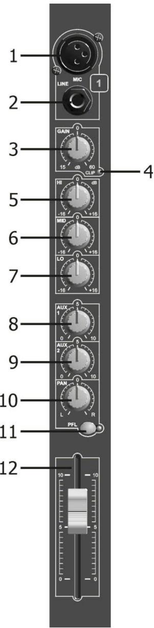
11. PFL SWITCH
This switch and indicator allows pre-fade listen of input signals through the headphone and Led meters (useful while setting gains or trouble shooting).
12. 60mmFADER
This slide control provides level control of input signal to the main stereo mix output and will also control the Post-Fade Aux Send 1.
STEREO LINE INPUT CHANNEL
1. LINE INPUT LEFT OR MONO - 1/4" Mono Jack Socket
If the input is connected to a mono source use this connection only as the signal will automatically be routed to the right input also.
Input wiring:
Tip = Signal Sleeve = Ground
Input impedance: 10K Ohm
Input sensitivity: 24.5mV (-30dBm)
2. LINE INPUT RIGHT - 1/4" Mono Jacket Socket
Input wiring:
Tip = Signal Sleeve = Ground
Input impedance: 10K Ohm
Input sensitivity: 24.5mV (-30dBm)
3. PAD SWITCH
Operation of this switch reduces the input sensitivity by 10Db allowing it to be used with high output devices such as CD players as well as musical instruments.
4. GAIN CONTROL
The panel marking at 0dB is a true reference to 0dBm when the -10dB Pad is engaged.
Range: +10dB
5. CLIP LED
This warning light will illuminate 4dB before clipping and will remain on for a short period. For optimal input channel running level, adjust Gain Control until Clip indicator illuminates while signal peaks are present. Then adjust the gain setting until Clip indicator is off. This will give optimal signal to noise.
Note: If EQ controls are altered this Gain/Clip setting will need adjustment.
6. EQ CONTROL 'HIGH'
This control allows 16dB of cut or boost to the high frequency content of the input signal.
7. EQ CONTROL 'MID'
This control allows 6dB of cut or boost to the mid frequencies.
8. EQ CONTROL 'LOW'
This control allows 6dB of cut or boost to the low frequencies.
9. AUXSEND1
This auxiliary send control is 'Post-fade' and can be used to control the mix of inputs being processed by effects, etc. Its level will change with the input fader (13).
10. AUX SEND 2
This auxiliary send control is 'Pre-fade' and can be used to control the mix of inputs to an independent output such as monitoring. Its level will NOT change with input fader.
Note: The Post-fade option can only be selected by your service engineer.
11. BALANCE CONTROL
This control is used to set the stereo balance of the input signal and can pan it fully to the left or right.
12. PFL SWITCH
This switch and indicator allows pre-fade listen of input signals through the headphone and Led meters (useful while setting gains or trouble shooting).
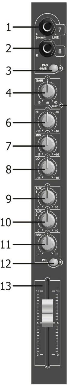
13. 60mm FADER
This Slide control provides level control of input signal to the main stereo mix output and will also control the Post-fade Aux Send 1.
STEREO OUTPUT CHANNEL
1. STEREO OUTPUT - 3 pin Male XLR Socket
Output wiring:
Balanced:
Unbalanced:
Pin 1=Ground
Pin 1 = Ground
(sleeve)
Pin 2 = Positive Signal
Pin 2 = Signal
Pin 3 = Negative Signal
Pin 3 = no
connection
Nominal Output Level:
Balanced +6dBm (1.55V RMS variable to +10/16dB)
Unbalanced 0dBm (0.775V RMS variable to +10/16dB)
Impedance:
Output: <50 Ohm Minimum Load: 600 Ohm
2. AUX SEND OUTPUT - 1/4" Jack Mono Socket (unbalanced) output
Output wiring:
Tip = Signal
Sleeve = Ground
Nominal Output Level:
0dBm (0.775V RMS variable to +10dBm)
Impedance:
Output: <50 Ohm Minimum Load: 5K Ohm
3. AUX RETURN LEFT/MONO - 1/4" Jack Mono Socket Input
(If used as mono input it will automatically connect the input to the AUX Return Right socket)
Output wiring:
Tip = Signal
Sleeve = Ground
Input impedance: 10K Ohm
Input sensitivity: 250mV RMS (-10DBm)
4. AUX RETURN RIGHT/MONO - 1/4" Jack Mono Socket Input
Same as (3) Aux Return Left/Mono.
5. LED METER
This is a 10 segment Led meter with VU calibration providing a signal monitor range from -20dB to 3dB with a change of colour at the nominal 0dB position.
6. AUX RETURN LEFT LEVEL CONTROL
This level control will set the desire amount of return signal on to the main left output mix only.
7. AUX RETURN RIGHT LEVEL CONTROL
This level control will set the desired amount of return signal on to the main right output mix only. (Use in conjunction with left level (6) when mixing a mono input signal)
8. MASTER AUX SEND OUTPUT LEVEL CONTROL
This level control sets the desired output level of Aux send mix to the output socket (it's best set at N^7 when Finally setting up). Subsequently adjust to level required by external equipment.
9. MASTER OUTPUT FADER CONTROL
This Slide control is used to set the required overall output level to the power amplifier (or other equipment). The calibration shows a suggested nominal running level, referenced '0' (10dB boost is available if required).
10. ON INDICATOR
This led indicates that the mixer power is on.
11. PHANTOM SWITCH
This switch is recessed to prevent accidental operation and has a corresponding red LED indicator; it should NOT be operated while the mixer is live.
NOTE:
It should be pre-selected during setting up with the main output faders and MIC input gain controls down.
- ALL XLR MIC inputs will be phantom powered when selected. Some microphones that do NOT require phantom supply may not operate or are damaged - check instructions.
- The Jack Line inputs will be unaffected and can be used as normal. (Your service station may be able to disable the Phantom Power)
12. STEREO RECORD OUTPUT - Left and Right RCA Socket Outputs (unbalanced)
The signal is derived from the main stereo output mix after the output faders. Nominal '0' Output Level: -10dBv(316mVRMS)
Output impedance: 600 Ohm
Load impedance (min): 5K Ohm
13. STEREO PLAYBACK INPUT - Left and Right RCA Socket Inputs (unbalanced)
Signal is routed to the main stereo output before the faders and the monitoring system. Normal Input Sensitivity: 316mV RMS (-10dBv)
Input impedance: 5K Ohm
14. PLAYBACK SWITCH
Allows ON/OFF control of Playback input signal onto the main stereo output mix.
15. PLAYBACK LEVEL CONTROL
Level control of the 2-track tape playback onto the main stereo output of the mixer (before the main output faders) set for desired mix.
16. TAPE MONITOR SWITCH
This switch sets the Headphone and Led Meter Monitoring system over to Tape Playback monitoring (Before the playback switch and level control).
17. PFL SWITCH
This switch sets the Headphone and Led Meters system over to PFL (input pre-fade listen) monitoring. It works in conjunction with PFL switches on each input channel.
18. HEADPHONE LEVEL CONTROL
This control is used in conjunction with the switch to monitor signals within the mixer. With both Tape Monitor and PFL switches 'OFF' the headphone system and Led meters will monitor the main stereo output.
19. HEADPHONE OUTPUT - 1/4" Stereo Jack Socket Output
Output wiring:
Tip = left signal
Ring = right signal
Sleeve = ground
Minimum Load impedance: 40 Ohm
SPECIFICATIONS
Power Supply: AC 230 V, 50Hz
Fuse: 1A/250V
Frequency response: 15-20.000Hz
THD + noise: <0.01% @ 1kHz, 0dB
Micro inputs: 200-600 Ohm/balanced
Line inputs: 300mV @ 10kΩ
Record output: 775mV @ 50kΩ
Master output: 775mV @ 600Ω
Tone controls: +/-16dB @ 10kHz/600Hz / 60Hz
Dimensions: 483(W) x 360(H) x 80(D) mm
Weight: 7.8kg
Every information is subject to change without prior notice
You can download the latest version of this user manual on our website: www.beglec.com
MODE D'EMPLOI
Mode non-balance: Pin 1 = Masse
Pin 2 = Point chaud
Pin 3 = Masse
Belasting (min): 5K Ohm
13. STEREO PLAYBACK INGANG - Linker en Rechter RCA Ingangen asymmetrisch)
- PRE-FADER LEVEL (PFL)
HIERMIT KONNEN SIE DAS SIGNAL EINES KANALS
KONTROLLIEREN. WENN DIE PFL TASTE GEDRÜCKT IST SIND
DIE ANDEREN KANÄLE AUTOMATISCH AUSGESCHALTED.
- 60mm FADER
- PRE-FADER LEVEL (PFL)
HIERMIT KÖNNEN SIE DAS SIGNAL EINES KANALS KONTROLLIEREN. WENN DIE PFL TASTE GEDRUCKT IST SIND DIE Anderen KANÄLE AUTOMATISCH AUSGESCHALTED.
- 60mm FADER
1 = Masa
2 = Senal
3 = Masa
Pin 1 = Terra (Manga)
Pin 2 = Sinal
Pin 3 = Sem ligação