
VX - Audio Amplifier JBSYSTEMS LIGHT - Free user manual and instructions
Find the device manual for free VX JBSYSTEMS LIGHT in PDF.

User questions about VX JBSYSTEMS LIGHT
0 question about this device. Answer the ones you know or ask your own.
Ask a new question about this device
Download the instructions for your Audio Amplifier in PDF format for free! Find your manual VX - JBSYSTEMS LIGHT and take your electronic device back in hand. On this page are published all the documents necessary for the use of your device. VX by JBSYSTEMS LIGHT.
USER MANUAL VX JBSYSTEMS LIGHT
Copyright © 2005 by BEGLEC cva.
Reproduction or publication of the content in any manner, without express permission of the publisher, is prohibited.

Version: 1.2
JBSYSTEMS
THE POWER SOURCE FOR DJ'S


DISPOSAL OF THE DEVICE
Dispose of the unit and used batteries in an environment friendly manner according to your country regulations.
DéCLASSES L'APPAREIL
Thank you for buying this JB Systems product. To take full advantage of all possibilities, please read these operating instructions very carefully.
FEATURES
- Professional amplifier for all-round sound reproduction
- Short Circuit protection
DC current protection
High temperature protection - Forced fan cooling
- Bridge function (except on AX400 / VX400)
- Built-in limiters (except on AX400 / VX400)
Balanced XLR and Jack inputs
Ground/lift switch - Speakon® compatible speaker outputs
- Binding post speaker outputs (screws)
- Strong Aluminum 19" front
BEFORE USE
Check that the carton contains the following items:
Power amplifier
- Operating instructions
- Mains power cable.
SAFETY INSTRUCTIONS:

CAUTION
RISK OF ELECTRIC SHOCK DO NOT OPEN

CAUTION: To reduce the risk of electric shock, do not remove any cover. No user-serviceable parts inside. Refer servicing to qualified service personnel only.

The lightning flash with arrowhead symbol within the equilateral triangle is intended to alert the use or the presence of un-insulated "dangerous voltage" within the product's enclosure that may be of sufficient magnitude to constitute a risk of electric shock.

The exclamation point within the equilateral triangle is intended to alert the user to the presence of important operation and maintenance (servicing) instructions in the literature accompanying this appliance.
To prevent fire or shock hazard, do not expose this appliance to rain or moisture. Do not place metal objects or spill liquid inside the turntable. Electric shock or malfunction may result.
SOME IMPORTANT INSTRUCTIONS:
- Always install this appliance in a well vented place. Avoid presence of heat sources.
- Avoid places that are dusty and humid.
- Don't cover any ventilation openings as this may result in overheating.
- Keep this booklet in a safe place for future consultation. If you sell the fixture, be sure to add this user manual.
- To prevent fire or shock hazard, do not expose this appliance to rain or moisture.
- In order to prevent electric shock, do not open the enclosure. If a problem occurs, contact your dealer.
- Do not place metal objects or spill liquid inside the unit. Electric shock or malfunction may result.
- To protect the environment, please try to recycle the packing material as much as possible.
CLEANING THE UNIT:
Clean by wiping with a cloth slightly dipped with water. Avoid getting water inside the unit.
Do not use volatile liquids such as benzene or thinner which will damage the unit.
Clean the ventilation holes regularly with a vacuum cleaner. This increases the cooling capacity of the amplifier fans and helps preventing temperature overheat.
CONNECTIONS
Be sure to turn off the unit before you make changes to the wiring. For the signal inputs we recommend using the XLR-connections. Use good quality signal cables to ensure excellent audio quality. For example use JB cables with order codes: 7-0061 (XLR/XLR L=1m) or 7-0063 (XLR/XLR L=5m). For the speakers we suggest using the Speakon® compatible outputs. Suitable cables are for example JB order codes: 2-0505 (L=5m) or 2-0510 (L=10m).
FRONT PANELS
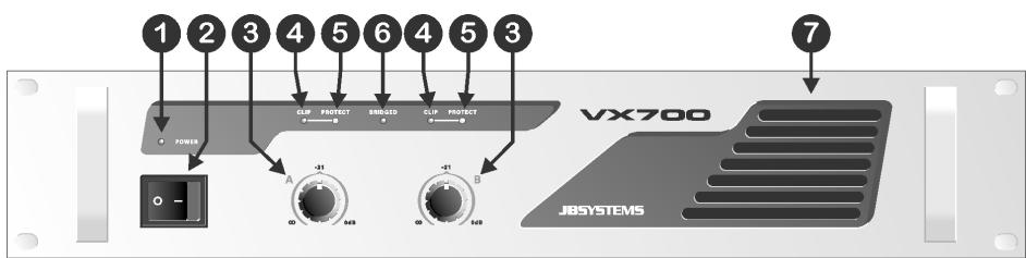
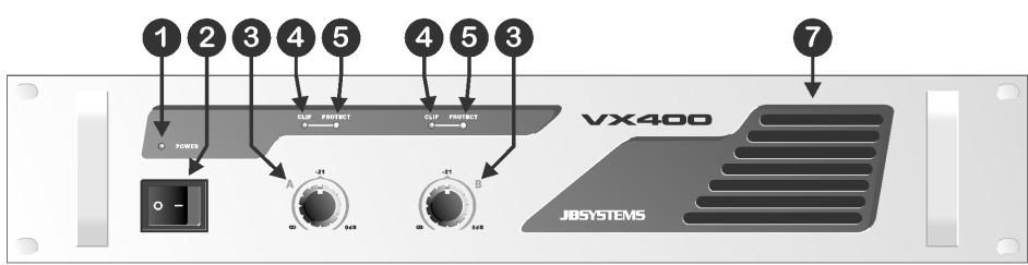
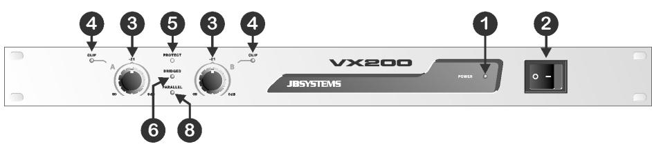
- POWER LED: This blue led is on when you turn the amplifier on using switch(2).
- MAINS SWITCH: Used to turn the amplifier on and off. A few seconds after switching on the amplifier it is ready for operation.
- GAIN CONTROLS: These potentiometers are used to control the input sensitivity of the amplifier. Each channel has its own control.
You can use these controls to set the maximum sound level of your setup:
- Turn both controls on the amplifier (3) to the left.
- Put on some music on and make sure the VU meters on your mixer are at 0dB. (from time to time the red zone is lit)
- Set the Master output from your mixer to maximum.
- Open the Gain controls from the amplifier (3) until the maximum desired sound level is reached.
- Make sure nobody can reach the Gain controls of the amplifier.
You have just set the maximum level the DJ is able to produce. Your neighbors will be glad... (in some cases the DJ is not )
Note for VX200 and AX700MK2 / VX700MK2: In Parallel and Bridge mode, only the gain control of the left channel is used to adjust the input sensitivity.
-
CLIP LED: Turns on just before the maximum, distortion free, output level of the amplifier. The clip leads may turn on shortly from time to time but they may certainly not turn on for longer periods. In this case you have to turn the output level down!
-
PROTECT LED: The protection LED is on when the speakers are disconnected from the amplifier. This occurs in the following situations:
-
During the first seconds after switching on the amplifier.
- When the temperature of the power stage becomes too high.
- In case of a technical defect: DC protection!
-
While switching the amplifier off, the "protect led" turns on for a short time.
-
BRIDGE LED: (only for VX200 and AX700MK2 / VX700MK2) Indicates that the amplifier is working in bridge mode. This means that both channels are switched together in series to act as one mono amplifier. The output power nearly doubles compared to the separate channels. However the impedance of the connected speaker cabinets must be twice compared to that of normal stereo mode. In bridge mode, you have to apply the signal only to the left input of the amplifier. The right input is not used. For more information refer to point (11) in the next chapter.
Attention: Take care not to use speaker cabinets with a total impedance lower than 8 . This will overload the amplifier!
- VENTILLATION HOLES: during its operation the amplifier produces heat that needs to be dissipated. The fans inside the amplifier must be able to evacuate the heat in the most effective way. Therefore is it very important not to cover any of the ventilation openings as this may result in overheating.
- PARALLEL MODE: (only for VX200) Indicates that the amplifier is working in parallel mode. This means that both channels are switched together in parallel to act as one mono amplifier. The output power nearly doubles compared to the separate channels. However the impedance of the connected speaker cabinets must be half compared to that of normal stereo mode. In parallel mode, you have to apply the signal only to the left input of the amplifier. The right input is not used. For more information refer to point (11) in the next chapter.
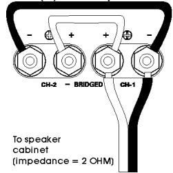
Attention: to be able to produce the indicated power, the total impedance of the connected speaker cabinets must be around 2
REAR PANELS
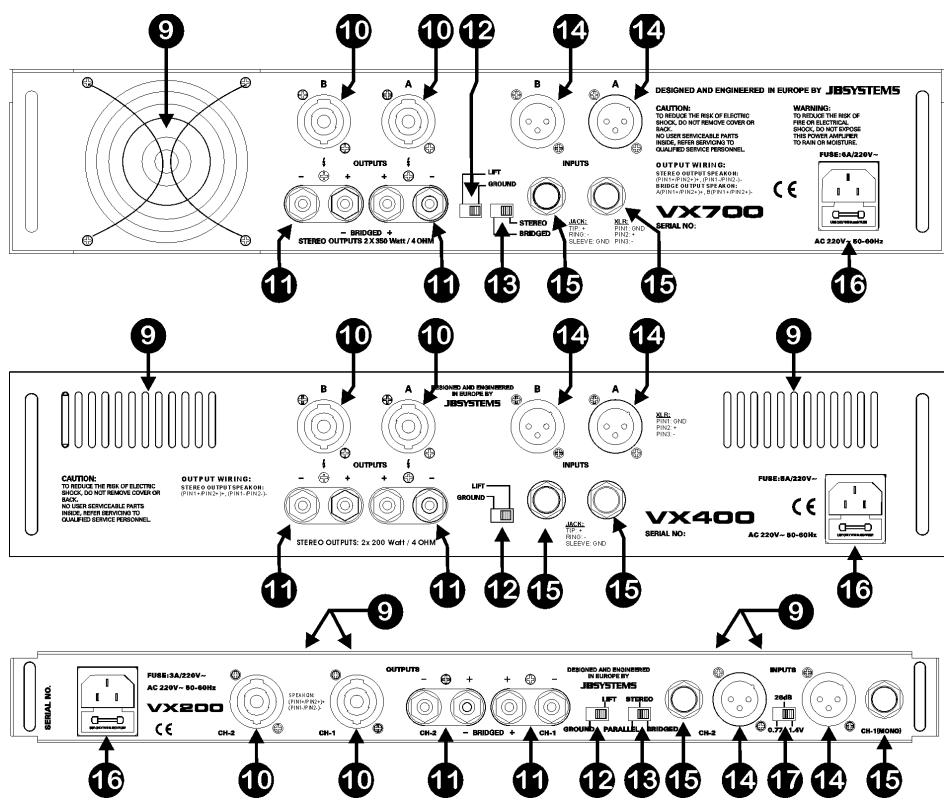
- FAN & VENTILLATION HOLES: during its operation the amplifier produces heat that must be dissipated. The fans inside the amplifier must be able to evacuate the heat in the most effective way. Therefore is it very important not to cover any of the ventilation openings as this may result in overheating.
10.SPEAKON OUTPUTS: use these Speakon® compatible connectors to connect your speaker cabinets. Refer to chapter "connections" to learn which cables are suitable. Wiring of these connectors is as follows:
- POS(+) = Speakon connector PIN1+ and PIN2+
- NEG(-) = Speakon connector PIN1- and PIN2-
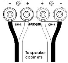
11.BINDING POST SPEAKER OUTPUTS: We strongly suggest you to use the Speakon® connectors as described above(10). If you don't have these or you want to use the amplifier in bridge or parallel mode, you can use the binding post connectors. Important: Use cables that have clear markings for + and - poles. We suggest using red/black cables (such as JB Systems order code: 935). It is very important that you don't switch the + and - poles of the outputs. This results in very poor sound reproduction without low frequencies! There are 3 ways to connect the speaker cabinets using the binding post connectors:
- STEREO MODE (most common): Connect the speaker cables as shown on the drawing below. Make sure not to switch the red and black wires. Be sure to set the switch on the rear panel to "stereo". On the AX400 / VX400 this switch is not available.

SWITCH ON THE REAR PANEL OF VX200

SWITCH ON THE REAR PANEL OF Vx700
- BRIDGE MODE: (only for VX200 and AX700MK2 / VX700MK2) Connect the speaker cables as shown on the drawing below. Be sure to set the switch on the rear panel to "bridge". Also refer to (6) in the previous chapter.
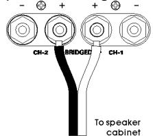
(impedance >8 OHM)
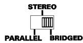
SWITCH ON THE REAR PANEL OF VX200

SWITCH ON THE REAR PANEL OF Vx700
- PARALLEL MODE: (only for VX200) Connect the speaker cables as shown on the drawing below. Be sure to set the switch on the rear panel to "parallel". Also refer to (8) in the previous chapter.

SWITCH ON THE REAR PANEL OF VX200
- GROUND LIFT switch: In some cases nasty hum noises can occur due to ground loops in your setup. Setting the Ground lift switch to the position "lift" breaks the ground loop between the amplifier and the chassis grounds of various other components in your setup. As a result the hum noises disappear.
13.MODE switch: (not for AX400 / VX400) Used to set the operation mode of the amplifier. The most common operation mode is "stereo". If you need more power, you can operate the amplifier in bridge or parallel mode. Refer to points (6), (8) and (11) for more information.
-
XLR inputs: You can connect these balanced inputs to balanced and unbalanced line level audio sources (example: DJ-mixer):
-
Balanced source: Use good quality XLR/XLR balanced audio cables. Example: JB Systems 7-0061 (XLR/XLR L=1m) or 7-0063 (XLR/XLR L Wiring of the XLR connector: PIN1: GND PIN2: pos+ PIN3: neg-.
- Unbalanced source: Use good quality XLR/cinch audio cables. Example: JB Systems 2-0445 (XLR/cinch L=1.5m)
15.JACK inputs: You can connect these balanced inputs to balanced and unbalanced line level audio sources (example: DJ-mixer):
- Balanced source: Use good quality JACK/JACK balanced audio cables. Wiring of the JACK connector: Sleeve: GND TIP: pos+ RING: neg-.
-
Unbalanced source: Use good quality JACK/cinch audio cables. Example: JB Systems 2-0430 (JACK/cinch L=1.5m) or 2-0435 (L=3.0m)
-
POWER input: Use the supplied power cable to connect the amplifier to the mains. This connector also holds a 20mm glass fuse. Always replace a blown fuse by another with exactly the same specifications. (fuse specifications can be found on the rear panel, next to the power input connector)
- INPUT SENSITIVITY switch: (only VX200) With this switch you can perfectly adapt the input sensitivity of the amplifier: 0,77V; 26dB or 1,4V.
SPECIFICATIONS
| MODEL | VX200 | AX400 / VX400 | AX700MK2 / VX700MK2 |
| Power stereo 4 ohm | 2x 110Wrms | 2x 200Wrms | 2x 350Wrms |
| Power stereo 8 ohm | 2x 65Wrms | 2x 135Wrms | 2x 200Wrms |
| Power bridge 8 ohm | 1x 220Wrms | *** | 1x 700Wrms |
| Power parallel 2 ohm | 1x 220Wrms | *** | *** |
| Freq. Resp. (+/-1.5dB) | 10 - 50000Hz | 10 - 50000Hz | 10 - 50000Hz |
| Input Sensitivity | 0,77V / 26dB / 1.4V | 0,77V | 0,77V |
| Input impedance | 20 kohm | 20 kohm | 20 kohm |
| S/R ratio | >85dB | >85dB | >85dB |
| Damping factor | >150 | >150 | >200 |
| Slew Rate | 40V/uS | 35V/uS | 60V/uS |
| Cooling | Force Fan cooling | Force Fan cooling | Force Fan cooling |
| Inputs | Balanced XLR/Jack | Balanced XLR/Jack | Balanced XLR/Jack |
| Outputs | Speakon/binding post | Speakon/binding post | Speakon/binding post |
| Power supply | AC230V / 50Hz | AC230V / 50Hz | AC230V / 50Hz |
| Dimensions (mm) | 44x483x320 (19"/1U) | 88x483x260 (19"/2U) | 88x483x260 (19"/2U) |