MM 14D - Audio Mixer JBSYSTEMS LIGHT - Free user manual and instructions
Find the device manual for free MM 14D JBSYSTEMS LIGHT in PDF.

User questions about MM 14D JBSYSTEMS LIGHT
0 question about this device. Answer the ones you know or ask your own.
Ask a new question about this device
Download the instructions for your Audio Mixer in PDF format for free! Find your manual MM 14D - JBSYSTEMS LIGHT and take your electronic device back in hand. On this page are published all the documents necessary for the use of your device. MM 14D by JBSYSTEMS LIGHT.
USER MANUAL MM 14D JBSYSTEMS LIGHT
Copyright © 2008 by BEGLEC cva.
Reproduction or publication of the content in any manner, without express permission of the publisher, is prohibited.

Version: 1.0
Operation Manual EN
Mode d'emploi FR
Dispose of the unit and used batteries in an environment friendly manner according to your country regulations.
FR-DECLASSES L'APPAREIL
Thank you for buying this JB Systems® product. To take full advantage of all possibilities, please read these operating instructions very carefully.
FEATURES
This unit is radio-interference suppressed. This appliance meets the requirements of the current European and national guidelines. Conformity has been established and the relevant statements and documents have been deposited by the manufacturer.
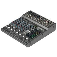
P.A. mixer with 14 inputs, perfect for microphone mixing or small bands
8 internal DSP-effects (reverb, echo, chorus, flanger, ...) with foot switch.
- Internal DSP-effects are switched off when the aux1-output is connected.
All input channels have:
○ Gain control
Hi, Mid, Low tone controls
o Aux1/internal effect (post fader)
○ Aux2 (switchable pre/post fader)
Pan/balance control
PFL switch
Channel ON/OFF switch
- 6 mono channels also have:
Balanced line input (Jack)
Balanced microphone (XLR)
48V Phantom power supply
Inserts (for external effect equipment)
o Selectable 75Hz low cut filter
Clip indicator
4 stereo channels also have:
o Balanced line input (2 jacks: left+right)
Mono/stereo switch (mono: L input to L+R)
Aux send/return masters
- Extra stereo RCA tape deck input/output with tape monitor
Balanced left and right master output
BEFORE USE
- Before you start using this unit, please check if there's no transportation damage. Should there be any, do not use the device and consult your dealer first.
- Important: This device left our factory in perfect condition and well packaged. It is absolutely necessary for the user to strictly follow the safety instructions and warnings in this user manual. Any damage caused by mishandling is not subject to warranty. The dealer will not accept responsibility for any resulting defects or problems caused by disregarding this user manual.
- Keep this booklet in a safe place for future consultation. If you sell the fixture, be sure to add this user manual.
- To protect the environment, please try to recycle the packing material as much as possible.
Check the contents:
Check that the carton contains the following items:
- User manual
MM-14D unit
Power Supply
SAFETY INSTRUCTIONS:

CAUTION
RISK OF ELECTRIC SHOCK DO NOT OPEN

CAUTION: To reduce the risk of electric shock, do not remove the top cover. No user-serviceable parts inside. Refer servicing to qualified service personnel only.

The lightning flash with arrowhead symbol within the equilateral triangle is intended to alert the use or the presence of un-insulated "dangerous voltage" within the product's enclosure that may be of sufficient magnitude to constitute a risk of electric shock.

The exclamation point within the equilateral triangle is intended to alert the user to the presence of important operation and maintenance (servicing) instructions in the literature accompanying this appliance.
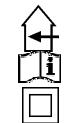
This symbol means: indoor use only
This symbol means: Read instructions
This symbol means: Safety Class II appliance
- To prevent fire or shock hazard, do not expose this appliance to rain or moisture.
- To avoid condensation to be formed inside, allow the unit to adapt to the surrounding temperatures when bringing it into a warm room after transport. Condense sometimes prevents the unit from working at full performance or may even cause damages.
- This unit is for indoor use only.
- Don't place metal objects or spill liquid inside the unit. No objects filled with liquids, such as vases, shall be placed on this appliance. Electric shock or malfunction may result. If a foreign object enters the unit, immediately disconnect the mains power.
- No naked flame sources, such as lighted candles, should be placed on the appliance.
- Don't cover any ventilation openings as this may result in overheating.
- Prevent use in dusty environments and clean the unit regularly.
- Keep the unit away from children.
- Inexperienced persons should not operate this device.
Maximum save ambient temperature is 40^ . Don't use this unit at higher ambient temperatures. - Always unplug the unit when it is not used for a longer time or before you start servicing.
- The electrical installation should be carried out by qualified personal only, according to the regulations for electrical and mechanical safety in your country.
- Check that the available voltage is not higher than the one stated on the rear panel of the unit.
- The socket inlet shall remain operable for disconnection from the mains.
- The power cord should always be in perfect condition. Switch the unit immediately off when the power cord is squashed or damaged. It must be replaced by the manufacturer, its service agent or similarly qualified persons in order to avoid a hazard.
- Never let the power-cord come into contact with other cables!
- In order to avoid a hazard, the unit shall only be used with the AC-adaptor delivered with it. If the AC-adaptor is damaged, a same model adaptor shall be used only.
- When the power switch is in OFF position, this unit is not completely disconnected from the mains!
- In order to prevent electric shock, do not open the cover. There are no user serviceable parts inside.
- Never repair a fuse or bypass the fuse holder. Always replace a damaged fuse with a fuse of the same type and electrical specifications!
- In the event of serious operating problems, stop using the appliance and contact your dealer immediately.
- Please use the original packing when the device is to be transported.
- Due to safety reasons it is prohibited to make unauthorized modifications to the unit.
INSTALLATION GUIDELINES:
- Install the unit in a well-ventilated location where it will not be exposed to high temperatures or humidity.
- Placing and using the unit for long periods near heat-generating sources such as amplifiers, spotlights, etc. will affect its performance and may even damage the unit.
- The unit can be mounted in 19-inch racks. Attach the unit using the 4 screw holes on the front panel. Be sure to use screws of the appropriate size. (screws not provided)
-
Take care to minimize shocks and vibrations during transport.
-
When installed in a booth or flight case, please make sure to have good ventilation to improve heat evacuation of the unit.
- To avoid condensation to be formed inside, allow the unit to adapt to the surrounding temperatures when bringing it into a warm room after transport. Condense sometimes prevents the unit from working at full performance.
CLEANING THE APPLIANCE:
Clean by wiping with a polished cloth slightly dipped with water. Avoid getting water inside the unit. Do not use volatile liquids such as benzene or thinner which will damage the unit.
CONNECTIONS
For more information on connections, please refer to the next chapter.
Be sure to turn off the mixer before you make changes to the different connections.
In this manual we talk about "line inputs". This is a global name for inputs with a level between 750mV and 2V. This includes tuners, videos, CD-players, etc.
FUNCTIONS
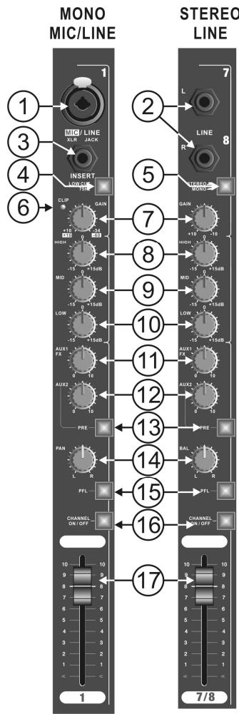
INPUT CHANNELS
-
COMBO INPUT:
-
MICROPHONE INPUT = 3 PIN FEMALE XLR CONNECTOR
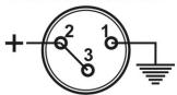
UNBALANCED MIC
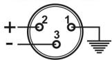
BALANCED MIC
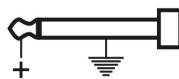
- MONO LINE INPUT = 1/4" JACK SOCKET
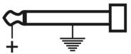
UNBALANCED LINE
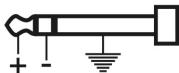
BALANCED LINE
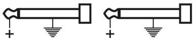
- 1 / 4'' JACK SOCKET LINE INPUTS
LINE:LEFTINPUT
LINE: RIGHT INPUT
- INSERT
Allows you to insert an external effect (like compressor, noise gate, equaliser, etc) that you will only use for this channel. Wiring 14 " Stereo Jack socket:

- LOW CUT FILTER Switch
When this button is lit, the frequencies below 75Hz for this channel will be filtered. This can be useful for example to avoid 'popping' of microphones or stage rumble.
- STEREO/MONO SWITCH
When this button is lit, the mono function is activated; the Left input signal will be send to the Left and Right channel
- CLIP LED
This warning will illuminate 4dB before clipping and will remain on for a short period. For optimal input channel running level, adjust Gain Control until Clip indicator illuminates while signal peaks are present. Then
adjust the gain setting until Clip indicator is off. This will give optimal signal to noise.
- GAIN CONTROL
Allows maximum input signal control and will accommodate most microphones of both low or high impedance to 600 Ohm as well as Phantom Power (48 Volt) types. The line input can be anything from keyboard through to line level feeds from other equipment.
Gain range:
XLR input +15 to +60dB
Jack input -15 to +30dB
- EQ CONTROL 'HIGH'
Allows 15dB cut/boost for the high frequencies (15kHz)
- EQ CONTROL 'MID'
Allows 15dB cut/boost for the mid frequencies (2,5kHz)
- EQ CONTROL 'LOW'
Allows 15dB cut/boost for the low frequencies (65Hz)
- AUX SEND 1 (Post-Fade)
This auxiliary send control is 'Post-fade' and is mainly used to send the signal of the channel to the internal effect module. When the AUX1/FX send (11) is used, the internal effect unit is switched off. The AUX1 send level changes with the position of the channel fader (17).
- AUX SEND 2 (Pre-Fade or Post-Fade)
This knob is used to send the audio signal of this channel to the AUX 2 SEND output. It can be switched pre or post fader. See next point (13) for more information
-
PRE-FADE / POST-FADE SWITCH for AUX SEND 2
-
Button is lit: AUX2 for this channel is switched PRE-FADE. The level is only influenced by the Gain control (7) and not by the channel fader (17). Use this setting for example when AUX2 is used to control stage monitors.
-
Button is not lit: AUX2 for this channel is switched POST-FADE. The level is also influenced by the position of the channel fader (17). Use this setting for example when AUX2 is used for external effect equipment.
-
PAN/BAL CONTROL
-
Pan control: also called "panoramic control" is used on the mono input channels to position the mono microphone somewhere left or right in the stereo output.
-
Balance control: is used to set the stereo balance of the stereo input channels.
-
PFL SWITCH
Also called "Pre Fade Listening" is used to monitor the input channel on the headphone while the channel fader is closed.
- CHANNEL ON/OFF BUTTON
This button is very useful if you want to cut the output of an input channel without changing the settings and levels. Switching off unused channels increases the signal/noise ratio of the mixer.
- ON button is lit: The channel is switched on
- ON button is not lit: the channel is switched off
- 60mm FADER
Controls the output signal of the corresponding input channel.
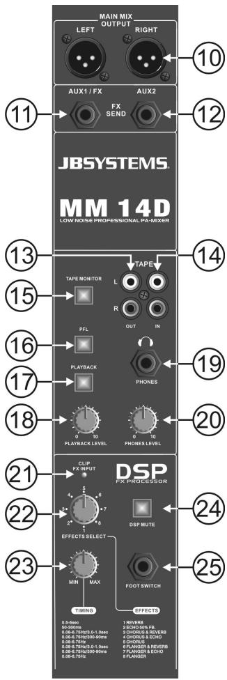
OUTPUT SECTION
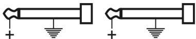
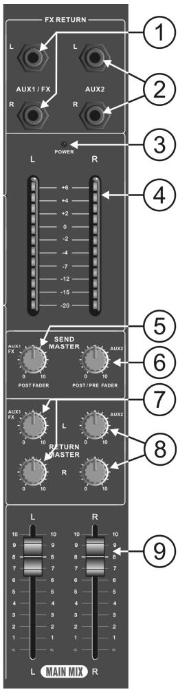
- AUX1 RETURN- 1/4" Jack Mono Socket Inputs
To inject the return signal from external effects back into the mixing console. When a jack is inserted, the internal DSP-effects are not used.
EFF RETURN: L. INPUT EFF RETURN: R. INPUT
- AUX2 RETURN- 1/4" Jack Mono Socket Input
Same function as Aux1 Return(1). Can also be used to connect an extra sound source (ex. CD player) to the mixing console.
EFF RETURN: L. INPUT EFF RETURN: R. INPUT
- POWERLED
This blue led is lit when the power is switched on. (the power switch is situated on the back of the mixing console)
- LED VU-METER
This is a 12 segment led meter with VU calibration providing a signal monitor range from -20dB to 6dB. with a change of colour at the nominal 0dB position.
- MASTER CONTROL FOR AUX1 SENDS
Used to set the general output level of the AUX1-signals, controlled by the AUX1 FX Sends (11) and sent to the internal or external effect processor.
- MASTER CONTROL FOR AUX2 SENDS
Used to set the general output level of the AUX2-signals, controlled by the AUX2 FX Sents (12) and sent to the external effect processor (post-fade) or to stage monitors (pre-fade).
- MASTER CONTROL FOR AUX1 RETURN
Used to mix the AUX1 return signal with the main output of the mixing console.
- MASTER CONTROL FOR AUX2 RETURN
Used to mix the AUX2 return signal with the main output of the mixing console.
- MASTER OUTPUT FADER CONTROL
Used to set the required overall output level to the power amplifier (or other equipment). The calibration shows a suggested nominal running level, referenced '0' (10dB boost is available if required).
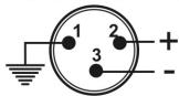
- STEREO MAIN MIX OUTPUT - 3 pin Male XLR Sockets
Used to connect the master output (Main mix) of the mixer to a power amplifier (or other equipment)
Output wiring:
UNBALANCED OUTPUT
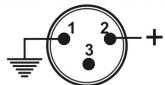
BALANCED OUTPUT
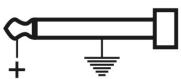
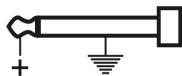
- AUX SEND OUTPUT - 1/4" Jack Mono Socket (unbalanced) output
Used to send the signal of AUX1 to external equipment or effect units.
Remark: When you insert a jack connector in the AUX1 SEND output, the internal effect unit will automatically be deactivated.
Output wiring:
EFFECT SEND: AUX1
- AUX SEND OUTPUT - 1/4" Jack Mono Socket (unbalanced) output
Used to send the signal of AUX2 to external equipment, effect units or stage monitors.
EFFECT SEND: AUX2
- TAPE OUT - stereo RCA Socket Outputs (unbalanced)
The signal is derived from the main stereo output mix after the output faders and can be used to record the master mix.
- TAPE IN - stereo RCA Socket Inputs (unbalanced)
Signal is routed to the main stereo output before the faders and the monitoring system.
- TAPE MONITOR SWITCH
Used to select which signal is routed to the PFL-switch (16):
- Switch ON (lit): signal from TAPE IN (14)
-
Switch OFF (not lit): signal from MAIN MIX. This is the same signal as on the TAPE OUT (13) and the MAIN MIX OUTPUT(10).
-
PFL SWITCH
Used to select which signal is routed to the HEADPHONE output(19):
- Switch ON (lit): PFL-signals of the input channels.
-
Switch OFF (not lit): signal is selected by the TAPE MONITOR switch(15).
-
PLAYBACK SWITCH
Used to add the stereo TAPE IN(14) signal to the main stereo output mix or not.
Used to set the playback level of the TAPE IN(14) signal.
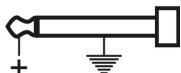
- HEADPHONE OUTPUT - 1/4" Stereo Jack Socket Output
Output wiring:

Minimum Load impedance: 40 Ohm
- HEADPHONE LEVEL CONTROL
Sets the level of the HEADPHONE output (19).
- DSP CLIP LED
This led blinks when the input signal of the internal DSP-effect processor is too high.
22.EFFECT SELECTOR KNOB
Used to select one of the 8 available digital effects.
- DSP TIMING KNOB
Used to adapt the selected effect to your personal taste.
- DSP MUTE
When this button is lit, the internal effect unit is switched off. This is very useful to compare your mix with and without effects.
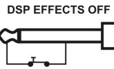
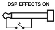
- FOOT SWITCH connector
Here you can connect a foot switch to switch the internal effects on/off.
Connector wiring:
REAR PANEL
26. POWER ON/OFF SWITCH
Used to switch the mixer on/off. We strongly advise to set the master output faders (9) of the mixer
and the gain controls of your amplifier to zero before you switch the mixer on or off.
27. POWER SUPPLY CONNECTOR
Connect the included power supply here. Replace this power supply only with exactly the same type number.
28. PHANTOM POWER SWITCH
This +48Vdc voltage should be used when condenser microphones are connected to the microphone inputs.
Attention:
- All XLR microphone inputs will carry the 48Vdc voltage when the phantom power is switched on. We strongly advice to check the user manual of the microphones before using the phantom power option.
- Make sure to switch the mixer off while using the phantom power switch(28)
- Normally you can still connect dynamic microphones while the phantom power is switched on, however to prevent unwanted damage we strongly insist you check the user manual of your dynamic microphone before using it.
SPECIFICATIONS
Power Supply: input: 230Vac,50Hz
output: 2x20Vac500mA
Frequency response: microphone: 20-20.000Hz +/-2dB
line input: 20-20.000Hz +/-1.5dB
THD + noise: microphone: <0.3% @ 1kHz, 0dB
line input: <0.05% @ 1kHz, 0dB
Tone controls: high freq. +/-15dB 15kHz
mid freq. +/-15dB 2,5kHz
low freq. +/-15dB65Hz
Micro inputs: 1mV @ 200-600 Ohm/balanced
Line inputs: 300mV @ 10kΩ
Record output: 775mV @ 50kΩ
Master output: 2V @600Ω
Dimensions: 483(W) x 355(H) x 78(D) mm
Weight (mixer): 5,4kg
Weight (power adapter): 0,85kg
Every information is subject to change without prior notice
You can download the latest version of this user manual on our website: www.beglec.com
MODE D'EMPLOI
9. EQ Controle 'MID'
10. EQ Controle 'LOW'
12. AUX SEND 2 (Pre-Fade of Post-Fade)
- FOOT SWITCH connector
mid freq. +/-15dB2,5kHz
lage freq. +/-15dB65Hz
S/N Ratio (IHF-A): >85dB Phantom voeding: +48Vdc
- AUX SEND 1 (Post-Fade)
- CHANNEL ON/OFF KNOPF
Hohe Freq. +/-15dB 15kHz
Mittlere Freq. +/-15dB 2,5kHz
Niedrige Freq. +/-15dB65Hz
85dB
+48V Gleichstrom
1mV @ 200-600 Ohm/ symmetrisch
300mV @ 10kΩ
775mV @ 50kΩ
2V @ 600Ω
483(B) x 355(H) x 78(T) mm
5,4kg
0,85kg
4. Interruptor LOW CUT FILTER
Frec. media +/-15dB2,5kHz
Freq.baja +/-15dB65Hz
Permite 15dB de corte/aumento as freque. Medias (2,5kHz)
10. CONTROLLO EQ 'LOW' - BAIXOS
Permite 15dB de corte/aumento as frequenc. Baixas (65Hz)
11. AUX SEND 1 (Post-Fade)
- CONECTOR FOOT SWITCH connector
Freq. alias +/-15dB 15kHz
Freq. Médias: +/-15dB 2,5kHz
Freq.Baixas: +/-15dB65Hz
Racio S/N(IHF-A):
85dB
+48Vdc
Phantom power:
1mV @ 200-600 Ohm/balanceada
Entrada micro:
300mV @ 10kΩ
Saía de Gravación:
775mV @ 50kΩ
Sáda Master:
2V @ 600Ω
Dimensoes:
483(W) x 355(H) x 78(D) mm
Peso (Mesa):
5,4kg