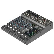
BEAT 4 - Audio Mixer JBSYSTEMS LIGHT - Free user manual and instructions
Find the device manual for free BEAT 4 JBSYSTEMS LIGHT in PDF.

| Brand | JBSYSTEMS LIGHT |
| Model | BEAT 4 |
| Product type | DJ audio mixer table |
| Power supply | AC 230 V, 50 Hz, 34 W |
| Dimensions (W x H x D) | 294 x 93 x 372 mm |
| Weight | 5.4 kg |
| Frequency response | 20 - 20,000 Hz (+/-3 dB) |
| Distortion (THD + noise) | <0.05% @ 1 kHz, 0 dB, load 47 kΩ |
| Signal-to-noise ratio | >78 dB (IHF-A) @ 1 kHz |
| Inputs | 7 line, 3 phono, 1 DJ mic (XLR), 2 bidirectional USB |
| Outputs | 2 Master (1 balanced XLR, 1 unbalanced), Record |
| USB connectivity | USB 2.0 bidirectional (44.1 kHz/16 bit), compatible with Windows & Mac OS |
| Tone control | 3-band (treble, mid, bass) with Kill function (-26 dB) |
| Crossfader | VCA type with adjustable curve, with Fader Start function |
| Channel faders | Replaceable DJ "steel rail" sliders |
| Talkover | Automatic attenuation of channels 2 to 4 while using the DJ mic |
| VU meters | LED on output stereo channels, mono for PFL signal |
| BPM counter | Automatic and accurate on selected channel |
| Pre-listening | PFL with Cue Mix option |
| Headphone output | 6.3 mm jack, 3 V @ 32 Ω |
| DJ mic input | Balanced XLR, 2 mV @ 3 kΩ, with talkover |
| Line/CD inputs | 340 mV @ 47 kΩ |
| Phono inputs | 3 mV @ 47 kΩ |
| Maintenance and cleaning | Clean with a slightly damp cloth; do not use abrasive liquids |
| Safety | Indoor use only; do not open; max. temperature 45°C; minimum ventilation 5 cm |
| Spare parts and repairability | User-replaceable sliders and crossfader; main fuse accessible |
Frequently Asked Questions - BEAT 4 JBSYSTEMS LIGHT
User questions about BEAT 4 JBSYSTEMS LIGHT
0 question about this device. Answer the ones you know or ask your own.
Ask a new question about this device
Download the instructions for your Audio Mixer in PDF format for free! Find your manual BEAT 4 - JBSYSTEMS LIGHT and take your electronic device back in hand. On this page are published all the documents necessary for the use of your device. BEAT 4 by JBSYSTEMS LIGHT.
USER MANUAL BEAT 4 JBSYSTEMS LIGHT
Copyright © 2009 by BEGLEC comm.v.a.
Reproduction or publication of the content in any manner, without express permission of the publisher, is prohibited.


EN - DISPOSAL OF THE DEVICE
Dispose of the unit and used batteries in an environment friendly manner according to your country regulations.
FR-DECLASSES L'APPAREIL
Thank you for buying this JB Systems® product. To take full advantage of all possibilities, please read these operating instructions very carefully.
FEATURES
This unit is radio-interference suppressed. This appliance meets the requirements of the current European and national guidelines. Conformity has been established and the relevant statements and documents have been deposited by the manufacturer.
- 13 inputs on 4 channels (7line, 3phones, 1micro, 2USB)
- 2 Bidirectional USB connections (play and record at the same time!)
- Completely redesigned for superior sound quality and very low noise
1 separate balanced DJ micro with talkover - Gain, high, mid, low controls with -26dB kill function on all channels
- Assignable and easy replaceable VCA-crossfader
Voltage controlled crossfader with adaptable fader curve - User replaceable easy gliding "steel rail" DJ faders
- 2 Master outputs (Master1 with balance control)
- Master1 with balanced XLR outputs
- Stereo LED VU-meters on master
- Mono LED VU-meter for PFL-signal
- Accurate automatic beat counters
Crossfader starts for compatible CD players - Pre-fade listening with cue mix option
BEFORE USE
- Before you start using this unit, please check if there's no transportation damage. Should there be any, do not use the device and consult your dealer first.
- Important: This device left our factory in perfect condition and well packaged. It is absolutely necessary for the user to strictly follow the safety instructions and warnings in this user manual. Any damage caused by mishandling is not subject to warranty. The dealer will not accept responsibility for any resulting defects or problems caused by disregarding this user manual.
- Keep this booklet in a safe place for future consultation. If you sell the fixture, be sure to add this user manual.
- To protect the environment, please try to recycle the packing material as much as possible.
Check the contents:
Check that the carton contains the following items:
- Mixer
- Mains cable
- Operating instructions
SAFETY INSTRUCTIONS:

CAUTION
RISK OF ELECTRIC SHOCK DO NOT OPEN

CAUTION: To reduce the risk of electric shock, do not remove the top cover. No user-serviceable parts inside. Refer servicing to qualified service personnel only.
The lightning flash with arrowhead symbol within the equilateral triangle is intended to alert the use or the presence of un-insulated "dangerous voltage" within the product's enclosure that may be of sufficient magnitude to constitute a risk of electric shock.

The exclamation point within the equilateral triangle is intended to alert the user to the presence of important operation and maintenance (servicing) instructions in the literature accompanying this appliance.
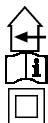
This symbol means: indoor use only
This symbol means: Read instructions
This symbol means: Safety Class II appliance
- To prevent fire or shock hazard, do not expose this appliance to rain or moisture.
- To avoid condensation to be formed inside, allow the unit to adapt to the surrounding temperatures when bringing it into a warm room after transport. Condense sometimes prevents the unit from working at full performance or may even cause damages.
- This unit is for indoor use only.
- Don't place metal objects or spill liquid inside the unit. No objects filled with liquids, such as vases, shall be placed on this appliance. Electric shock or malfunction may result. If a foreign object enters the unit, immediately disconnect the mains power.
- No naked flame sources, such as lighted candles, should be placed on the appliance.
- Don't cover any ventilation openings as this may result in overheating.
- Prevent use in dusty environments and clean the unit regularly.
- Keep the unit away from children.
- Inexperienced persons should not operate this device
Maximum save ambient temperature is 40^ . Don't use this unit at higher ambient temperatures. - Minimum distances around the apparatus for sufficient ventilation is 2cm .
- Always unplug the unit when it is not used for a longer time or before you start servicing.
- The electrical installation should be carried out by qualified personal only, according to the regulations for electrical and mechanical safety in your country.
- Check that the available voltage is not higher than the one stated on the rear panel of the unit.
- The socket inlet shall remain operable for disconnection from the mains.
- The power cord should always be in perfect condition. Switch the unit immediately off when the power cord is squashed or damaged. It must be replaced by the manufacturer, its service agent or similarly qualified persons in order to avoid a hazard.
- Never let the power-cord come into contact with other cables!
- When the power switch is in OFF position, this unit is not completely disconnected from the mains!
- In order to prevent electric shock, do not open the cover. Apart from the mains fuse there are no user serviceable parts inside.
- Never repair a fuse or bypass the fuse holder. Always replace a damaged fuse with a fuse of the same type and electrical specifications!
- In the event of serious operating problems, stop using the appliance and contact your dealer immediately
- Please use the original packing when the device is to be transported.
- Due to safety reasons it is prohibited to make unauthorized modifications to the unit.
INSTALLATION GUIDELINES:
- Install the unit in a well-ventilated location where it will not be exposed to high temperatures or humidity.
- Placing and using the unit for long periods near heat-generating sources such as amplifiers, spotlights, etc. will affect its performance and may even damage the unit.
- Attach the unit using the 4 screw holes on the front panel. Be sure to use screws of the appropriate size. (screws not provided) Take care to minimize shocks and vibrations during transport.
- When installed in a booth or flight case, please make sure to have good ventilation to improve heat evacuation of the unit.
- To avoid condensation to be formed inside, allow the unit to adapt to the surrounding temperatures when bringing it into a warm room after transport. Condense sometimes prevents the unit from working at full performance.
CLEANING THE MIXER:
Clean by wiping with a polished cloth slightly dipped with water. Avoid getting water inside the unit. Do not use volatile liquids such as benzene or thinner which will damage the unit.
CONNECTIONS
Except for microphones, headphone and master outputs, all connections are cinch. Use good quality cinch-cinch cables to prevent bad audio quality.
For more information on connections, please refer to the next chapter.
Be sure to turn off the mixer before you make changes to the different connections.
In this manual we talk about "line inputs". This is a global name for inputs with a level up to 2V. This includes tuners, videos, CD-players, etc.
Both USB connections will be detected as a sound card on your computer. These connections are bidirectional (play/record music simultaneously)
CONTROLS AND FUNCTIONS (FRONT)
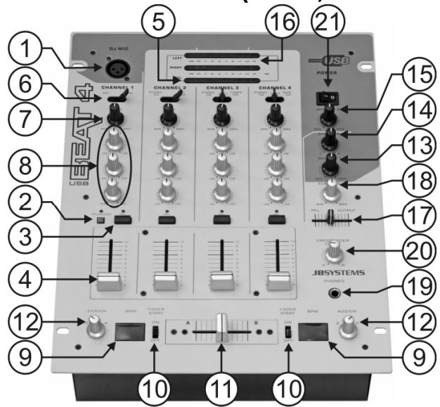
- DJ MIC INPUT: Accepts a balanced microphone with an XLR connector. This input is mainly used as DJ-microphone. The talk over does not affect the signal level of this input.
- TALKOVER: Use the switch to automatically mute the input channels 2 to 4 while you are talking through the DJ microphone.
- PFL SELECTOR: Used to select the source (CH-1 to CH-4) to be monitored via the headphones output. Pressing multiple Cue Buttons makes it possible to derive a mixed sound from the selected sources.
- CHANNEL FADER: Used to set the level of each channel separately. You can easily exchange this fader with a new one. Later in this manual we explain how to do this.
- PFL VU METERS: Monitors the level of the channel you selected with the PFL-switch (3). Make sure the levels do not exceed 0dB (or 100% ). The audio risks to be distorted when the signal level comes in the red zone of the VU-meter.
- INPUT SOURCE SELECTOR: Used to select the correct input on each channel: Phono, line, USB, aux or mic. On some channels there are additional input selectors on the back. Hint: Line, Aux, CD, Tuner, etc... are different names for inputs with almost the same signal levels.
- GAIN LEVEL: Adjusts the input level on each channel. Use this control to adjust the level on the VU-meter at about 0dB.
- 3-BAND TONE CONTROLS: The frequency of each channel can be controlled separately over a range from -26dB to +12dB. In the center position the tone control is flat. (switched off)
-
BEAT COUNTER DISPLAY: Shows the number of beat per minute (BPM) of the music on the channel selected with the crossfader assign selector (12). To have a reliable result on the display the music must have a clear and steady beat.
-
FADER START ON/OFF SWITCH: When you have a compatible CD-player connected to the fader control connectors, you can control its start/stop (re-cue) functions with the cross fader. With this switch you can turn the fader start control on and off.
- CROSSFADER: With this VCA fader you can mix over between the channels you selected with the crossfader assign selectors (12). The crossfader only works when you move the selected channel faders (4) to the desired level! The crossfader also integrates the optical fader starts. See the next chapter for more information on this issue.
- CROSSFADER ASSIGN: Selects the input channels to be used with the crossfader (11) and beat counters (9). When set to "0" the crossfader is switched off.
- MASTER1 LEVEL: Used to adjust the level of the balanced Master1 output.
- BALANCE MASTER1: used to adjust the balance between left and right output on Master1.
- MASTER2 LEVEL: Used to adjust the level of the unbalanced Master2 output.
- MASTER1 VU METERS: Monitors the output level of master1. Make sure the levels do not exceed 0dB (or 100% ). The audio will be distorted when the signal level comes in the red zone of the VU-meter.
-
CUE MIX: With this fader you can mix the master output and any of the input channels through the headphone output (19):
-
Put the fader in the extreme left position to monitor a selected PFL signal (3).
- Put the fader in the extreme right position to hear the master output.
-
Put the fader in any other position to hear a mix of the two signals.
This option makes it possible to check your mix before you put it on the master output. -
CUE LEVEL: Used to control the output level of the headphone output.
-
HEADPHONE JACK: You can monitor all inputs/outputs when you connect any modern stereo headphone to this 6.3mm jack.
- CROSS FADER CURVE: Adjusts the curve of the cross fader from smooth (left position) to sharp (right position).
- POWER SWITCH: Used to turn the power of the mixer on and off. The blue led is lit when the mixer is turned on.
CONTROLS AND FUNCTIONS (rear)
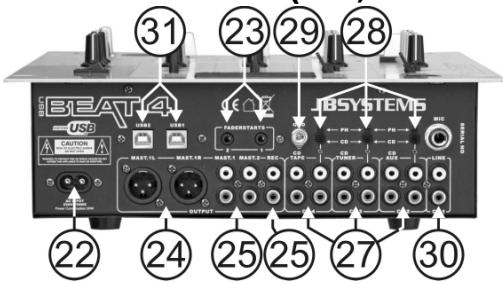
- MAINS CABLE: connect this cable to a 230V/50Hz mains outlet. Before use, inspect the cable to be sure it's not damaged!
- FADER CONTROL: When connected to these inputs, compatible CD-players can be controlled by the fader starts of this mixer.
- MASTER1 BALANCED OUTPUT: The XLR-connectors can be used to connect this mixer to any balanced amplifier input, using special balanced signal cables.
- MASTER UNBALANCED OUTPUTS: The "master 1" output has the same output signal as the balanced master output(24) but unbalanced. The "master 2" output carries the same signal but can be controlled independently by the master2 level (15). Use the outputs to connect unbalanced amplifiers.
- RECORD OUTPUT: Carries the same signal as the master outputs but is not influenced by the master level and balance controls. Used to connect analog recording equipment. You can also connect a computer for direct digital recording, see USB connections (34).
- INPUT CHANNELS: each used to connect two different line level audio signals. Refer to switch (28) to change one line input to phono level. The input source selector (6) on the front determines which input will be active.
-
PHONO/CD SWITCH: This switch makes it possible to switch between the CD and phono level inputs on channels 2, 3 and 4.
-
GROUND (GND) CONNECTION: Many Turntables have a GND-connection. It is preferable to connect this signal ground to the GND-connector. If your turntable does not have a ground wire, you don't have to use this connector.
- INPUT CHANNEL 1: used to connect a DJ microphone and/or a line level audio signal. The input source selector (6) on the front determines which input will be active.
- USB CONNECTIONs: two bidirectional USB connections (USB1 for CH3 ~ USB2 for CH4). You can connect any PC through these USB connections. The PC/Mac will detect your mixer as a sound card, normally no drivers are needed. Since both USB ports are bidirectional you are able to play music on your computer and mix this music with other sources like CD, phono, etc. At the same time you can record your mix on your computer with the same USB connection!
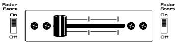
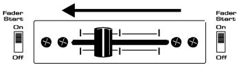
CROSSFADER STARTS
The crossfader integrates the optical fader start switches. These fader starts are compatible with all current JB Systems CD-players. This is how it works:
A. CROSSFADER IN LEFT POSITION:
CD-player connected to fader start connector A is playing, the other CD-player is paused.
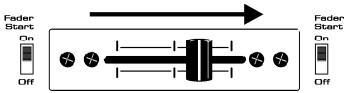
B. CROSSFADER MOVES TO THE RIGHT:
CD-player connected to fader start connector A stops playing, returns to its previously programmed cue point and waits in pause. The other CD-player starts playing from its previously programmed cue point.
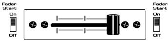
C. CROSSFADER IN RIGHT POSITION:
CD-player connected to fader start connector B is playing, the other CD-player is paused.
D. CROSSFADER MOVES TO THE LEFT:
CD-player connected to fader start connector B stops playing, returns to its previously programmed cue point and waits in pause. The other CD-player starts playing from its previously programmed cue point.
Important: Both fader start switches must be in "ON" position!


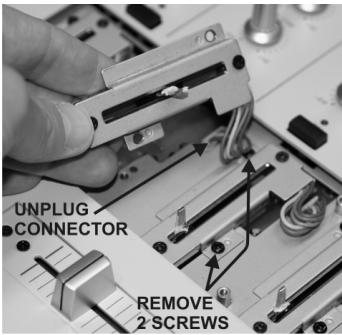
CHANGING THE FADERS
One of the big advantages of this mixer is the possibility to change the channel faders
This is what you must do to change a channel fader:
- Remove the fader knobs from the faders.
- Remove the 4 screws that hold the small front panel around the faders.
- Remove the 2 screws of the fader you want to change.
- Gently remove the fader from its position and unplug the connector from the main board. (do NOT pull the cable!)
- Put the new fader gently in place. Be sure to plug the connector in the connector base on the mixer PCB-board.
- Put the 2 screws from the fader back in place
- Put the small front plate back in place with the 4 screws.
Done!
This is what you must do to change the cross fader:
- Remove the fader knob from the cross fader.
- Remove the 2 screws that keep the cross fader in place.
- Gently remove the fader and the cover plate from their position.
- Unplug the cross fader from the cable (unplug the cable by pulling the connector, NOT the cable!)
- Press the new cross fader on the cable.
- Put the cross fader back in place with the small cover plate and the 2 screws.
Done!
SPECIFICATIONS
Power Supply: AC 230 V, 50Hz (34Watt)
Frequency response: 20-20.000Hz (+/-3dB)
THD + noise: <0.05% @ 1kHz, 0dB, load = 47kΩ
S/N Ratio (IHF-A): >78dB @ 1kHz.
USB connections: USB 2.0, bidirectional (44,1kHz / 16bit)
Windows® & MacOS® compatible.
USB cable (not included): Lmax = 3m
Mic inputs:
Line/CD inputs: 340mV @ 47kΩ
Phono inputs: 3mV @ 47kΩ
Record output: 775mV @ 1kΩ
Master 1/2 output: 1.55V @ 1kΩ unbal.
Master 1 output: 2,55V @ 600Ω bal.
Talkover:
Channel tone controls:
Headphone:
Dimensions:
Weight:
Every information is subject to change without prior notice
You can download the latest version of this user manual on our website: www.beglec.com
MODE D'EMPLOI
<0.05% @ 1 kHz, 0 dB, cargo = 47 kΩ
78 dB @ 1 kHz.
USB 2.0, bidirectional (44,1 kHz / 16 bit)
Windows® & MacOS® compatible.
L_ = 3m
+12dB / -26dB (70 Hz, 1 kHz, 13 kHz)
3V @32Ω
294(A) × 372( P) × 93( A)
5,4 kg