
LED MANAGER - LED power supply JBSYSTEMS LIGHT - Free user manual and instructions
Find the device manual for free LED MANAGER JBSYSTEMS LIGHT in PDF.

| Product type | LED power supply for passive RGB projectors |
| Brand | JBSYSTEMS LIGHT |
| Model | LED MANAGER |
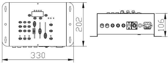
| Dimensions (L x W x H) | 330 x 202 x 106 cm |
| Weight | 6.6 kg |
| Mains power | AC 230 V, 50 Hz |
| LED output voltage | DC 24 V, common anode |
| Maximum output power | 300 W (2 x 150 W), split over 2 cables |
| Power per color | Red: 100 W max, Green: 100 W max, Blue: 100 W max |
| Fuses | 3 x 6.3 A slow blow (20 mm glass) |
| Backup battery | 3 x AA NiMH rechargeable (optional) |
| DMX connection | XLR 3-pin (input and output) |
| DMX channels | 4 (CH1: red, CH2: green, CH3: blue, CH4: dimmer/strobe) |
| Main functions | Fixed colors (9 colors), Chase mode (12 chases), Spectrum mix (32 colors), Sound chase, Black-out, Full on, Programmable timers (3), 24h clock, Master/Slave mode, Remote control LEDCON-01 |
| Settings | Chase/Color slider, Speed/Fade slider, Master slider (dimmer/strobe) |
| Display | 4-digit LED display, Status LEDs (DMX, Master, Slave, Sound) |
| Audio input | Internal microphone (for Sound chase mode) |
| Installation | Wall mountable (mounting holes), internal fan |
| Max. ambient temperature | 45 °C |
| Maintenance and cleaning | Clean with a slightly damp soft cloth; annual internal cleaning by a qualified person |
| Safety | Do not open, short-circuit protection, indoor use only, disconnect before maintenance |
| Spare parts and repairability | Replaceable 6.3 A slow blow fuses; rechargeable NiMH backup batteries; no other user-serviceable parts |
| General information | Versatile power supply for passive RGB LED projectors, DMX512 compatible, usable standalone or master/slave, clock with backup |
Frequently Asked Questions - LED MANAGER JBSYSTEMS LIGHT
User questions about LED MANAGER JBSYSTEMS LIGHT
0 question about this device. Answer the ones you know or ask your own.
Ask a new question about this device
Download the instructions for your LED power supply in PDF format for free! Find your manual LED MANAGER - JBSYSTEMS LIGHT and take your electronic device back in hand. On this page are published all the documents necessary for the use of your device. LED MANAGER by JBSYSTEMS LIGHT.
USER MANUAL LED MANAGER JBSYSTEMS LIGHT
Copyright © 2006 - 2007 by BEGLEC cva.
Reproduction or publication of the content in any manner, without express permission of the publisher, is prohibited.

Version: 1.2


EN - DISPOSAL OF THE DEVICE
Dispose of the unit and used batteries in an environment friendly manner according to your country regulations.
FR-DECLASSES L'APPAREIL
Thank you for buying this JB Systems product. To take full advantage of all possibilities, please read these operating instructions very carefully.
FEATURES
This unit is radio-interference suppressed. This product meets the requirements of the current European and national guidelines. Conformity has been established and the relevant statements and documents have been deposited by the manufacturer.
-
Extremely versatile power supply for all kinds of passive RGB LED-projectors.
-
Different standalone working modes:
-
Fixed color mode: Instant access to 9 pre-programmed colors
- Static chase mode: 12 different color chases with manual speed control
Sound chase mode: 12 different color chases with audio triggering -
Spectrum mix: 32 different spectrum mix colors, including nice color fades
-
Adjustable speed and dimming with faders
- Slow color fades with adjustable fade time
- Blackout and "Full on" function
- All functions can be controlled directly on the on the LED-Manager or by the optional LEDCON-01 remote.
- Several LED-Managers can be used in Master/slave mode to create high power, fully synchronized setups.
- 300Watt power: 2x 150W 24Vdc outputs. (R + G + B) with short-circuit protections
- Built-in Clock with battery backup and NiMH battery charger (batteries not included)
- 3 independent programmable on/off timers. (start/stop 3 different color chases at 3 different times!)
- Can be controlled by any standard DMX controller!
- 4 DMX channels needed: Ch1=red, Ch2=green, Ch3=Blue, Ch4=Dimmer/strobe.
- Enclosure prepared for easy installing against the wall.
- Fan cooling for extra reliability.
BEFORE USE
Check the contents:
Check that the carton contains the following items:
- LED-Manager
- Mains cable
- User manual
Some important instructions:
- Before you start using this unit, please check if there's no transportation damage. Should there be any, do not use the device and consult your dealer first.
- Important: This device left our factory in perfect condition and well packaged. It is absolutely necessary for the user to strictly follow the safety instructions and warnings in this user manual. Any damage caused by mishandling is not subject to warranty. The dealer will not accept responsibility for any resulting defects or problems caused by disregarding this user manual.
- Keep this booklet in a safe place for future consultation. If you sell the fixture, be sure to add this user manual.
- To protect the environment, please try to recycle the packing material as much as possible.
SAFETY INSTRUCTIONS:

CAUTION
RISK OF ELECTRIC SHOCK
DO NOT OPEN

CAUTION: To reduce the risk of electric shock, do not remove the top cover. No user-serviceable parts inside. Refer servicing to qualified service personnel only.

The lightning flash with arrowhead symbol within the equilateral triangle is intended to alert the use or the presence of un-insulated "dangerous voltage" within the product's enclosure that may be of sufficient magnitude to constitute a risk of electric shock.

The exclamation point within the equilateral triangle is intended to alert the user to the presence of important operation and maintenance (servicing) instructions in the literature accompanying this appliance.

This symbol means: indoor use only.
- To prevent fire or shock hazard, do not expose this appliance to rain or moisture.
- To avoid condensation to be formed inside, allow the unit to adapt to the surrounding temperatures when bringing it into a warm room after transport. Condense sometimes prevents the unit from working at full performance or may even cause damages.
- This unit is for indoor use only.
- Don't place metal objects or spill liquid inside the unit. No objects filled with liquids, such as vases, shall be placed on this appliance. Electric shock or malfunction may result. If a foreign object enters the unit, immediately disconnect the mains power.
- No naked flame sources, such as lighted candles, should be placed on the appliance.
- Don't cover any ventilation openings as this may result in overheating.
- Prevent use in dusty environments and clean the unit regularly.
- Keep the unit away from children.
- Inexperienced persons should not operate this device.
Maximum save ambient temperature is 45^ . Don't use this unit at higher ambient temperatures. - Always unplug the unit when it is not used for a longer time or before you start servicing.
- The electrical installation should be carried out by qualified personal only, according to the regulations for electrical and mechanical safety in your country.
- Check that the available voltage is not higher than the one stated on the rear panel of the unit.
- The socket inlet shall remain operable for disconnection from the mains.
- The power cord should always be in perfect condition: switch the unit immediately off when the power cord is squashed or damaged.
- Never let the power-cord come into contact with other cables!
- In order to prevent electric shock, do not open the cover. Apart from the mains fuse there are no user serviceable parts inside.
- Never repair a fuse or bypass the fuse holder. Always replace a damaged fuse with a fuse of the same type and electrical specifications!
- In the event of serious operating problems, stop using the appliance and contact your dealer immediately.
- Please use the original packing when the device is to be transported.
- Due to safety reasons it is prohibited to make unauthorized modifications to the unit.
MAINTENANCE
- Clean by wiping with a polished cloth slightly dipped with water. Avoid getting water inside the unit. Do not use volatile liquids such as benzene or thinner which will damage the unit.
- Since this unit uses a cooling fan, the interior of the device should be cleaned annually using a vacuum cleaner or air-jet.
Attention: We strongly recommend internal cleaning to be carried out by qualified personnel!
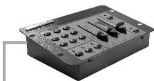
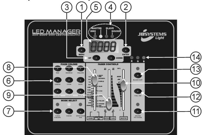
FUNCTIONS (FRONT)
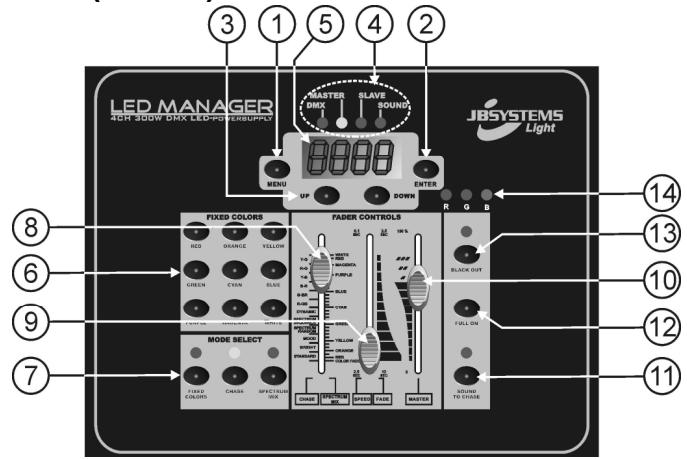
- MENU BUTTON: used to enter/leave the main menu. To return from the main menu to clock display just press the menu button for 1second.
- ENTER BUTTON: used to confirm your choice in the menu.
- UP/DOWN BUTTONS: used to browse through the main menu and adapt the values of a function.
-
STATUS MONITOR: indicates some important working conditions:
-
DMX-LED: indicates that the unit is working in DMX mode. (a DMX-signal is detected)
- MASTER LED: indicates that the unit is working in master mode.
- SLAVE LED: indicates that the unit is working in slave mode.
-
SOUND LED: indicates that a music signal is picked up by the internal microphone.
-
DISPLAY: 4digit LED display shows different menu options and real-time clock.
- FIXED COLOR BUTTONS: 9 buttons each with a preset color.
-
MODE SELECT BUTTONS: 3 buttons used to set the controller in different working modes:
-
FIXED COLORS: select this mode if you want to use the "fixed color" buttons (6).
- CHASE MODE: select this mode if you want to select one of the 12 color chases using the "chase/color" fader (8).
-
SPECTRUM MIX: select this mode if you want to select one of the 32 different colors using the "chase/color" fader (8).
-
CHASE/COLOR FADER: used to select one of the available color chases:
-
Left side of the fader indicates the different chases.
- Right side of the fader indicates the different colors.
-
Important remark: There's also a function called "color fade" which is very nice for "background lighting" applications. Select this function to fade gently from one color to another. You can adjust the fade-over time with the speed/fade fader(9).
-
SPEED/FADE FADER: used to select the chase speed or color fade time:
-
Left side of the fader indicates the chase speed, ranging from 2,5s to 0,1s.
-
Right side of the fader indicates the color fade time, ranging from 12s to 2,5s.
-
MASTER FADER: used to control the overall dimming of the LEDs and overall strobe speed.
-
SOUND BUTTON: used to toggle the chase mode between sound and static mode.
- FULL ON BUTTON: used to set the 3 colors (R + G + B) at maximum level.
- BLACKOUT BUTTON: used to set the 3 colors (R + G + B) at zero level.
- OUTPUT MONITOR: indicates the output levels for the 3 colors (R + G + B)
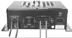
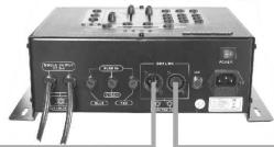
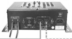
FUNCTIONS (REAR)
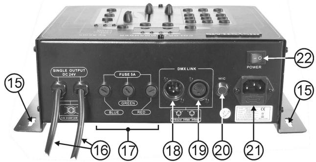
- FIXING HOLES: used to fix the unit on a wall or other flat surface.
- OUTPUT CABLES: used to connect different 24Vdc common anode LED projectors. (max. load: 300W) Each cable uses a special 4pin female connector.
- OUTPUT FUSES: 6,3A fuses on each of the 3 color outputs.
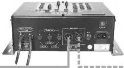
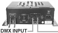
- DMX INPUT: 3pin male XLR-connector used to connect universal DMX-cables. This input receives instructions from a DMX-controller or from another LED-Manager when used in master/slave mode.
- DMX OUTPUT: 3pin female XLR-connector used to connect the LED-Manager with the next DMX appliance in the chain or with another LED-Manager when used in master/slave mode.
- INTERNAL MICRO: used for sound activated chases.
- MAINS INPUT: with IEC socket and integrated fuse holder, connect the supplied mains cable here.
- ON/OFF SWITCH: used to switch the unit on/off.
ELECTRICAL INSTALLATION
The electrical installation should be carried out by qualified personal only, according to the regulations for electrical and mechanical safety in your country.
How to connect the LED-projectors to the outputs of the unit:
Important: Switch the LED-manager OFF before you install the LED-projectors! The maximum total load of the LED Manager is 300W, spread over 3 colors: each of the 3 colors has a max. load of 100W! The total load is distributed over the 2 output cables. This means that each output cable supports 150W (max. 50W for each color!) to have a total maximum load of 300Watt. Make sure not to overload one of the output cables!
The 2 output cables (16) use a special 4pin connector. Two different types of passive LED projectors can be connected:
A. LED Projectors with a special 4pin connector (ex. LED STRIP):
This is the easiest way tomake the connections. Fixall projectors properly anddaisy chain their in/outputcables until you reach the
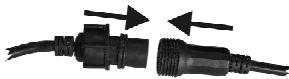
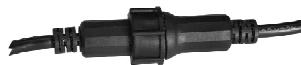
WELL CONNECTED
maximum allowed load. Make sure to fasten the plastic ring of the connector.
Example: you can connect up to fifteen "1m LED STRIP" on each output cable (total = 30m!)
B. LED Projectors with open wires (ex. LED GROUND LIGHT):
In this case we suggest to take a 1m extension cable (with special male/female 4pin connectors) and to cut the female connector. Now you can easily strip the cable. You will find 4 colored wires inside:
- Whitewire: This is the common wire (anode)
- Red wire: This the power for the red LEDs (max. 50W)
- Greenwire: This the power for the green LEDs (max. 50W)
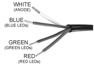
- Blue wire: This the power for the blue LEDs (max. 50W)
Just connect these 4 wires to the corresponding 4 wires of the projector. (in most cases the colors of the wires match with the LED colors) Make sure not to exceed the maximum allowed load!
Example: you can connect up to 50 "GROUND LIGHT" on each output cable (total = 100pcs!)
Electrical installation in Master/slave-mode:
- You need to "daisy chain" the DMX in/outputs of 2 or more units with a good quality balanced cable (ex. JB Systems ref. 7-0063).
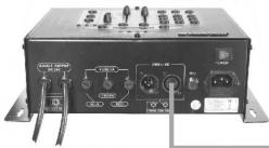
MASTER
SLAVE 1
SLAVE 2
- The unit with a free DMX-input connector automatically becomes the master (master LED is lit), the other units are automatically switched as slaves (slave LED is lit). The controls on the slave units are disabled.
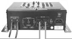
Electrical installation in Master/slave-mode with the LEDCON-01 remote:
- You need to "daisy chain" the DMX in/outputs of 1 or more units with the output of the LEDCON-01 remote using a good quality balanced cable (ex. JB Systems ref. 7-0063).
SLAVE 1
SLAVE 2
- The LEDCON-01 remote will be used to control all connected slaves. The LED Managers are automatically switched as slaves (slave LED is lit). The controls on the slave units are disabled.
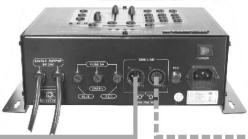
Electrical installation in DMX-mode:
- The DMX-protocol is a widely used high speed signal to control intelligent light equipment. You need to "daisy chain" your DMX controller and all the connected units with a good quality balanced cable (ex. JB Systems ref. 7-0063).
UNIT1
UNIT 2
UNIT 3
- To prevent strange behavior of the light effects, due to interferences, you must use a 90 to 120 terminator at the end of the chain. Never use Y-splitter cables, this simply won't work!
- Each unit in the chain needs its proper start address so it knows which commands from the DMX-controller it has to decode. When you need a lot of power you can use several LED managers and give them the same start address. In the next chap to set the DMX addresses.
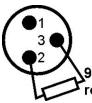
0~120 ohm
resistor
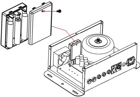
Changing the internal batteries:
VERY IMPORTANT: ONLY rechargeable batteries are allowed, do NOT use normal batteries!!!
The LED Manager has an internal real-time 24H clock with 3 individual timers and battery backup. To use the battery backup feature you must install 3 optional AA-type NiMH rechargeable batteries. Once these batteries are installed they will be recharged automatically, no need to replace them anymore!
- Switch the unit off and disconnect the mains cable.
- Use an appropriate screwdriver to unscrew the 10 screws of the enclosure.
- Gently remove the top cover (careful for the cables inside!)
- On the inside you will find a battery compartment, next to the fan. Open it gently and install the 3 AA-type NiMH rechargeable batteries as indicated.
- Close the battery compartment
- Put the top cover back in place and fasten the 10 screws.
- Connect the unit to the mains: the batteries will charge automatically.
- Done!
SETUP MENUS + DMX ADDRESSING
During normal operation the display shows the current time of the internal 24H clock.
- Press the MENU button to enter menu mode:
- With the UP and DOWN buttons you can browse through the different options of the main menu.
- Press the ENTER button to select and edit a menu option.
- Adapt the values with the UP & DOWN buttons and confirm with the ENTER button or press the MENU button again if you want to return to the main menu without saving the changes you just made.
- After some time the display will automatically show the internal clock. You can also switch to the clock display by pressing the MENU button for about 1 second.

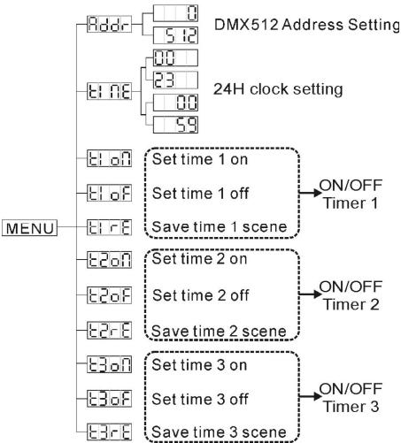
DMX start address setting
Used to set the start address of the LED Manager.
-
Once the correct address is shown on the display, press the ENTER button to save it.
-
Press the MENU button and UP/DOWN buttons until the display shows "Addr"
- Press the ENTER button: the display starts blinking.
- Use the DOWN and UP buttons to change the DMX address.
Remarks: You can abort the setting procedure and go back without saving the changes by shortly, pressing the MENU button. When the setup is done and changes are saved, you can return to the clock display by pressing the MENU button for more than 1 second.

Internal 24H clock setting
Used to set the time of the internal 24H clock.
- Press the MENU button and UP/DOWN buttons until the display shows "time"
- Press the ENTER button, the HOUR-display starts blinking.
- Use the DOWN and UP buttons to set the correct hours (00 to 23).
- Press the ENTER button, the MINUTE-display starts blinking.
- Use the DOWN and UP buttons to set the correct minutes (00 to 59).
- Once the correct time is shown, press the ENTER button. The new clock settings are saved while the display shows "time"
Remarks: You can abort the setting procedure and go back without saving the changes by shortly pressing the MENU button. When the setup is done and changes are saved, you can return to the clock display by pressing the MENU button for more than 1second.
Eon E20n E30n ON/OFF Timers "START-time" setting
The LED Manager has 3 individual ON/OFF timers. So you are able to switch the output on/off at 3 different parts of the day, each time with a different color or color chase. Below we explain how to set the start-time for "ON/OFF timer1". The settings for the other 2 timers are identical.
- Press the MENU button and UP/DOWN buttons until the display shows "t1on"
- Press the ENTER button, the HOUR-display starts blinking.
- Use the DOWN and UP buttons to set the correct hours (00 to 23).
- Press the ENTER button, the MINUTE-display starts blinking.
- Use the DOWN and UP buttons to set the correct minutes (00 to 59).
- Once the correct start time is shown, press the ENTER button. The new start time is saved while the display shows "t1on"
Remarks: You can abort the setting procedure and go back without saving the changes by shortly pressing the MENU button. When the setup is done and changes are saved, you can return to the clock display by pressing the MENU button for more than 1 second.
10 OF 20F 30F ON/OFF Timer "STOP-time" setting
Below we explain how to set the stop-time for "ON/OFF timer1". The settings for the other 2 timers are identical.
- Press the MENU button and UP/DOWN buttons until the display shows "t1oF"
- Press the ENTER button, the HOUR-display starts blinking.
- Use the DOWN and UP buttons to set the correct hours (00 to 23).
- Press the ENTER button, the MINUTE-display starts blinking.
- Use the DOWN and UP buttons to set the correct minutes (00 to 59).
- Once the correct stop time is shown, press the ENTER button. The new stop time is saved while the display shows "t1oF"
Remarks: You can abort the setting procedure and go back without saving the changes by shortly pressing the MENU button. When the setup is done and changes are saved, you can return to the clock display by pressing the MENU button for more than 1second.
E1-8E2R8E3C ON/OFF Timer "SCENE" setting
Below we explain how to select the scene (color or color chase) for "ON/OFF timer1". The settings for the other 2 timers are identical.
- Press the MENU button and UP/DOWN buttons until the display shows "t1rE"
- Press the ENTER button, the display starts blinking.
- Now you have the time to set the scene that you would like to reproduce when the timer is activated.
- When the scene is OK (don't forget to switch the blackout function off!) just press the ENTER button again. The display stops blinking and the scene is saved.
Remarks: You can abort the setting procedure and go back without saving the changes by shortly pressing the MENU button. When the setup is done and changes are saved, you can return to the clock display by pressing the MENU button for more than 1second.
OPERATING INSTRUCTIONS
A. Standalone 1unit:
- Connect the LED projectors to the LED Manager as indicated in the previous chapters. (no need to set a DMX address!)
- Switch the unit on and refer to the chapter "Functions" to make yourself familiar with the various functions of the faders and buttons.
In this mode you can also set the clock and use the 3 on/off timers as described in the previous chapter.
Remark: When a timer is active, you can deactivate it by pressing the blackout button.
B. Two or more units in master/slave setup:
- Connect the LED projectors to the LED Managers as indicated in the previous chapters.
- Connect the units with each other as explained in the chapter about electrical installations. (no need to set a DMX address!)
- Switch the LED Managers on. You can only use the controls on the master unit, the controls on the slaves are disabled. Refer to the chapter "Functions" to make yourself familiar with the various functions of the faders and buttons on the master unit.
In this mode you can also set the clock and use the 3 on/off timers on the master as described in the previous chapter.
Remark: When a timer is active, you can deactivate it by pressing the blackoutbutton.
C. Connect the optional LEDCON-01 controller for remote control:
In most cases the LED MANAGER will be installed on a wall, close to the LED-projectors. If you want to have easy access to its functions, you can connect the LEDCON-01 remote controller to the (first) LED Manager. The other connections are identical to those of the standalone or master/slave setups.
Except for the display, internal 24H clock and the 3 on/off timers, the controls on the remote are identical to that of the LED Manager. So please refer to the chapter "Functions" to make yourself familiar with the various functions of the faders and buttons.
D. Controlled by universal DMX-controller:
- Connect the LED projectors to the LED Manager(s) as indicated in the previous chapters.
- Connect the LED Manager(s) with all other DMX-appliances in the DMX-chain.
- Switch all units on and set the proper DMX-addresses. (DMX-LED on the LED Manager is lit)
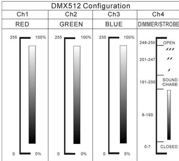
- Switch your universal DMX-controller on and refer to the DMX chart below to control the connected LED managers:
All controls (buttons and faders) on the LED Manager(s) are disabled, except the buttons needed to set the DMX-address.
SPECIFICATIONS
Power Input: AC 230V~50Hz
Fuse: 6,3A slow blow (20mm glass)
Backup batteries: 3x 1,2V AA-type NiMH rechargeable batteries (optional)
Output voltage to LEDs: DC 24V common anode
Output power to LEDs: 2x 150W max. (Total = 300W max.)
Red: 2x 50W max. (Total = 100W max.)
Green: 2x 50W max. (Total = 100W max.)
Blue: 2x 50W max. (Total = 100W max.)
DMX connections: 3pin XLR (DMX-512 standard)
DMX channels: 4 (CH1: red, CH2: green, CH3:blue, CH4:dimmer/strobe)
Audio input: None, internal microphone
Size: 330 × 202 × 106cm (see drawing below)
Weight: 6,6kg
Every information is subject to change without prior notice
You can download the latest version of this user manual on our website: www.beglec.com
MODE D'EMPLOI
FONCTIONS (FACE AVANT)
on 2019 2020 ON/OFF Timers "START-time" instilling
E E E E E E E ON/OFF Timer "SCENE"installing
DMX-Anschlüsse: 3-poliger XLR (DMX-512 Standard)
2x 150W max. (Total = 300W max.)
Rojo: 2x 50W max. (Total = 100W max.)
Verde: 2 × 50W . (Total = 100W max.)
Azul: 2x 50W max. (Total = 100W max.)
Conexiones DMX:
3pin XLR (DMX-512 estandar)
Canales DMX:
Ligaoes DMX: XLR 3 pinos (DMX-512 standard)
Canais DMX: 4 (CH1: vermelho, CH2: verde, CH3:azul, CH4:dimmer/strobe)