
EAA - Welding machine FESTOOL - Free user manual and instructions
Find the device manual for free EAA FESTOOL in PDF.
| Product type | Power supply satellite |
| Brand | Festool |
| Model | EAA |
| Category | Welding machine (according to classification) |
| Power supply | 220-240 V ~ 16 A, 50/60 Hz |
| Compressed air pressure | 4-8 bar (recommended 6 bar) |
| Weight (depending on variant) | 10.2 kg to 13.8 kg |
| Number of electrical outlets | 3 (1 permanent, 2 automatic) |
| Compressed air connections | 1 to 3 depending on variant (lubricated/non-lubricated) |
| Suction connection | Yes, for dust (diameter 50 mm) |
| Maximum tool holder load | 12 kg |
| Ambient temperature | 0 °C to 50 °C |
| Ambient humidity | Max 80% |
| Possible mounting | Wall, ceiling, Festool ASA suction arm |
| Available variants | EW, EW/DW, CT/SRM, TURBO, etc. |
| Main functions | Electrical and pneumatic supply, integrated suction |
| Maintenance and cleaning | Drain condensate, adjust oiler, check cables |
| Safety | Strain relief, grounding, overload protection |
| Warranty | 12 months minimum, 24 months EU |
| Included accessories (example) | Wall or ceiling mounting kit depending on variant |
| Required compressed air flow | Min. 400 l/min per pneumatic tool |
Frequently Asked Questions - EAA FESTOOL
User questions about EAA FESTOOL
0 question about this device. Answer the ones you know or ask your own.
Ask a new question about this device
Download the instructions for your Welding machine in PDF format for free! Find your manual EAA - FESTOOL and take your electronic device back in hand. On this page are published all the documents necessary for the use of your device. EAA by FESTOOL.
USER MANUAL EAA FESTOOL
Original operating manual
1 Symbols 18
2 Technical data 18
3 Intended use. 18
4 Safety instructions 19
5 Machine features 19
6 Design 19
6.1 Energy box 19
6.2 Versions 19
6.3 Conversion kits 20
7 Assembly 20
7.1 Attachment to Festool boom arm 20
7.2 Wall mounting 21
7.3 Ceiling installation 21
8 Connections in the EAA 22
8.1 Connecting the control cable..... 22
8.2 Connecting the mains cable..... 22
8.3 Connecting the compressed air line 22
8.4 Mounting the hose holder 22
9 Connecting the dust extractor..... 22
9.1 Mobile dust extractor 23
9.2 Stationary extraction system TURBO 23
10 Power supply. 23
10.1 Power 23
10.2 Compressed air 23
11 Operation 24
11.1 Switch on/off 24
11.2 Connecting pneumatic tools.... 24
11.3 Tool holder 24
11.4 Dust extraction 25
12 Service and maintenance 25
12.1 Adjusting the lubricator 25
13 Disposal 25
14 Troubleshooting 26
15 Accessories 26
16 Warranty 27
17 EU Declaration of Conformity..... 27
18 Circuit diagram parts list. 28
19 Pneumatics diagram parts list..... 28
The illustrations specified are located at the beginning and end of the operating manual.
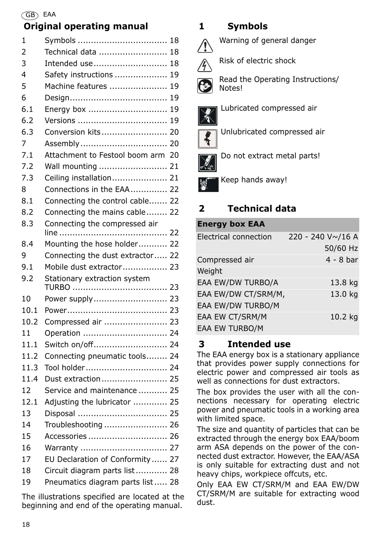
1 Symbols

Warning of general danger
Risk of electric shock

Read the Operating Instructions/ Notes!

Lubricated compressed air

Unlubricated compressed air

Do not extract metal parts!

Keep hands away!
2 Technical data
Energy box EAA
| Electrical connection | 220 - 240 V~/16 A |
| 50/60 Hz | |
| Compressed air | 4 - 8 bar |
| Weight | |
| EAA EW/DW TURBO/A | 13.8 kg |
| EAA EW/DW CT/SRM/M, | 13.0 kg |
| EAA EW/DW TURBO/M | |
| EAA EW CT/SRM/M | 10.2 kg |
| EAA EW TURBO/M |
3 Intended use
The EAA energy box is a stationary appliance that provides power supply connections for electric power and compressed air tools as well as connections for dust extractors.
The box provides the user with all the connections necessary for operating electric power and pneumatic tools in a working area with limited space.
The size and quantity of particles that can be extracted through the energy box EAA/boom arm ASA depends on the power of the connected dust extractor. However, the EAA/ASA is only suitable for extracting dust and not heavy chips, workpiece offcuts, etc.
Only EAA EW CT/SRM/M and EAA EW/DW CT/SRM/M are suitable for extracting wood dust.
Before extracting hazardous, combustible or explosive materials, make sure that the connected extraction system is suitable for these materials. Observe all applicable industrial safety regulations.
Festool accepts no liability for damage and accidents resulting from improper or incorrect use of the EAA or ASA, or subsequent modifications made by the user.
4 Safety instructions
Warning! Read all safety warnings and all instructions. Failure to follow the warnings and instructions may result in electric shock, fire and/or serious injury.
Save all warnings and instructions for future reference.
- The additional weight on the EAA/ASA (e.g. weight of electric or pneumatic tools, accessories) must not exceed 12 ~kg .
- Inspect the electric cables for damage at regular intervals. Have a qualified electrician or Festool after-sales service technician replace damaged cables with new cables.
- Ambient conditions: the room temperature must be between 0^ C and 50^ C. Air humidity must not exceed 80% .
5 Machine features
[1-1] Tool holder
[1-2] Aluminium pipe
[1-3] Permanent socket
[1-4] On/Off switch
[1-5] Socket AUTO 2
[1-6] Compressed air connection for pneumatic tools, adjusted via the pressure regulator on the maintenance unit
[1-7] Lock
[1-8] Extractor connector
[1-9] Socket AUTO 1
[1-10] Slide for opening and closing the extractor connector
[1-11] Unlubricated compressed air connection on EW version only*
- not on all versions included in the scope of delivery
6 Design
6.1 Energy box
The EAA energy box consists of two sections:
- Section containing electrical components such as sockets and selector switches for electric power tools (EW).
- Section containing pneumatic components, including connections for pneumatic tools (DW).
6.2 Versions
The different versions offer the following features:
EAA EW CT/SRM/M
- 3 sockets, 1 non-adjustable, unlubricated compressed air connection (not suitable for connecting Festool compressed air sanders!).
- Manually operated slide.
① The slides are linked mechanically. Dust can therefore only be extracted from one machine at any one time. The slide setting is monitored by a microswitch.
EAA EW TURBO/M
- 3 sockets, 1 non-adjustable, unlubricated compressed air connection (not suitable for connecting Festool compressed air sanders!).
- Manually operated slide.
Dust can be extracted from two machines at the same time. The slide setting is monitored by a microswitch (basic position: slide closed).
EAA EW/DW CT/SRM/M
- 3 sockets, 1 maintenance unit (pressure regulator, condensate trap, lubricator), 2 adjustable, lubricated compressed air connections, 1 non-adjustable, unlubricated compressed air connection (not suitable for connecting Festool compressed air sanders!).
- Manually operated slide.
(1) The slides are linked mechanically. Dust can therefore only be extracted from one machine at any one time. The slide setting is monitored by a microswitch.
EAA EW/DW TURBO/M
- 3 sockets, 1 maintenance unit (pressure regulator, condensate trap, lubricator), 2 adjustable, lubricated compressed air connections, 1 non-adjustable, unlubricated compressed air connection (not suitable
for connecting Festool compressed air sanders!).
- Manually operated slide.
Dust can be extracted from two machines at the same time. The slide setting is monitored by a microswitch (basic position: slide closed).
EAA EW/DW TURBO/A
- 3 sockets, 1 maintenance unit (pressure regulator, condensate trap, lubricator), 2 adjustable, lubricated compressed air connections, 1 non-adjustable, unlubricated compressed air connection (not suitable for connecting Festool compressed air sanders!).
- Pneumatically operated slides
Dust can be extracted from two machines at the same time. The slide setting is monitored by a microswitch (basic position: slide closed).
6.3 Conversion kits
The following conversion kits are available to convert the EAA to a different version at a later time:
CT/SRM/M >> TURBO/M
Modification: dust extracted by a stationary extraction turbine instead of a mobile dust extractor.
The connector [3-2] between the two mechanically operated slides [3-1] must be detached.
Modification: additional connection socket for pneumatic tools.
An additional maintenance unit (pressure regulator, condensate trap, lubricator) and a compressed air module including pneumatic hoses and connection to electronics via wiring harnesses must be mounted. Note: only trained and qualified electricians are authorised to perform this work!
EW/DW TURBO/M >> EW/DW TURBO/A (UBS EAA-MA: 495891)
Modification: pneumatically operated slides replace manual slides.
The complete floor group (the mechanically operated slides, vacuum connections and compressed air connections) must be replaced. In addition, solenoid valves must be fitted, the compressed air module adapted
and wiring harnesses for the electronics replaced. Note: only trained and qualified electricians are authorised to perform this work!
7 Assembly

WARNING
Risk of injury, damage to property
Before installing the unit, have a structural engineer check the static conditions of the planned attachment point!
Germany only: Festool offers you the opportunity to have the energy box or the boom arm assembled by an authorised fitter. The energy box or boom arm is assembled completely and handed over ready to use. We recommend using this service for quicker, more reliable assembly.
There are three different mounting options for the EAA:
1)Attachment to a boom arm (ASA CT/SRM 2500, ASA CT/SRM 5000, ASA TURBO 5000, ASA CT/SRM 6000, ASA TURBO 6000): the required assembly set is included with the boom arm.
2) Wall mounting: an additional assembly set is required (EAA-W: 495889).
3)Ceiling installation via bracket: an assembly set is required (EAA-D: 495899).
7.1 Attachment to Festool boom arm
(1) The energy box may only be used in combination with a Festool boom arm ASA with joint (see Fig. [4]). If you have an older boom arm with a previous model of joint, use conversion kit 489704.
The assembly set is included in the ASA scope of delivery and contains:
- Aluminium pipe for suspending the EAA
- Ready assembled mains cable and control line with international standard interface
- Compressed air line
- 2 x protective sleeves
- 3 x cable clips
- 2 x hose hooks
Procedure
- Mount the boom arm on a wall or pillar. Read the operating manual supplied with the boom arm.
The aluminium pipe is 1.6 ~m in length on delivery. The pipe can be shortened at the open end if necessary. We recommend adapting the length of the pipe so that the tool holder [1-1] on the EAA is positioned at forehead height. Always deburr the aluminium pipe after cutting to length!
Remove the rear panel of the EAA.
- Grease the bottom section of the aluminium pipe and slide into the Y-piece on the EAA [5-8] up to the stop.
- Tighten the two screws [5-9] on the gripper clamp to a tightening torque of 6Nm . The EAA is now seated securely on the aluminium pipe.
Skip to chapter 8 "Connections in the EAA".
7.2 Wall mounting
The assembly set contains:
- Cable set (mains power and control cable, 4 m long)
- Compressed air line (4 m long)
Aluminium pipe (50 mm in diameter, 350 mm long) for suspending the EAA - 2 × retaining plates, incl. screws and dowels
- Pipe/Suction hose adapter
- Mounting plate for maintenance unit
- Drain hose for condensate
Procedure
Remove the maintenance unit [2] from the rear panel of the EAA (not EW version).
Remove the rear panel of the EAA.
- Secure the mounting plate [6-4] to the top section of the EAA using the four screws [6-3].
- Attach the maintenance unit [6-1] to the mounting plate [6-4] using the screws [6-6].
Attach the enclosed air hose [7-1] with screw clamp [7-2] to the elbow piece with hose connector [7-3] on the maintenance unit.
Cut the blue fitted air hose (D16 mm) [8b-3] to a total length of 400 mm.
Turn the elbow piece [6-5] downwards and insert the shortened blue air hose.
Attach the condensate drain hose [5-11] to the connection point [6-2] on the maintenance unit.
Lay the hoses inside the EAA as shown in Fig. [5].
Insert the other end of the blue hose into the connector [5-1].
Grease the bottom section of the aluminium pipe and slide into the Y-piece on the EAA [5-8] up to the stop.
- Tighten the two screws [5-9] on the gripper clamp to a tightening torque of 6 Nm . The EAA is now seated securely on the aluminium pipe.
Connect all the hoses in the EAA (see chapter 8 "Connections in the EAA") before following the wall mounting instructions described below.
- Secure the rear panel to the EAA using the screws supplied.
Attach the lower retaining rail to the wall first (see Fig. [8a]). If the wall is made of concrete, use the enclosed dowels. Note: leave 1m of clearance between the panel and the ceiling.
Insert the EAA into the lower retaining rail from above. The hooks must engage in the EAA housing.
Attach the upper retaining rail [8b-1] to the EAA. The hooks must engage in the EAA housing. - Attach the upper retaining rail to the wall (see Fig. [8b]). If the wall is made of concrete, use the enclosed dowels.
- Attach the adapter [8b-2] to connect the suction hose to the aluminium pipe. Alternatively, you can extend the aluminium pipe by attaching a plastic pipe (install with antistatic discharge) or steel pipe for extraction systems, and then attach the adapter afterwards.
(1) This version does not allow the attachment of hose holders (see chapter 8.4).
7.3 Ceiling installation
The assembly set contains:
- Cable set (mains power and control cable, 2.5 m long)
- Compressed air line (2.5 m long)
- Aluminium pipe for suspending the EAA
- Hydraulic pipe
- 2 x clamps with rivet
- 2 x cable clips
- Bracket
Procedure
The aluminium pipe is 1.6 ~m in length on delivery. The pipe can be shortened at the open end if necessary. We recommend adapting the length of the pipe so that the tool holder [1-1] on the EAA is positioned at forehead height. Always deburr the aluminium pipe after cutting to length!
Remove the rear panel of the EAA.
Grease the bottom section of the aluminium pipe and slide into the Y-piece on the EAA [5-8] up to the stop.
- Tighten the two screws [5-9] on the gripper clamp to a tightening torque of 6Nm . The EAA is now seated securely on the aluminium pipe.
- Secure the bracket [9-2] to the ceiling via the four holes [9-1]. Use fasteners suitable for the relevant building material (e.g. tie rods, dowels).
Skip to chapter 8 "Connections in the EAA".
8 Connections in the EAA
8.1 Connecting the control cable
Wind the excess cable onto the holder [5-10].
- Place the flat seal supplied [10-1] over the cable connector [5-2] in the EAA.
Insert the contact box [10-2] into the cable connector [5-2] and tighten the screw [10-3].
- Secure the control cable under the strain relief on the EAA [5-3].
8.2 Connecting the mains cable
Wind the excess cable around the ridged section [5-6].
Place the flat seal supplied [10-6] over the contact box [5-7] in the EAA.
Insert the contact box [10-5] into the cable connector [5-7] and tighten the screw [10-4].
- Secure the mains cable under the strain relief on the EAA [5-4].
Plug the mains cable on the EAA into an earthed socket with a 16 A fuse.
Exception: If the connected dust extractor is from another manufacturer, a different configuration may be more appropriate - see chapter 9.1 "Mobile dust extractor".
(1) On country versions GB, CH and DK, the plug on the mains cable for the EAA/ASA must be removed and replaced with the accompanying rewirable plug. Note: only trained and qualified electricians are authorised to perform this work!
8.3 Connecting the compressed air line
① Applies only for ASA mounting and ceiling installation.
Cut the grey compressed air line to the correct length.
EW versions: Guide the air hose through the housing [11-1] onto the hose connector [11-3] and close the screw clamp[11-2].
EW/DW versions: Slide the grey air hose onto the hose connector at the maintenance unit inlet [7-3] and close the screw clamp [7-2].
- Secure the compressed air line and the mains power and control cable to the aluminium pipe [12-2]using the three gripper clamp supplied [12-1].
Insert the end of the blue hose into the connection[5-1] and guide the hose through the opening on the housing.
Once you have attached all the connections inside the EAA, mount the rear panel on the EAA.
Push the blue air hose onto the elbow piece [2-5] on the maintenance unit.
8.4 Mounting the hose holder
The hose holder is used to store consumable materials and hoses. Attach the two hose holders to the rear panel of the EAA (see Fig. [13]).
- Secure the hose holder [13-4] by screwing an Allen screw [13-2] with washer [13-3] into both holes using the Allen key [13-1] supplied.
- Secure the rear panel to the EAA using the screws supplied.
9 Connecting the dust extractor
A mobile dust extractor or the stationary TURBO extraction system can be used to extract dust.
9.1 Mobile dust extractor
CT mobile dust extractors, series CT 22, CT 33, CT 44, CT 55
Fit the assembly set (module EAA CT22/ 33/44/55: 495756) for the control cable to the CT mobile dust extractor (see assembly instructions).
CT mobile dust extractor series CT 26, CT 36
Fit the assembly set (module EAA CT26/ 36:494896) to the CT mobile dust extractor (already fitted on CTM 36 LE and CTL 36 LE models).
Plug the control cable into the socket on the extractor.
SRM mobile extractor and other brands of extractor
Connecting the control cable is no longer possible. If the dust extractor has an appliance socket with automatic switch-on unit, the mains cable on the EAA must be plugged into this appliance socket so that the automatic switch-on unit on the dust extractor functions. However, note the maximum capacity of the appliance socket. Not all EAA functions can be used. We therefore recommend using a Festool mobile dust extractor.
Plug the extractor hose into the extractor opening on the dust extractor.
(1) We recommend using rotating adapter D50 DAS-AS to connect the extractor hose to the dust extractor.
If the EAA is quite far away from the mobile dust extractor, part of the extractor hose should be replaced by a plastic pipe or a steel pipe designed for extraction systems (diameter 50~mm ). This reduces the air flow resistance in the extraction line and improves the suction power at the EAA.
9.2 Stationary extraction system TURBO
Plug the control cable into the socket on the extraction system.
Plug the extractor hose into the extractor opening on the extraction system (D75).
10 Power supply
Power and compressed air is supplied through the energy box.
10.1 Power
All EAA versions have three sockets. Socket [1-3] is connected permanently to the power. The two sockets AUTO 1 [1-9] and AUTO 2 [1-5] are live when the selector switch [1-4] is set to the "AUTO" position. If the switch is set to "0" or "MAN", the sockets are disconnected from the power supply.

CAUTION
Risk of accident, electric shock
If tools are operated from all three sockets simultaneously, the maximum power available at each socket is 1200W.
If the mains cable on the EAA is plugged into the appliance socket on a dust extractor (see chapter 9.1), always observe the maximum capacity of the appliance socket on the dust extractor. The total power supplied via the output cables on the three EAA sockets must not exceed the maximum capacity of the appliance socket on the dust extractor.
10.2 Compressed air
The EW versions have a non-adjustable connection for unlubricated compressed air [1-11].

CAUTION
Risk of accident, electric shock
The compressed air from this connection cannot be adjusted, the pressure from the in-house compressed-air system is supplied to this connection. Festool compressed air sanders should not be attached via this connection.
EW/DW versions have a maintenance unit (see Fig.[2]), consisting of a pressure regulator[2-1], manual condensate trap [2-8] and lubricator [2-6], two adjustable connections for lubricated compressed air [1-6] and a non-adjustable connection for unlubricated compressed air [2-7]. The flow pressure preset at the pressure regulator is supplied to all three connections. The two connections for lubricated compressed air are for attaching pneumatic tools.
The following is required for correct operation:
- Compressed air: 6 bar flow pressure
- Min. suction capacity: 400 l/min for each connected Festool compressed air sander.

WARNING
Risk of injury
The air pressure at the energy box should not exceed 8 bar.
The maximum permitted flow pressure for Festool compressed air sanders is 6.5 bar.
Set the pressure regulator [2-1] to a flow pressure of 6 bar before operating a pneumatic tool.
Note: The pneumatic slide control on the EW/DW Turbo/A version will not function properly if the pressure is too low (under 4 bar).
11 Operation

WARNING
Risk of accidents
When the system is assembled in full, a protective conductor test must be conducted by a qualified electrician in accordance with EN 60204-1 before the system is operated. The test current must be 10A at 50Hz . The test must be performed between the PE terminal and all main points on the protective conductor system.
11.1 Switch on/off
The selector switch on the mobile dust extractor or stationary TURBO extraction system must be set to the "AUTO" position so that dust extraction system is activated only when an electric or pneumatic tool is operating.
If the dust extraction system does not have an "AUTO" position, the system must be switched on manually before work begins. In this case, the EAA automatic function described below is not available.
The switch [1-4] serves as an On/Off switch. It has three positions:
- Position "0": the EAA is switched off, all sockets are without power.
- Position "AUTO": All sockets are live. Dust extraction starts when an electric or
pneumatic tool [1-5], [1-9] connected to one of the sockets is switched on.
- Position "MAN": All sockets are live. Dust extraction starts immediately. An additional feature of the EW/DW Turbo/A version: the right slide stays open while the other slide remains closed.

CAUTION
Risk of injury from tools starting up unexpectedly
Before setting the switch to the "AUTO" or "MAN" position, make sure that the connected tool is switched off.
11.2 Connecting pneumatic tools
The EW/DW version of the EAA is designed for connecting up to two compressed air sanders to the Festool IAS system.
Insert the end of the compressed air line into the quick-coupling socket [1-6].
- Open the catch for the extractor opening by pulling out the locking pin [1-7] and rotating 90^ .
Insert the connecting sleeve on the IAS adapter into the extractor connector [1- 8].
① Note: only new connecting sleeves have a slot for engaging the locking pin.
Align the IAS adapter so that the connecting hoses do not kink.
- Only applies for wall mounting: condensate from the condensate drain hose must not contaminate the IAS hose.
Turn the locking pin [1-7] back 90^ and release to engage. The IAS adapter is now locked.
Festool CT/SRM dust extractors only: connect the coupling connector on the extractor with the quick-coupling socket [1-6].
11.3 Tool holder
The tool holder[1-1]is used to hang up electric and pneumatic tools.

CAUTION
Risk of accidents
The additional weight on the EAA (e.g. weight of electric or pneumatic tools, accessories) may not exceed 12kg .
11.4 Dust extraction

WARNING
Dust hazard
Dust can be hazardous to health. Always work with a dust extractor.
Always read applicable national regulations before extracting hazardous dust.
If national safety regulations stipulate that dust extractors must have a suction power monitoring function (volumetric flow monitoring), only one extractor opening [1-8] on the EAA can be opened.
Version CT/SRM/M
The slide [1- 10] ensures that only one extractor opening is open and the other one is closed so that the dust extraction system only operates with one machine. You can decide which extraction opening to use by changing the position of the slide.
Version TURBO/M
When extracting non hazardous dust, the TURBO/M version can operate and extract from two machines at the same time.
Version TURBO/A
The EAA detects which tool is operating and opens the corresponding extractor opening automatically. The simultaneous operation and extraction of two machines is also possible.
(1) Only the right extractor connector is operational when the rotary switch [1-4] is set to "MAN".
12 Service and maintenance

WARNING
Risk of accidents
Disconnect the EAA/ASA from the power and compressed air supply before performing any maintenance and repair work.
All maintenance and repair work on the electrical or electronic system must always be carried out by a qualified electrician.
12.1 Adjusting the lubricator
- Set the pressure regulator [2-1] to a flow pressure of 0 bar. Note: the entire service unit must be depressurised!
Unscrew the oil vessel [2-6].
Fill the oil vessel 3/4 full with special oil (481722).
Screw the oil vessel back on. - Set the pressure regulator to a flow pressure of 6 bar before operating a pneumatic tool.
Make sure that the vent screw [2-2] is closed.
Screw the adjusting screw [2-4] in the viewing window all the way in.
Then unscrew the adjusting screw approx. 1/4 of a turn.
Observe the oil drops in the viewing window [2-3] while the pneumatic tool is operating.
Set the adjusting screw so that one drop of oil escapes every 10-20 minutes.
Screw the condensate screw [2-8] all the way in.
13 Disposal
Do not throw the tool in your household waste!! Dispose of machines, accessories and packaging at an environmentally responsible recycling centre. Observe the valid national regulations.
EU only: European Directive 2002/96/EC stipulates that used electric tools must be collected separately and disposed of at an environmentally responsible recycling centre.
14 Troubleshooting
| Electrical faults | Action | Service |
| No power at perma-nent socket | Check the mains cable connection on the EAA | |
| Check the mains cable connection at the mains socket | ||
| No fault identified | Request asis-tance | |
| No power at automatic socket | Check the mains cable connection on the EAA | |
| Check the mains cable connection at the mains socket | ||
| No fault identified | Request asis-tance | |
| Slide does not open when electric power tool is plugged in | Check the control cable at both ends | |
| Open the rear panel and check the solenoid/con-trol cable and reed contact | ||
| Check the compressed air connection | ||
| No fault identified | Request asis-tance | |
| Slide does not close when electric power tool is plugged in | Check the control cable at both ends | |
| Open the rear panel and check the solenoid/con-trol cable and reed contact | ||
| Check the compressed air connection | ||
| No fault identified | Request asis-tance | |
| Selector switch set to manual: extractor does not start | Check whether the control cable is connected at both ends | |
| Check whether the extractor/turbine mains cable is connected | ||
| No fault identified | Request asis-tance | |
| Extractor / turbine operating but slide does not open | Check whether the control cable is connected at both ends | |
| Check the flow pressure, min. 4 bar | ||
| No fault identified | Request asis-tance | |
| Electric power tool does not start | Check whether the selector switch is set to Auto | |
| Check whether the mains cable is connected | ||
| Check whether the electric power tool is faulty | ||
| No fault identified | Request asis-tance |
15 Accessories
Use only original Festool accessories and Festool consumable material intended for this machine because these components are designed specifically for the machine. Using accessories and consumable material from other suppliers will most likely affect the
quality of your working results and limit any warranty claims. Machine wear or your own personal workload may increase depending on the application. Protect yourself and your machine, and preserve your warranty claims by always using original Festool accessories and Festool consumable material!
The order numbers of the accessories and tools can be found in the Festool catalogue or on the Internet under "www.festool.com".
16 Warranty
We offer a warranty for material and production defects for all our tools in accordance with the locally applicable legal provisions, but for a minimum of 12 months. Within the EU member states, the warranty period is 24 months (verification through invoice or delivery note). Damage caused by the operator, natural wear, overloading, incorrect handling or through the use of the equipment not specified in the operating manual, or damage which was known at the time of purchase, is not covered by the warranty. Furthermore, damage caused by the use of non-original accessories and consumable materials (e.g. sanding pads) is also excluded.
Complaints can only be accepted if the tool is returned while still assembled to the supplier or an authorised Festool Customer Service workshop. Keep the operating manual, safety instructions, spare parts list and purchase receipt in a safe place. Otherwise the current warranty conditions of the manufacturer shall apply.
Note
Due to continuous research and development work, we reserve the right to make changes to the technical content of this documentation.
17 EU Declaration of Conformity
| Energy box | Serial no. |
| EAA EW CT/SRM/M | 495910, 495912 |
| EAA EW TURBO/M | 495900, 495902 |
| EAA EW/DW CT/SRM/M | 495911, 495913, 495915, 495916, 495917, 495918, 495919 |
| EAA EW/DW TURBO/M | 495901, 495903, 495905, 495906, 495907, 495908, 495909 |
| EAA EW/DW TURBO/A | 495760, 495893, 495895, 495896, 495897, 495898, 495899 |
| Year of CE mark: 2008 | |
| We declare under sole responsibility that this product complies with the following directives and standards: | |
| 98/37/EC (until 28 Dec. 2009), 2006/42/EC (after 29 Dec. 2009), 2006/95/EC, 2004/108/EC, EN 60204-1, EN 55014-1, EN 55014-2, EN 60529, EN 294 | |
Festool GmbH
Wertstr. 20, D-73240 Wendlingen, Germany
p9a. 7. Jcb anan 8inw
Head of Research, Development and Technical Documentation
10.2008
18 Circuit diagram parts list
The circuit diagram appears at the end of this operating manual.
| Name | Quan-tity | Pt no. | Designation, type | Design |
| A1 | 1 | 476 160 | Electronics EAA Festool | L x W: 85 mm x 78 mm |
| S1 | 1 | 452 050 | Mains switch AUTO/0/MAN Bernhard & Schulte type 3032 / 20A | 4x change over switch with off-position |
| X1 | 1 | 475 168 | Appliance connector GSA U2000NLO Hirschmann order no. 933 378-100 | 2-pole + PE |
| X2 | 1 | 452 099 | Connecting terminal KL24/3 Wieland order no. 99.900.8210.0 | 3-pole L/N/PE |
| X3, X4, X5 | 3 | Built-in power socket Depends on country | 2-pole + PE | |
| X6 | 1 | 475 170 | Appliance connector GSSNA 200 Hirschmann order no. 933 110-100 | 2-pole + PE |
| X7, X9 | 2 | stud bolt | M4 x 22 mm | |
| X8 | 1 | stud bolt | M4 x 12 mm | |
| Y1, Y21 | 2 | Coil of electromagnetic value 1V1 and 2V1 Part no. 475154 Festo CPE10-M1BH-5L-M7 | ||
| 1S1, 2S1 | 2 | 475 535 | Microswitch Omron D2VW-01L3-1 SPST-NO | 1x selector switch |
| 1S2, 2S22 | 2 | 476 460 | Reed contact Meder MK3-1A66 | 1x NOC |
- Only for EAA EW/DW TURBO/A
- Only for EAA EW/DW TURBO/A, EAA EW/DW TURBO/M and EAA EW/DW CT/SRM/M
19 Pneumatics diagram parts list
The pneumatics diagram appears at the end of this operating manual (applies for EW/DW versions only):
| Name | Version | Quan-tity | Pt. no. | Designation,type | Notes,supplier |
| 0V1 | EW/DW TURBO/A | 1 | 495435 | Compressed air module EW/DW TURBO | Festool |
| EW/DW TURBO/M; EW/DW CT/SRM/M | 1 | 495808 | |||
| 0Z1 | All | 1 | 495434 | Combination of main-tenance devices FRD-1/2-D-MIDI | Festo no.: 159584/159592/192576 Festool |
| 0Z2 | All | 1 | E036905 | Quick safety couplingSSK-NW7.8-G1/4a | Unlubricated outputCejn |
| 0Z3 | All | 1 | 475165 | Safety couplingERG 071 152 | Lubricated outputPrevost |
| 0Z4 | All | 1 | 475165 | Safety couplingERG 071 153 | Lubricated outputPrevost |
| 1A1,2A1 | EW/DW TURBO/A | 2 | 475153 | Double action cylinderADN-20-60-I-P-A | FESTO no.:536 365FESTO |
| 1S1,2S1 | EW/DW TURBO/A | 2 | 475535 | Microswitch, NOCD2VW-01L3-3HS(CHN) | Omron |
| 2S2 | All | 1 | 452117 | Reed contactMK3-1A71-BV 588 | Pneumatic tool 2Meder |
| 1V1,2V2 | EW/DW TURBO/A | 2 | 475154 | Monostable 5/2-wayvalveCPE10-M1BH-5L-M7 | FESTO no.:196 927FESTO |
| 1S2 | All | 1 | 452117 | Reed contactMK3-1A71-BV 588 | Pneumatic tool 1Meder |
El的时间里 y la calidad de partículas queSEOSEOSEOSEOSEOSEOSEOSEOSEOSEOSEOSEOSEOSEOSEOSEOSEOSEOSEOSEOSEOSEOSEOSEOSEOSEOSEOSEOSEOSEOSEOSEOSEOSEOSEOSEOSEOSEOSEOSEOSEOSEOSEOSEOSEOSEOSEOSEOSEOSEOSEOSEOSEOSEOSEOSEOSEOSEOSEOSEOSEOSEOSEOSEOSEOSEOSEOSEOSEOSEOSEOSEOSEOSEOSEOSEOSEOSEOSEOSEOSEOSEOSEOSEOSEOSEOSEOSEOSEOSEOSEOSEOSEOSEOSEOSEOSEOSEOSEOSEO SEO
E EAA
Varning for allman risk!
Varning for elstötar
CHIMTE NHEBMo6JOK [2] Ha 3aHnei CTeHKe EAA (3TO He OTHOCHTcK MoJeIN EW).
ДемоHTиPyITe 3aHIOU cTeHky EAA.
ПрииВиHTиTe KpeпeжнHyо ПлactиHy [6-4] C ПOMоцьЮ YeТырEx BИNTOB [6-3] На ВерхнeйЧаTs EAA.
YCTaHOBNTe PHeBMo6Iok [6-1] Ha KpeJexKHOI pIacTInHe [6-4] C NOMOuBIO BnHTOB [6-6].
3aKpeNITe npilaraembI nHeBMOJlaHr [7-1]c NOMOuB BnHTOBOTo XOMyTa [7-2] Ha nHEBMaTnueCKOM yroJIbHNKe c HAKOHeuHKnOM ⅢLaHra [7-3] nHeBMo6JIOka.
YKOPOTHTe yCTaHOBJeHHbI CHNHn PHeBMOUHaHr (D16 MM) [8b-3] Ha 200 MM dJa DoCTNXKeHnO6uEe DInHbI 400 MM.
ПовернITE ПHEBMaTnueckn yroIbHNK [6-5] BHN3 N BCTaBbTe yKOpOeHHbI CNHIN PHeBMoUJHaHr B yroJIbHNK.
BCTaBbTe ⅢaHrДЯ OTbOJa KOHdEHCata [5-11]В NOДСоЕДИНHTeJIbHbI YXOMyT [6-2]ПневMo6лoka.
ПроложиTeшлангиВнутprEAA,кak n3o6paженHa рис. [5].
Дуров Конец снего Шанга Вставытев подсоединенье[5-1].
HaHeCnTe CMa3Ku Ha HIXHIOU qAcTb aIIOHMnHnEBoi Tpy6bl, N BCTaBbTe ee Do ynpora BV-06pa3HbI nepexoDnK EAA [5- 8].
3aTaNHe 3axmHyIO cKo6y C NOMOzbu O DByX BnHTOB [5-9] MOMeHTOM 3aTJxKn 6 H·M. TeNepb EAA npouHo yCTaHOBJIen Ha aIOMHNHeBOr Tpy6e.
- Original operating manual
- Symbols
- Technical data
- Intended use
- Safety instructions
- Save all warnings and instructions for future reference.
- Machine features
- Design
- Energy box
- Versions
- EAA EW CT/SRM/M
- EAA EW TURBO/M
- EAA EW/DW CT/SRM/M
- EAA EW/DW TURBO/M
- EAA EW/DW TURBO/A
- Conversion kits
- CT/SRM/M >> TURBO/M
- EW/DW TURBO/M >> EW/DW TURBO/A (UBS EAA-MA: 495891)
- Assembly
- WARNING
- Risk of injury, damage to property
- There are three different mounting options for the EAA:
- Attachment to Festool boom arm
- Procedure
- Wall mounting
- Ceiling installation
- Connections in the EAA
- Connecting the control cable
- Connecting the mains cable
- Connecting the compressed air line
- Mounting the hose holder
- Connecting the dust extractor
- Mobile dust extractor
- CT mobile dust extractors, series CT 22, CT 33, CT 44, CT 55
- CT mobile dust extractor series CT 26, CT 36
- SRM mobile extractor and other brands of extractor
- Stationary extraction system TURBO
- Power supply
- Power
- CAUTION
- Risk of accident, electric shock
- Compressed air
- Risk of injury
- Operation
- Risk of accidents
- Switch on/off
- Risk of injury from tools starting up unexpectedly
- Connecting pneumatic tools
- Tool holder
- Dust extraction
- Dust hazard
- Version CT/SRM/M
- Version TURBO/M
- Version TURBO/A
- Service and maintenance
- Adjusting the lubricator
- Disposal
- Troubleshooting
- Accessories
- Warranty
- Note
- EU Declaration of Conformity
- Festool GmbH
- Circuit diagram parts list
- Pneumatics diagram parts list
- E EAA
Brand : FESTOOL
Model : EAA
Category : Welding machine