USER MANUAL HT 40 AKG
wireless microphone system
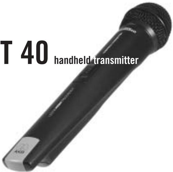
111 40 handheld transmitter
Bedienungshinweise S.2
Bitte vor Inbetriebnahme des Gerätes essen!
User Instructions. p. 11
Please read the manual before using the equipment!
Mode d'emploi . p. 20
Veuillez ire cette notice avant d'utiliser le système!
Istruzioni per l'uso . p. 29
Prima diutilizzare l'apparecchio,leggere il manuale!
Modo de empleo . p. 38
Antes de utiliser el equipo, sirvase leer el manual!
Instruções de uso p. 47
Favor leia este manual antes de usar o equipamento!

This equipment has been tested and found to comply with the limits for a Class B digital device, pursuant to Parts 74, 15, and 90 of the FCC Rules. These limits are designed to provide reasonable protection against harmful interference in a residential installation. This equipment generates, uses, and can radiate radio frequency energy and, if not installed and used in accordance with the instructions, may cause harmful interference to radio communications. However, there is no guarantee that interference will not occur in a particular installation. If this equipment does cause harmful interference to radio or television reception, which can be determined by turning the equipment off and on, the user is encouraged to try to correct the interference by one or more of the following measures:
Shielded cables and I/O cords must be used for this equipment to comply with the relevant FCC regulations.
Changes or modifications not expressly approved in writing by AKG Acoustics may void the user's authority to operate this equipment.
This device complies with Part 15 of the FCC Rules. Operation is subject to the following two conditions: (1) this device may not cause harmful interference, and (2) this device must accept any interference received, including interference that may cause undesired operation.

1 Safety and Environment
1.1 Safety
- Do not expose the equipment to direct sunlight, excessive dust, moisture, rain, mechanical vibrations, or shock.
1.2 Environment
- Be sure to dispose of used batteries as required by local waste disposal rules. Never throw batteries into a fire (risk of explosion) or garbage bin.
- When scrapping the equipment, remove the batteries, separate the case, circuit boards, and cables, and dispose of all components in accordance with local waste disposal rules.

2 Description
2.1 Introduction
Dear Customer:
Thank you for purchasing an AKG product. This Manual contains important instructions for setting up and operating your equipment. Please take a few minutes to read the instructions below carefully before operating the equipment. Please keep the Manual for future reference. Have fun and impress your audience!
2.2 Unpacking
| | |
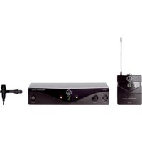
| 1 HT 40 Handheld Transmitter | 2 AA size 1.5 V dry batteries | 1 SA 43 stand adapter, black color code clip |
Check that the package contains all the parts listed above. If anything is missing, please contact your AKG dealer.
2.3 Optional Accessories
W 880 foam windscreen
2.4 Description
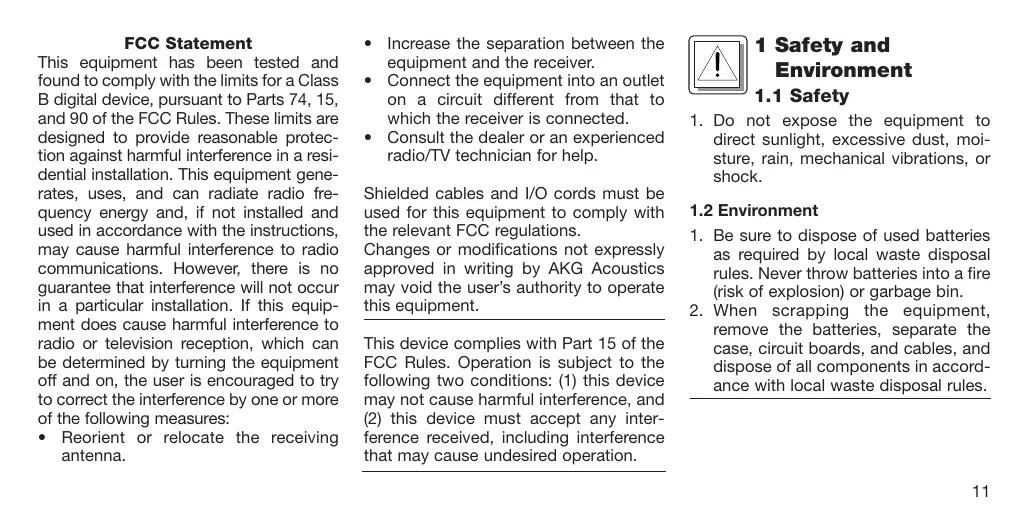
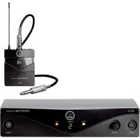
The HT 40 handheld transmitter operates on one fixed, quartz stabilized frequency in the 710 MHz to 865 MHz UHF carrier frequency range and uses an antenna integrated in the body.
The microphone element permanently mounted on the transmitter is acoustically identical to the D 880 vocal microphone from AKG. This microphone features a built-in wind and pop filter to reduce wind and breath noise and provides low handling noise sensitivity, high gain before feedback, and brilliant sound quality.
2.5 Controls (See fig. 1 on page 13)
1 On/Off switch: This slide switch provides three positions indicated in the display window:
ON: Power to the transmitter is on. MUTE: The signal delivered by the microphone element is muted while power and the RF carrier frequency remain on. This prevents the receiver from responding to interference from other transmitters.
OFF: Power to the transmitter is off.
2 Status LED: Indicates battery status. LED flashes momentarily upon switching ON and extinguishes: batteries are OK.
LED lights constantly: batteries will be dead in about 50 minutes.
3 Color Code: The color of this plastic clip indicates the carrier frequency of your transmitter. Receivers tuned to the same frequency are marked with
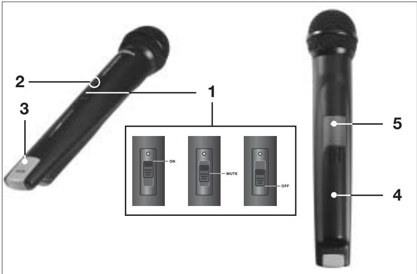
Fig. 1: HT 40 controls.
the same color (refer to section 2.6). You can remove the color code clip on the HT 40 and replace it with the supplied black clip.
4 Battery Compartment Lid: Refer to section 3.2.
5 Carrier Frequency Label: The label above the battery compartment indicates the carrier frequency and approval marks of your transmitter.
2.6 Color Code Table
| Frequency | Color |
| US54: | 710.400 MHz | reddish brown |
| US58: | 734.600 MHz | purple |
| KR3: | 745.650 MHz | mint green |
| KR4: | 750.900 MHz | dark gray |
| EU62: | 802.525 MHz | Bordeaux red |
| EU63: | 812.800 MHz | yellow |
| UK69A: | 854.900 MHz | violet |
| UK69B: | 858.200 MHz | green |
| ISM1: | 863.100 MHz | melon yellow |
| ISM2: | 864.375 MHz | gray |

3 Setting Up
Important: Prior to setting up your WMS 40, check that the transmitter and receiver are tuned to the same frequency. The easiest way to do this is to compare the color codes on the transmitter and receiver.
3.1 Placing the Receiver
Reflections off metal parts, walls, ceilings, etc. or the shadow effects of musicians and other people may weaken or cancel the direct transmitter signal. For best results, place the receiver as follows:
- Place the receiver near the performance area (stage). Make sure, though, that the transmitter will never get any
closer to the receiver than 10 ft (3 m). Optimum separation is 16 ft. (5 m).
- Check that you can see the receiver from where you will be using the transmitter.
- Place the receiver at least 5 ft. (1.5 m) away from any big metal objects, walls, scaffolding, ceilings, etc.
3.2 Inserting and Testing Batteries
Refer to fig. 2)
- Depress the snap hook on the battery compartment lid (4).
- Pull the battery compartment lid (4) down to remove it from the transmitter.
Important: The foam pads on the inside of the battery compartment lid holds the batteries in place. Do not remove the foam pad. If you do, the batteries will not be held in place properly and may cause a rattling noise.
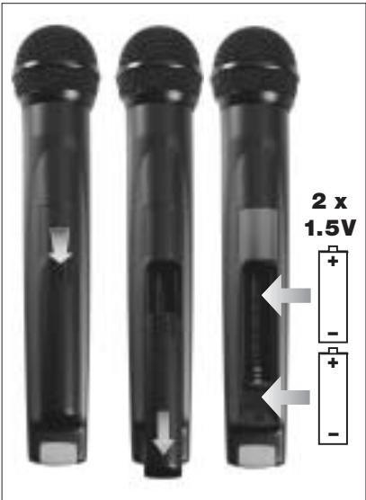
Fig. 2: Inserting the batteries.
- Insert the supplied batteries into the battery compartment conforming to the polarity marks.
The transmitter will not function with incorrectly inserted batteries.
- Set the on/off switch (1) to "ON" to switch the power to the transmitter on. The status LED (2) will flash momentarily. If the batteries are in good condition, the status LED (2) will extinguish.
If the status LED (2) illuminates the batteries will be dead within about 50 minutes. Replace the batteries with new ones as soon as possible.
If the status LED (2) fails to flash momentarily the batteries are dead. Insert new batteries.
- To close the battery compartment, slide the battery compartment lid (4) onto the battery compartment from below to the point that it will click shut.
3.3 Setting Up the Transmitter
- Switch power to the receiver on and check the setting of the VOLUME control:
Fully CCW if you connected the receiver to a microphone input.
Fully CW if you connected the receiver to a line input.
-
Set the on/off switch (1) to "ON" to switch power to the transmitter on. Since the HT 40 handheld transmitter has been designed specifically for the integrated microphone element, there is no need to set gain on the handheld transmitter. Therefore, the handheld transmitter has no level or gain control.
-
Switch power to your sound system or amplifier on.
-
Talk or sing into the microphone and set the levels on your mixer or amplifier referring to the appropriate instruction manual or by ear.
3.4 Replacing the Color Code Clip
(Refer to fig. 3)
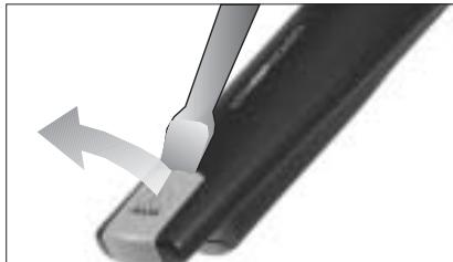
Fig 3: Replacing the color code clip.
- Use a screwdriver to lift the upper end of the color code clip.
- Pull the color code clip off the transmitter case.
- Slide the supplied black clip onto the transmitter to the point that it snaps into place with an audible click.
3.5 Before the Soundcheck
-
Move the transmitter around the area where you will use the system to check the area for "dead spots", i.e., places where the field strength seems to drop and reception deteriorates. If you find any dead spots, try to eliminate them by repositioning the receiver. If this does not help, avoid the dead spots.
-
The RF LED on the receiver going out means no signal is being received or the squelch is active.
Switch power to the transmitter ON and/or move closer to the receiver, to the point that the RF LED on the receiver will come back on.

4 Microphone Technique
A handheld vocal microphone provides many ways of shaping
the sound of your voice as it is heard over the sound system.
The following sections contain useful hints on how to use your HT 40 handheld transmitter for best results.
4.1 Working Distance and Proximity Effect
Basically, your voice will sound the bigger and mellower, the closer you hold the microphone to your lips. Moving away from the microphone will produce a more reverberant, more distant sound as the microphone will pick more of the room's reverberation.
You can use this effect to make your voice sound aggressive, neutral, insinuating, etc. simply by changing your working distance.
Proximity effect is a more or less dramatic boost of low frequencies that occurs when you sing into the microphone from less than 2 inches. It gives
more "body" to your voice and an intimate, bass-heavy sound.
4.2 Angle of Incidence (See fig. 4)

Fig. 4: Angle of incidence
Sing to one side of the microphone or above and across the microphone's top.
This provides a well-balanced, natural sound.
If you sing directly into the microphone, it will not only pick up excessive breath noise but also overemphasize "sss", "sh", "tch", "p", and "t" sounds.
4.3 Feedback (Refer to fig. 5)
Feedback is the result of part of the sound projected by a speaker being picked up by a microphone, fed to the amplifier, and projected again by the speaker. Above a specific volume or "system gain" setting called the feedback threshold, the signal starts being regenerated indefinitely, making the sound system howl and the sound engineer desperately dive for the master fader to reduce the volume and stop the howling.
To increase usable gain before feedback, the microphone element of the HT 40 handheld transmitter has a supercardioid polar pattern. This means that the microphone is most sensitive to
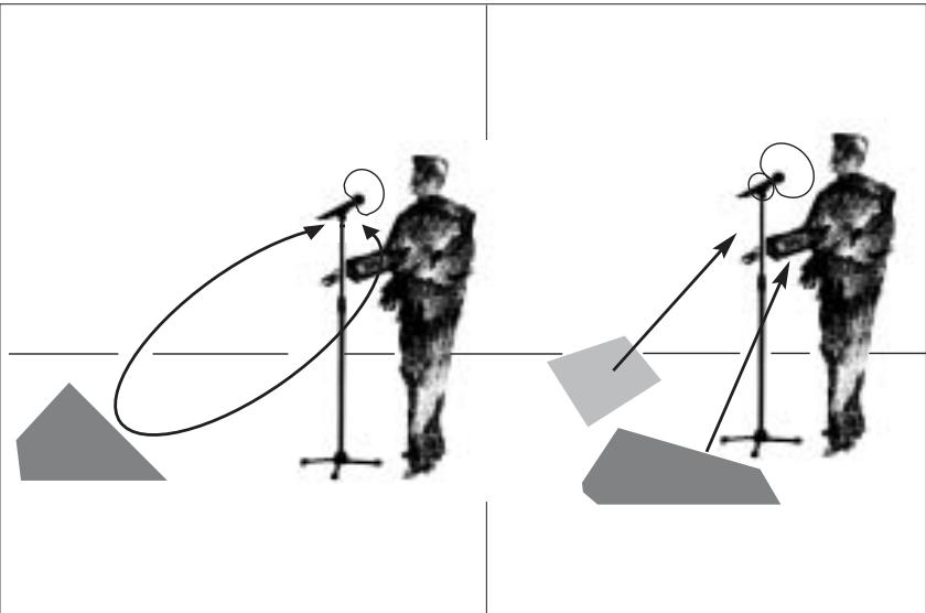
Fig. 5: Feedback
sounds arriving from in front of it (your voice) while picking up much less of sounds arriving from the sides or rear (from monitor speakers for instance).main ("FOH") speakers in front of the microphones (along the front edge of the stage). If you use monitor speakers, be sure never to point any microphone directly at the monitors, or at the FOH speakers.
Feedback may also be triggered by resonances depending on the acoustics of the room or hall. With resonances at low frequencies, proximity effect may cause feedback. In this case, it is often enough to move away from the microphone a little to stop the feedback.
4.4 Backing Vocals (Refer to fig. 6)
- Never let more than two persons share a microphone.
- Ask your backing vocalists never to sing more than 35 degrees off the

Fig. 6: Backing vocals.
microphone axis.
The microphone is very insensitive to off-axis sounds. If the two vocalists were to sing into the microphone from a wider angle than 35 degrees, you may end up bringing up the fader of
the microphone channel far enough to create a feedback problem.
4.5 Troubleshooting
For troubleshooting hints, refer to the instruction manual of your receiver.

5 Cleaning
5.1 Surfaces
To clean the transmitter case, use a soft cloth moistened with water.
5.2 Internal Windscreen
- Unscrew the wire-mesh cap of the handheld transmitter CCW and remove the wire-mesh cap from the transmitter.
- Remove the windscreen (foam sheet) from the wire-mesh cap.
-
Wash the windscreen in mild soap suds.
-
As soon as the windscreen has dried, replace it in the wire-mesh cap and screw the wire-mesh cap onto the transmitter CW.

6 Specifications
Carrier frequency range 710 to 865 MHz
Modulation FM
Audio bandwidth 40 to 20,000 Hz
Frequency stability (-10^ to +50^) ±15 kHz
Rated deviation 15 kHz
T.H.D. at 1 kHz typ. 0.8%
Compander integrated
Signal/noise ratio 103 dB(A) typ.
RF output 10 mW typ.
Current consumption 70 mA typ.
Power requirement 2 x 1.5-V AA size batteries
Battery life 30 hours typ.
Audio input level for rated deviation 100 mV/1 kHz
Input impedance 220 kΩ
Size length: 258 mm (10 in.);
dia.: 40 mm (1.6 in.)
Net weight 245 g (8.7 oz.)
This product complies with the following standards:
Las reflexiones de la seals transmitora en piezas metálicas, murallas, techos, etc. o el eclipsado por cuerpos humanosSEOSEOSEOSEOSEOSEOSEOSEOSEOSEOSEOSEOSEOSEOSEOSEOSEOSEOSEOSEOSEOSEOSEOSEOSEOSEOSEOSEOSEOSEOSEOSEOSEOSEOSEOSEOSEOSEOSEOSEOSEOSEOSEOSEOSEOSEOSEOSEOSEOSEOSEOSEOSEOSEOSEOSEOSEOSEOSEOSEOSEOSEOSEOSEOSEOSEOSEOSEOSEOSEOSEOSEOSEOSEOSEOSEOSEOSEOSEOSEOSEOSEOSEOSEOSEOSEOSEOSEOSEOSEOSEOSEOSEOSEOSEOSEOSEOSEOSEOSEO SEOEO SEOEO SEOEO SEOEO SEOEO SEOEO SEOEO SEOEO SEOEO SEOEO SEOEO SEOEO SEOEO SEOEO SEOEO SEOEO SEOEO SEOEO SEOEO SEOEO SEOEO SEOEO SEOEO SEOEO SEOEO SEOEO SEOEO SEOEO SEOEO SEOEO SEOEO SEOEO SEOEO SEOEO SEOEO SEOEO SEOEO SEOEO SEOEO SEOEO SEOEO SEOEO SEOEO SEOEO SEOEO SEOEO SEOEO SEOEO SEOEO SEOEO SEOEQ

Fig. 2: Colocar as pilhas
4.5 Resolver problemas
Os avisos para resolver problemas encontrará no manual do usuario de seu receptor.

5 Limpeza
5.1 Superficies
| R&TTEd Countries | |
| Set | MHz | AT | BE | CH | DE | DK | ES | FR | GB | GR | IE | IS | IT | LI | LU | NO | NL | PT | SE | FI |
| US54 | 710.4 | ✓ | ✓ | ✓ | ✓ | - | - | ✓ | - | - | ✓ | ✓ | ✓ | ✓ | ✓ | - | ✓ | ✓ | ✓ | - |
| US58 | 734.6 | ✓ | ✓ | ✓ | ✓ | - | - | ✓ | - | - | ✓ | ✓ | ✓ | ✓ | ✓ | - | ✓ | ✓ | ✓ | - |
| KR3 | 745.650 | - | - | ✓ | - | - | - | ✓ | - | - | - | - | - | ✓ | ✓ | - | ✓ | ✓ | ✓ | - |
| KR4 | 750.900 | - | - | ✓ | - | - | - | ✓ | - | - | - | - | - | ✓ | ✓ | - | ✓ | ✓ | ✓ | - |
| EU62 | 802.525 | - | - | ✓ | ✓ | ✓ | - | ✓ | - | - | ✓ | ✓ | ✓ | ✓ | ✓ | ✓ | - | ✓ | ✓ | ✓ |
| EU63 | 812.8 | - | - | ✓ | ✓ | ✓ | - | ✓ | - | - | ✓ | ✓ | ✓ | ✓ | ✓ | ✓ | ✓ | ✓ | ✓ | ✓ |
| UK69A | 854.9 | - | ✓ | ✓ | ✓ | - | - | - | ✓ | - | ✓ | ✓ | - | ✓ | ✓ | - | - | ✓ | ✓ | - |
| UK69B | 858.2 | - | ✓ | ✓ | ✓ | - | - | - | ✓ | - | ✓ | ✓ | - | ✓ | ✓ | - | - | ✓ | ✓ | - |
| ISM1 | 863.1 | ✓ | ✓ | ✓ | ✓ | ✓ | ✓ | ✓ | ✓ | - | ✓ | ✓ | ✓ | ✓ | ✓ | ✓ | ✓ | - | ✓ | ✓ |
| ISM2 | 864.375 | ✓ | ✓ | ✓ | ✓ | ✓ | - | ✓ | ✓ | - | ✓ | ✓ | ✓ | ✓ | ✓ | ✓ | ✓ | - | ✓ | ✓ |
AKG Acoustics GmbH hereby declares that the product WMS 40 complies with the essential requirements and other relevant provisions of Directive 1999/5/EC.
Document No.288 / 02 - 2002
replaces No. 177 / 06 - 2000
Type of Product: Wireless Microphone System, Handheld Transmitter
Brand, Model No.: HT 40
Drawing-No.: 7600 X ....
Manufacturer: AKG Acoustics GmbH A-1230 Wien, Lemböckgasse 21 - 25 AUSTRIA
We declare that the above mentioned product is in conformity with the following European Directive:
No. 99/5 EC;
Radio Equipment and
Telecommunications Terminal Equipment
The conformity is achieved by fulfilling the following European Standard(s):
EN 301489-9 v.1.1.1 (09-2000), I-ETS 300422:1995; IEC 60065:1998
Product examination was carried out by:
Manufacturer's Signature:

Managing Director
Dr. Hugo Lenhard-Backhaus
This declaration certifies the accordance with the above mentioned EC-Directive but does not assure certain attributes of the product.
issued:

Mikrofone · Kopfhörer · Drahtlosmikrofone · Drahtloskopfhörer · Kopfsprechgarnituren · Akustische KomponentenMicrophones · Headphones · Wireless Microphones · Wireless Headphones · Headsets · Electroacoustical ComponentsMicrophones · Casques HiFi · Microphones sans fil · Casques sans fil · Micros-casques · Composants acoustiquesMicrofoni · Cuffie HiFi · Microfoni besoin filo · Cuffie besoin filo · Cuffie-microfono · Componenti acusticiMicrofonos · Auriculares · Micrófonos inalámbricos · Auriculares inalámbricos · Auriculares con micrófono · Componentes acústicosMicrofones · Fones de ouvido · Microfones s/fios · Fones de ouvido s/fios · Microfones de cabeza · Componentes acústicos
H A Harman International Company
AKG Acoustics GmbH
BodenseestraBe 228, D-81243 Munchen/GERMANY, Tel: (+49 89) 87 16-0, Fax: (+49 89) 87 16-200, www.akg-acoustics.de, e-mail: info@akg-acoustics.de
AKG ACOUSTICS, U.S.
914 Airpark Center Drive, Nashville, TN 37217, U.S.A., Tel: (+1 615) 620-3800, Fax: (+1 615) 620-3875, www.akgusa.com, e-mail: akgusa@harman.com
For other products and distributors worldwide see our website: www.akg.com