
UM-880 - MIDI Interface EDIROL - Free user manual and instructions
Find the device manual for free UM-880 EDIROL in PDF.
| Product Type | 8-input / 8-output MIDI Interface |
| Brand | EDIROL |
| Model | UM-880 |
| Dimensions (W x D x H) | Approx. 482 x 159 x 44 mm (1U) |
| Weight | Approx. 2.5 kg |
| Power Supply | Mains via included cord |
| Input Connectors | 8 MIDI IN connectors (DIN 5-pin) |
| Output Connectors | 8 MIDI OUT connectors (DIN 5-pin) |
| Computer Connectivity | USB (front and rear) for MIDI transfer and control |
| Main Functions | Patching, Merge, Utility mode, 8 patch save, MIDI INDI mode |
| Visual Indicators | LEDs for input, output, USB, patch status |
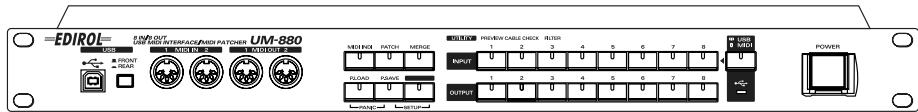
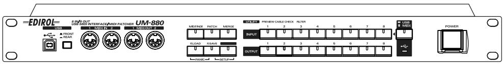
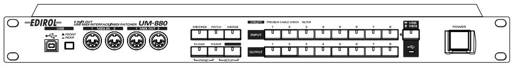
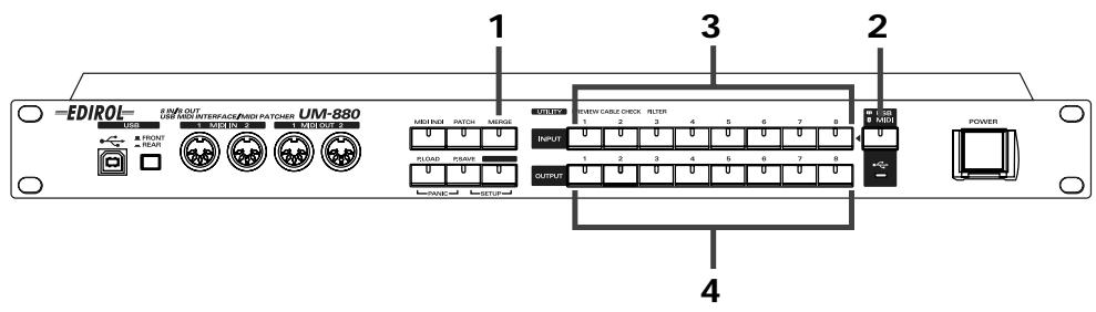
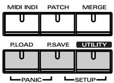
| Front Panel | Buttons: INPUT 1-8, OUTPUT 1-8, MIDI INDI, PATCH, MERGE, P. SAVE, P. LOAD, UTILITY, USB/MIDI, power switch |
| Rear Panel | MIDI IN/OUT connectors 3-8, rear USB, power socket, ground terminal |
| Maintenance and Cleaning | Clean with a soft, dry cloth; do not use solvents |
| Safety | Use only the supplied power cord; do not open the device; keep away from water |
| Spare Parts and Repairability | Not available; contact EDIROL customer service |
| General Information | 8x8 MIDI interface with FPT technology for fast transmission; compatible with Windows/Mac |
Frequently Asked Questions - UM-880 EDIROL
User questions about UM-880 EDIROL
0 question about this device. Answer the ones you know or ask your own.
Ask a new question about this device
Download the instructions for your MIDI Interface in PDF format for free! Find your manual UM-880 - EDIROL and take your electronic device back in hand. On this page are published all the documents necessary for the use of your device. UM-880 by EDIROL.
USER MANUAL UM-880 EDIROL
8 IN/8 OUT USB MIDI INTERFACE/MIDI Patcher
UM-880
We'd like to take a moment to thank you for purchasing the UM-880 (32 Channel USB MIDI Interface).
This document explains how to set up the UM-880 system. To avoid problems and enjoy optimal performance, please carefully follow the setup instructions described in this document.
Before using this unit, carefully read the sections entitled: "USING THE UNIT SAFELY" (P. 3, 4) and "IMPORTANT NOTES" (P. 5, 6). These sections provide important information concerning the proper operation of the unit. Additionally, in order to feel assured that you have gained a good grasp of every feature provided by your new unit, this manual should be read in its entirety. The manual should be saved and kept on hand as a convenient reference.

ATTENTION
CAUTION
RISK OF ELECTRIC SHOCK DO NOT OPEN

RISQUE DE CHOC ELECTRIQUE NE PAS OUVRIR
CAUTION: TO REDUCE THE RISK OF ELECTRIC SHOCK, DO NOT REMOVE COVER (OR BACK).
NO USER-SERVICEABLE PARTS INSIDE.
REFER SERVICING TO QUALIFIED SERVICE PERSONNEL.

The lightning flash with arrowhead symbol, within an equilateral triangle, is intended to alert the user to the presence of uninsulated "dangerous voltage" within the product's enclosure that may be of sufficient magnitude to constitute a risk of electric shock to persons.

The exclamation point within an equilateral triangle is intended to alert the user to the presence of important operating and maintenance (servicing) instructions in the literature accompanying the product.
INSTRUCTIONS PERTAINING TO A RISK OF FIRE, ELECTRIC SHOCK, OR INJURY TO PERSONS.
IMPORTANT SAFETY INSTRUCTIONS SAVE THESE INSTRUCTIONS
WARNING - When using electric products, basic precautions should always be followed, including the following:
- Read these instructions.
- Keep these instructions.
- Heed all warnings.
- Follow all instructions.
- Do not use this apparatus near water.
- Clean only with a dry cloth.
- Do not block any of the ventilation openings. Install in accordance with the manufacturers instructions.
- Do not install near any heat sources such as radiators, heat registers, stoves, or other apparatus (including amplifiers) that produce heat.
-
Do not defeat the safety purpose of the polarized or grounding-type plug. A polarized plug has two blades with one wider than the other. A grounding type plug has two blades and a third grounding prong. The wide blade or the third prong are provided for your safety. When the provided plug does not fit into your outlet, consult an electrician for replacement of the obsolete outlet.
-
Protect the power cord from being walked on or pinched particularly at plugs, convenience receptacles, and the point where they exit from the apparatus.
- Only use attachments/accessories specified by the manufacturer.
- Never use with a cart, stand, tripod, bracket, or table except as specified by the manufacturer, or sold with the apparatus. When a cart is used, use caution when moving the cart/apparatus combination to avoid injury from tip-over.
- Unplug this apparatus during lightning storms or when unused for long periods of time.
- Refer all servicing to qualified service personnel. Servicing is required when the apparatus has been damaged in any way, such as power-supply cord or plug is damaged, liquid has been spilled or objects have fallen into the apparatus, the apparatus has been exposed to rain or moisture, does not operate normally, or has been dropped.
For the U.K.
WARNING: THIS APPARATUS MUST BE EARTHED
IMPORTANT: THE WIRES IN THIS MAINS LEAD ARE COLOURED IN ACCORDANCE WITH THE FOLLOWING CODE. GREEN-AND-YELLOW: EARTH, BLUE: NEUTRAL, BROWN: LIVE
As the colours of the wires in the mains lead of this apparatus may not correspond with the coloured markings identifying the terminals in your plug, proceed as follows:
The wire which is coloured GREEN-AND-YELLOW must be connected to the terminal in the plug which is marked by the letter E or by the safety earth symbol or coloured GREEN or GREEN-AND-YELLOW.
The wire which is coloured BLUE must be connected to the terminal which is marked with the letter N or coloured BLACK.
The wire which is coloured BROWN must be connected to the terminal which is marked with the letter L or coloured RED.

USING THE UNIT SAFELY
INSTRUCTIONS FOR THE PREVENTION OF FIRE, ELECTRIC SHOCK, OR INJURY TO PERSONS
About WARNING and CAUTION Notices
| ▲WARNING | Used for instructions intended to alert the user to the risk of death or severe injury should the unit be used improperly. |
| ▲CAUTION | Used for instructions intended to alert the user to the risk of injury or material damage should the unit be used improperly. * Material damage refers to damage or other adverse effects caused with respect to the home and all its furnishings, as well to domestic animals or pets. |
About the Symbols
| △ | The △ symbol alerts the user to important instructions or warnings. The specific meaning of the symbol is determined by the design contained within the triangle. In the case of the symbol at left, it is used for general cautions, warnings, or alerts to danger. |
| ◎ | The ⊙ symbol alerts the user to items that must never be carried out (are forbidden). The specific thing that must not be done is indicated by the design contained within the circle. In the case of the symbol at left, it means that the unit must never be disassembled. |
| ◆ | The ● symbol alerts the user to things that must be carried out. The specific thing that must be done is indicated by the design contained within the circle. In the case of the symbol at left, it means that the power-cord plug must be unplugged from the outlet. |
ALWAYS OBSERVE THE FOLLOWING
WARNING
Before using this unit, make sure to read the instructions below, and the Owner's Manual.

- Do not open or perform any internal modifications on the unit.

- Do not attempt to repair the unit, or replace parts within it (except when this manual provides specific instructions directing you to do so). Refer all servicing to your retailer, the nearest Roland / EDIROL Service Center, or an authorized Roland / EDIROL distributor, as listed on the "Information" page.

- Never use or store the unit in places that are:

- Subject to temperature extremes (e.g., direct sunlight in an enclosed vehicle, near a heating duct, on top of heat-generating equipment); or are

- Damp (e.g., baths, washrooms, on wet floors); or are
- Humid; or are
- Exposed to rain; or are
- Dusty; or are
-
Subject to high levels of vibration.
-
This unit should be used only with a rack or stand that is recommended by Roland.

WARNING
- When using the unit with a rack or stand recommended by Roland, the rack or stand must be carefully placed so it is level and sure to remain stable. If not using a rack or stand, you still need to make sure that any location you choose for placing the unit provides a level surface that will properly support the unit, and keep it from wobbling.

- The unit should be connected to a power supply only of the type described in the operating instructions, or as marked on the unit.

- Do not excessively twist or bend the power cord, nor place heavy objects on it. Doing so can damage the cord, producing severed elements and short circuits. Damaged cords are fire and shock hazards!

- Do not allow any objects (e.g., flammable material, coins, pins); or liquids of any kind (water, soft drinks, etc.) to penetrate the unit.

- In households with small children, an adult should provide supervision until the child is capable of following all the rules essential for the safe operation of the unit.


WARNING
- Protect the unit from strong impact. (Do not drop it!)

- Do not force the unit's power-supply cord to share an outlet with an unreasonable number of other devices. Be especially careful when using extension cords—the total power used by all devices you have connected to the extension cord's outlet must never exceed the power rating (watts/amperes) for the extension cord. Excessive loads can cause the insulation on the cord to heat up and eventually melt through.

- Before using the unit in a foreign country, consult with your retailer, the nearest Roland Service Center, or an authorized Roland distributor, as listed on the "Information" page.

DO NOT play a CD-ROM disc on a conventional audio CD player. The resulting sound may be of a level that could cause permanent hearing loss. Damage to speakers or other system components may result.

CAUTION
- The unit should be located so that its location or position does not interfere with its proper ventilation.

- Always grasp only the plug on the power-supply cord when plugging into, or unplugging from, an outlet or this unit.

- Try to prevent cords and cables from becoming entangled. Also, all cords and cables should be placed so they are out of the reach of children.

- Never climb on top of, nor place heavy objects on the unit.

- Never handle the power cord or its plugs with wet hands when plugging into, or unplugging from, an outlet or this unit.

CAUTION
- Before moving the unit, disconnect the power plug from the outlet, and pull out all cords from external devices.

- Before cleaning the unit, turn off the power and unplug the power cord from the outlet.

- Whenever you suspect the possibility of lightning in your area, pull the plug on the power cord out of the outlet.

- Should you remove screws, make sure to put them in a safe place out of children's reach, so there is no chance of them being swallowed accidentally.

IMPORTANT NOTES
In addition to the items listed under "IMPORTANT SAFETY INSTRUCTIONS" and "USING THE UNIT SAFELY" on pages 3 and 4, please read and observe the following:
Power Supply
- Do not use this unit on the same power circuit with any device that will generate line noise (such as an electric motor or variable lighting system).
- Before connecting this unit to other devices, turn off the power to all units. This will help prevent malfunctions and/or damage to speakers or other devices.
■ Placement
- This device may interfere with radio and television reception. Do not use this device in the vicinity of such receivers.
- Do not expose the unit to direct sunlight, place it near devices that radiate heat, leave it inside an enclosed vehicle, or otherwise subject it to temperature extremes. Excessive heat can deform or discolor the unit.
- To avoid possible breakdown, do not use the unit in a wet area, such as an area exposed to rain or other moisture.
■ Maintenance
- For everyday cleaning wipe the unit with a soft, dry cloth or one that has been slightly dampened with water. To remove stubborn dirt, use a cloth impregnated with a mild, non-abrasive detergent. Afterwards, be sure to wipe the unit thoroughly with a soft, dry cloth.
- Never use benzine, thinners, alcohol or solvents of any kind, to avoid the possibility of discoloration and/or deformation.
Additional Precautions
- Please be aware that the contents of memory can be irretrievably lost as a result of a malfunction, or the improper operation of the unit. To protect yourself against the risk of loosing important data, we recommend that you periodically save a backup copy of important data you have stored in the unit's memory in another MIDI device (e.g., a sequencer).
- Unfortunately, it may be impossible to restore the contents of data that was stored in another MIDI device (e.g., a sequencer) once it has been lost. Roland Corporation assumes no liability concerning such loss of data.
- Use a reasonable amount of care when using the unit's buttons, sliders, or other controls; and when using its jacks and connectors. Rough handling can lead to malfunctions.
- When connecting / disconnecting all cables, grasp the connector itself—never pull on the cable. This way you will avoid causing shorts, or damage to the cable's internal elements.
- A small amount of heat will radiate from the unit during normal operation.
-
To avoid disturbing your neighbors, try to keep the unit's volume at reasonable levels. You may prefer to use headphones, so you do not need to be concerned about those around you (especially when it is late at night).
-
When you need to transport the unit, package it in the box (including padding) that it came in, if possible. Otherwise, you will need to use equivalent packaging materials.
■ Handling CD-ROMs
-
Avoid touching or scratching the shiny underside (encoded surface) of the disc. Damaged or dirty CD-ROM discs may not be read properly. Keep your discs clean using a commercially available CD cleaner.
-
Microsoft and Windows are registered trademarks of Microsoft Corporation.
- Windows® Me is known officially as: "Microsoft® Windows® Millennium Edition operating system."
- Windows® 98 is known officially as: "Microsoft® Windows® 98 operating system."
- Windows® 2000 is known officially as: "Microsoft® Windows® 2000 operating system."
- Apple, Macintosh and MacOS are registered trademark of Apple Computer, Inc.
- OMS is a registered trademark of Opcode Systems, Inc.
- All product names mentioned in this document are trademarks or registered trademarks of their respective owners.
Table des matieres
USING THE UNIT SAFELY 3
IMPORTANT NOTES 5
Introduction 8
Features of the UM-880 8
Contents of the Package 9
When Connecting Multiple UM-880 Units (Windows Me/98) 58
Block Diagram 60
Main Specifications 61
Introduction
Features of the UM-880
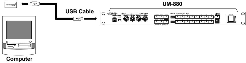
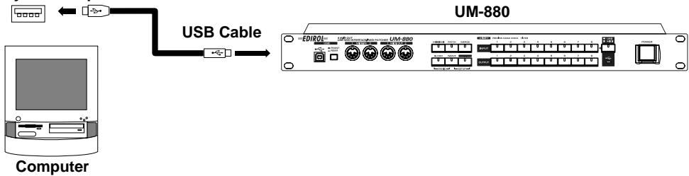
The UM-880 is a USB MIDI interface that connects to your computer via USB.

■ 8 in/8 out USB MIDI interface
With eight sets of MIDI input/output ports, the UM-880 lets you simultaneously control a maximum of 128 channels. Connection to your computer is easy--simply connect a USB cable and you're done. Support for hot-plugging allows you to connect or disconnect the UM-880 even while your computer is turned on. Up to four UM-880 units can be used simultaneously, expanding your system to 512 channels.
■ Hardware-based MIDI Patcher functionality
The UM-880 features hardware MIDI patcher functionality, which uses HDMR technology to guarantee low latency. MIDI can be routed directly, simply by pressing the panel buttons; and there are none of the complicated settings that are all too common on software patchers. When a computer is not connected, the UM-880 can also be used as a stand-alone MIDI patcher.
■ High-speed transmission of MIDI data
FPT technology allows optimal transmission of MIDI data via USB, for high-speed and stable transmission of data. Performance will always be optimal, regardless of the applications you use.
Maximum of eight patches can be stored
Up to eight separate sets of input/output connections that you specify can be stored in memory.
Easy USB connection to your computer
The UM-880 can be connected even when your computer is turned on. You can also switch between the USB connectors on the front and rear panels.

If you are using Windows 2000, it is not possible to use two or more UM-880 units simultaneously.

HDMR (Hardware Direct MIDI Routing): Connects port to port in hardware, guaranteeing low latency.

FPT (Fast Processing Technology for MIDI transmission): Makes effective use of the USB bandwidth according to the amount of transmitted MIDI data, performing optimal MIDI data processing at all times.
Contents of the Package
The box in which the UM-880 was shipped should contain the following items. After opening the box, first check to make sure that all the items are included. If any items are missing, please contact the store where you purchased the UM-880.
UM-880 USB MIDI Interface
■ "UM-880 Driver CD-ROM" (one disk)
- Be sure to read the Readme_e.txt file found on the UM-880 Driver CD-ROM. The Readme_e.txt file contains additional information regarding changes or updates that may have occurred after this manual was printed.
USB Cable (2 m, one cable)

■ UM-880 Owner's Manual (this document)

Sounds and Multimedia

Multimedia
NOTE
USB Connector of your Computer

Sounds and Multimedia

This installation requires your computer to restart after installing this software. Click Continue to automatically quit all other running applications. Click Cancel to leave your disks untouched.
Cancel
4

USB Connector of your Computer

UM-880 FM Driver-E Installer

This installation requires your computer to restart after installing this software. Click Continue to automatically quit all other running applications. Click Cancel to leave your disks untouched.
Cancel
1 Continue

Installation was successful. You have installed software which requires you to restart your computer. If you are finished, click Restart, or if you wish to perform additional installations, click Continue.

Paramètres FreeMIDI

USB Connector of your Computer

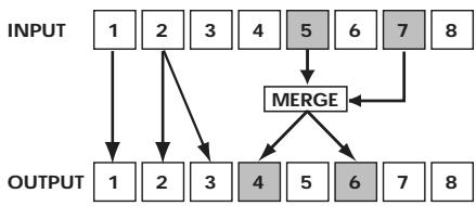
* The Patch mode settings for 4 and 6 will be invalid.
Panic (P.LOAD + P.SAVE)
Si la boîte de dialogue indique “ The software needed to use the USB device “Unknown Device” cannot be found. Please refer to the device documentation to install the necessary software ”, cliquez sur [OK].
Si la boîte de dialogue indique " Software needed for the USB device "Unnamed Device" is not available. Would you like to look for the software on the Internet? ", cliquez sur [Annulerl].
pp = memory number: 01H - 08H (Memory 1 - Memory 8)
-
Used to switch patches.
-
When using Patch Change or system exclusive to change the current patch, the UM-880 will require up to 200 milliseconds of processing time in order to process the changes. When changing the current patch of the UM-880 from a sequencer, please allow an interval of 200ms or more before the next data.
System Exclusive Message
Data transmission
The UM-880 can use Exclusive messages to transmit internal settings to other devices. There are two types of Exclusive data transmission; Individual Parameter Transmission (p. 52) in which single parameters are transmitted one by one, and Bulk Dump Transmission (p. 54) in which a large amount of data is transmitted at once.
Request data 1 RQ1 (11H)
This message requests the other device to send data. The Address and Size determine the type and amount of data to be sent. There are two types of request; Individual Parameter Request which requests data for an individual parameter, and Bulk Dump Request which requests a large amount of data at once. In either case, the "Data Request 1 (RQ1)" message format is used, and the Address and Size included in the message determine the type and amount of data that is desired. For Individual Parameter Request, Individual Parameter Transmission (p. 52)
For Bulk Dump Request, refer to Bulk Dump (p. 54)
When a Data Request message is received, if the device is ready to transmit data and if the address and size are appropriate, the requested data will be transmitted as a "Data Set 1 (DT1)" message. If not, nothing will be transmitted.
| Status | Data byte | Status |
| F0H | 41H, 10H, 00H, 49H, 11H, 0AH, 00H, 00H, ssH, sum | F7H |
Byte Explanation
F0H Exclusive status
41H ID number (Roland)
10H Device ID
00H UM-880 ID MSB
49H UM-880 ID LSB
11H Command ID (RQ1)
0AH Address MSB: upper byte of the starting address of the requested data
00H Address LSB: lower byte of the starting address of the requested data
00H Size MSB
ssH Size LSB
sum Checksum
F7H EOX (End Of Exclusive)
-
The amount of data that can be transmitted at one time will depend on the type of data, and data must be requested using a specific starting address and size. Refer to the Address and Size listed in Individual Parameter Transmission (p. 52)
-
Regarding the checksum, please refer to Section 5 (p. 56)
Data set 1 DT1 (12H)
This is the message that actually performs data transmission, and is used when you wish to transmit the data.
| Status | Data byte | Status |
| F0H | 41H, 10H, 00H, 49H, 12H, aaH, bbH, ccH, sum | F7H |
Byte Explanation
F0H Exclusive status
41H ID number (Roland)
10H Device ID
00H UM-880 ID MSB
49H UM-880 ID LSB
12H Command ID (DT1)
aaH Address MSB: upper byte of the starting address of the transmitted data
bbH Address LSB: lower byte of the starting address of the transmitted data
ccH Data: the actual data to be transmitted. Multiple bytes of data are transmitted starting from the address.
:
sum Checksum
F7H EOX (End Of Exclusive)
- The amount of data that can be transmitted at one time depends on the type of data, and data can be received only from the specified starting address and size. Refer to the Address and Size given in Individual Parameter Transmission (p. 52)
- Data larger than 128 bytes must be divided into packets of 128 bytes or less. If "Data Set 1" is transmitted successively, there must be an interval of at least 40 ms between packets.
- Regarding the checksum, please refer to Section 5 (p.56)
Bulk Dump Format
Internal parameters of the UM-880 will be transmitted and received.
| Status | Data byte | Status |
| F0H | 41H, 10H, 00H, 49H, 12H, 0AH, 00H, Data0,..., Data24, sum | F7H |
Byte Explanation
F0H Exclusive status
41H ID number (Roland)
10H Device ID
00H UM-880 ID MSB
49H UM-880 ID LSB
12H Command ID (DT1)
0AH Address MSB: upper byte of the starting address of the transmitted data
00H Address LSB: lower byte of the starting address of the transmitted data
Data0
:
Data24
sum Checksum
F7H EOX (End Of Exclusive)
- The data of the region specified by Data 0 is transmitted in succession from Data 1 through Data 24. For details, refer to p. 54.
2. Transmit data
■Channel Voice Messages
Note off
| Status | 2nd byte | 3rd byte |
| 8nH | kkH | 40H |
n = MIDI channel number: 0H-FH (Ch.1-16)
aa = note number: 00H - 7FH (0 - 127)
- Transmitted when Panic is executed.
- Transmitted for all channels and all notes (00H--7FH).
- A total of 16 channels x 128 notes = 1970 note-off messages will be transmitted.
Note off (A4)
| Status | 2nd byte | 3rd byte |
80H 45H 40H
- Transmitted during Preview.
Note on
| Status | 2nd byte | 3rd byte |
| 90H | 45H | 64H |
- Transmitted during Preview.
■Channel Mode Messages
All Sounds Off (Controller number 120)
| Status | 2nd byte | 3rd byte |
| BnH | 78H | 00H |
n = MIDI channel number: 0H-FH (Ch.1-16)
- When this message is received, all currently sounding notes on the corresponding channel will be turned off immediately.
Reset All Controllers (Controller number 121)
| Status | 2nd byte | 3rd byte |
| BnH | 79H | 00H |
n = MIDI channel number: 0H -FH (Ch.1-16)
- Transmitted when changing patches and when Panic is executed.
- When this message is received, the following controllers will be set to their reset values.
| Controller | Reset value |
| Pitch Bend Change | +/-0 (center) |
| Polyphonic Key Pressure | 0 (off) |
| Channel Pressure | 0 (off) |
| Modulation | 0 (off) |
| Expression | 127 (max) |
| Hold 1 | 0 (off) |
| Portamento | 0 (off) |
| Sostenuto | 0 (off) |
| Soft | 0 (off) |
| RPN | unset; previously set data will not change |
| NRPN | unset; previously set data will not change |
All Notes Off (Controller number 123)
| Status | 2nd byte | 3rd byte |
| BnH | 7BH | 00H |
n = MIDI channel number: 0H-FH (Ch.1-16)
- Transmitted when changing patches and when Panic is executed.
- When All Notes Off is received, all notes on the corresponding channel will be turned off. However, if Hold 1 or Sostenuto is ON, the sound will be continued until these are turned off.
System Realtime Message
Timing Clock
Status
F8H
- Transmitted when checking a cable.
- Transmitted continuously to MIDI OUT 1/2.
Active Sensing
Status
FEH
- Transmitted constantly at intervals of approximately 250 ms.
Data set 1 DT1 (12H)
This is the message that actually performs data transmission, and is used when you wish to transmit the data.
| Status | Data byte | Status |
| F0H | 41H, 10H, 00H, 49H, 12H, aaH, bbH, ccH, sum | F7H |
Byte Explanation
| F0H | Exclusive status | |
| 41H | ID number (Roland) | |
| 10H | Device ID | |
| 00H | UM-880 ID MSB | |
| 49H | UM-880 ID LSB | |
| 12H | Command ID | (DT1) |
| aaH | Address MSB: | upper byte of the starting address of the transmitted data |
| bbH | Address LSB: | lower byte of the starting address of the transmitted data |
| ccH | Data: | the actual data to be transmitted. Multiple bytes of data are transmitted starting from the address. |
| : | : | |
| sum | Checksum | |
| F7H | EOX | (End Of Exclusive) |
- The amount of data that can be transmitted at one time depends on the type of data, and data can be received only from the specified starting address and size. Refer to the Address and Size given in Individual Parameter Transmission (p. 52)
- Data larger than 128 bytes must be divided into packets of 128 bytes or less. If "Data Set 1" is transmitted successively, there must be an interval of at least 40 ms between packets.
- Regarding the checksum, please refer to Section 5 (p.56)
Bulk Dump Format
| Status | Data byte | Status |
| F0H | 41H, 10H, 00H, 49H, 12H, 0AH, 00H, Data0,...,Data24, sum | F7H |
| Byte | Explanation | |
| F0H | Exclusive status | |
| 41H | ID number (Roland) | |
| 10H | Device ID | |
| 00H | UM-880 ID MSB | |
| 49H | UM-880 ID LSB | |
| 12H | Command ID (DT1) | |
| 0AH | Address MSB: upper byte of the starting address of the transmitted data | |
| 00H | Address LSB: lower byte of the starting address of the transmitted data | |
| Data0 | ||
| : | : | |
| Data24 | ||
| sum | Checksum | |
| F7H | EOX (End Of Exclusive) |
- The data of the region specified by Data 0 is transmitted in succession from Data 1 through Data 24.
3. Individual Parameter Transmission
(Model ID=49H)
Individual Parameter Transmission transmits data (or requests data) for one parameter as one Exclusive message (one packet of "F0....F7"). In Individual Parameter Transmission, you must use the Address and Size listed in the following "Parameter Address Map".
Address Block map
An outlined address map of the Individual Parameter Transmission is as follows;
| Address(H) | Block |
| 00 00 | Current Patch |
| 01 00 | Memory 1 |
| 02 00 | Memory 2 |
| : | |
| 08 00 | Memory 8 |
| 09 00 | System Setup |
Parameter address map
This map lists the addresses, areas whose data can be specified, parameters (data types), and explanations that apply when the exclusive messages "Data request 1" and "Data set 1" are used to transmit data.
Data set parameter
| Address(H) | Data(H) | Parameter | Explanation |
| 00 00 | 00 | CURRENT MIDI OUT1 PATCH | NO ASSIGN |
| 00 00 | 01 | CURRENT MIDI OUT1 PATCH | MIDI IN 1 |
| : | : | : | : |
| 00 00 | 08 | CURRENT MIDI OUT1 PATCH | MIDI IN 8 |
| 00 00 | 09 | CURRENT MIDI OUT1 PATCH | USB IN 1 |
| : | : | : | : |
| 00 00 | 10 | CURRENT MIDI OUT1 PATCH | USB IN 8 |
| 00 00 | 11 | CURRENT MIDI OUT1 PATCH | MERGE |
| 00 01 | 00 | CURRENT MIDI OUT2 PATCH | NO ASSIGN |
| : | : | : | : |
| 00 07 | 11 | CURRENT MIDI OUT8 PATCH | MERGE |
| 00 08 | 00 | CURRENT USB 1 MERGE ENABLE | MERGE DISABLE |
| 00 08 | 01 | CURRENT USB 1 MERGE ENABLE | MERGE ENABLE |
| 00 09 | 00 | CURRENT USB 2 MERGE ENABLE | MERGE DISABLE |
| : | : | : | : |
| 00 0F | 01 | CURRENT USB 8 MERGE ENABLE | MERGE ENABLE |
| 00 10 | 00 | CURRENT MIDI IN 1 MERGE ENABLE | MERGE DISABLE |
| 00 10 | 01 | CURRENT MIDI IN 1 MERGE ENABLE | MERGE ENABLE |
| 00 11 | 00 | CURRENT MIDI IN 2 MERGE ENABLE | MERGE DISABLE |
| : | : | : | : |
| 00 17 | 01 | CURRENT MIDI IN 8 MERGE ENABLE | MERGE ENABLE |
| 01 00 | 00 | MEMORY 1 MIDI OUT1 PATCH | NO ASSIGN |
| : | : | : | : |
| 01 17 | 01 | MEMORY 1 MIDI IN 8 MERGE ENABLE | MERGE ENABLE |
| 02 00 | 00 | MEMORY 2 MIDI OUT1 PATCH | NO ASSIGN |
| : | : | : | : |
| 08 17 | 01 | MEMORY 8 MIDI IN 8 MERGE ENABLE | MERGE ENABLE |
| 09 00 | 00 | SYSTEM MIDI FILTER ENABLE NOTE | FILTER DISABLE |
| 09 00 | 01 | SYSTEM MIDI FILTER ENABLE NOTE | FILTER ENABLE |
| 09 01 | 00 | SYSTEM MIDI FILTER ENABLE Ax | FILTER DISABLE |
| 09 01 | 01 | SYSTEM MIDI FILTER ENABLE Ax | FILTER ENABLE |
| 09 02 | 00 | SYSTEM MIDI FILTER ENABLE Bx | FILTER DISABLE |
| 09 02 | 01 | SYSTEM MIDI FILTER ENABLE Bx | FILTER ENABLE |
| 09 03 | 00 | SYSTEM MIDI FILTER ENABLE Cx | FILTER DISABLE |
| 09 03 | 01 | SYSTEM MIDI FILTER ENABLE Cx | FILTER ENABLE |
| 09 04 | 00 | SYSTEM MIDI FILTER ENABLE Dx | FILTER DISABLE |
| 09 04 | 01 | SYSTEM MIDI FILTER ENABLE Dx | FILTER ENABLE |
| 09 05 | 00 | SYSTEM MIDI FILTER ENABLE Ex | FILTER DISABLE |
| 09 05 | 01 | SYSTEM MIDI FILTER ENABLE Ex | FILTER ENABLE |
| 09 06 | 00 | SYSTEM MIDI FILTER ENABLE SYS REAL/ SYS COM | FILTER DISABLE |
| 09 06 | 01 | SYSTEM MIDI FILTER ENABLE SYS REAL/ SYS COM | FILTER ENABLE |
| 09 07 | 00 | SYSTEM MIDI FILTER ENABLE SYS EX | FILTER DISABLE |
| 09 07 | 01 | SYSTEM MIDI FILTER ENABLE SYS EX | FILTER ENABLE |
| 09 08 | 00 | SYSTEM USB Tx1 ENABLE | Tx DISABLE |
| 09 08 | 01 | SYSTEM USB Tx1 DISABLE | Tx ENABLE |
| 09 09 | 00 | SYSTEM USB Tx2 ENABLE | Tx DISABLE |
| : | : | : | : |
| 09 0F | 01 | SYSTEM USB Tx8 DISABLE | Tx ENABLE |
| 09 10 | 00 | SYSTEM MIDI CNT PORT | NO ASSIGN |
| 09 10 | 01 | SYSTEM MIDI CNT PORT | MIDI IN/OUT 1 |
| : | : | : | : |
| 09 10 | 08 | SYSTEM MIDI CNT PORT | MIDI IN/OUT 8 |
| 09 11 | 00 | SYSTEM USB DRIVER SEL | GENERIC |
| 09 11 | 01 | SYSTEM USB DRIVER SEL | ORIGINAL |
| 09 12 | 00 | SYSTEM CURRENT RESUME SEL | DO NOT RESUME CURRENT |
| 09 12 | 01 | SYSTEM CURRENT RESUME SEL | RESUME CURRENT |
4. Bulk Dump
By using Bulk Dump, a large amount of data can be transferred at once. This is used to store settings for an entire device onto a computer or sequencer. In order to make the UM-880 transmit a bulk dump, send it the bulk dump request messages listed below. Bulk dump requests use the Data Request 1 (RQ1) format, but unlike the case when transmitting individual parameters, the "size" in the request message does not specify the data size, but rather is used to specify the contents of the data. For the actual contents of the data corresponding to each size, refer to the "Parameter Dump" section.
When the UM-880 receives a bulk dump request, it will transmit a bulk dump in the format described below.
Parameter dump
Parameter dump request
This is a command that requests a set of parameter data, and uses "Data Request 1 (RQ1)" format. The Size specifies the requested data contents.
| Address(H) | Size(H) | Parameter |
| 0A 00 | 00 00 | CURRENT BULK DUMP |
| 0A 00 | 00 01 | MEMORY1 BULK DUMP |
| 0A 00 | 00 02 | MEMORY2 BULK DUMP |
| 0A 00 | 00 03 | MEMORY3 BULK DUMP |
| 0A 00 | 00 04 | MEMORY4 BULK DUMP |
| 0A 00 | 00 05 | MEMORY5 BULK DUMP |
| 0A 00 | 00 06 | MEMORY6 BULK DUMP |
| 0A 00 | 00 07 | MEMORY7 BULK DUMP |
| 0A 00 | 00 08 | MEMORY8 BULK DUMP |
| 0A 00 | 00 09 | SYSTEM BULK DUMP |
| 0A 00 | 00 0A | ALL PATCH BULK DUMP |
| 0A 00 | 00 0B | CURRENT & ALL PATCH & SYSTEM BULK DUMP |
Bulk dump format parameters
| Data 0 (Bulk Address) | Data Line (1-24) | Description |
| 00H: Current | Data 1: MIDI OUT 1 Patch | Connection of MIDI OUT 00H: No Assign 01H: MIDI IN 1 |
| 01H: Memory 1 | Data 8: MIDI OUT 8 Patch | 08H: MIDI IN 8 |
| 08H: Memory 8 | 09H: USB IN 1 | |
| * "Current" is the current patch data | Data 9: USB 1 Merge Enable | 10H: USB IN 8 |
| * "Memory" is the patch data stored in the UM-880 | Data 16: USB 8 Merge Enalbe | 11H: Merge |
| Data 17: MIDI IN 1 Merge Enable | USB# Merge Enable | |
| Data 24: MIDI IN 8 Merge Enalbe | 00H: Merge Disable 01H: Merge Enable | |
| MIDI IN# Merge Enable | ||
| 00H: Merge Disable | ||
| 01H: Merge Enable |
- When data dumped by the UM-880 is loaded back into the UM-880, be aware that if the packets are transmitted in a different order, or if the time interval between packets is different, or if other messages are inserted between packets, the data may fail to be recognized correctly.
| Data 0(Bulk Address) | Data Line (1-24) | Description |
| 09H :System | Data 1 :MIDI Filter Enable NOTE | MIDI Filter Enable00H : Filter Disable01H : Filter Enable |
| Data 2 :MIDI Filter Enable Ax | ||
| Data 3 :MIDI Filter Enable Bx | ||
| Data 4 :MIDI Filter Enable Cx | ||
| Data 5 :MIDI Filter Enable Dx | ||
| Data 6 :MIDI Filter Enable Ex | ||
| Data 7 :MIDI Filter Enable SysReal/ SysCom | ||
| Data 8 :MIDI Filter Enable SysEx | ||
| Data 9 : USB Tx1 Enable| Data 16 : USB Tx8 Enable | USB Tx Enable00H : USB Tx Disable01H : USB Tx Enalbe | |
| Data 17 :MIDI Cnt Port | MIDI Control Port00H : No Assign01H - 08H :MIDI IN/OUT 1 -8 | |
| Data 18 :USB Driver Sel | USB Driver Select00H : Generic01H : Original | |
| Data 19 :Current Resume Sel | Currnet Resume Select00H : Do Not Resume Current01H : Resume Current | |
| Data 20 - Data 24 | Reserved00H : |
5. Supplementary material
- Decimal and Hexadecimal table
(An "H" is appended to the end of numbers in hexadecimal notation.)
In MIDI documentation, data values and addresses/sizes of Exclusive messages, etc. are expressed as hexadecimal values for each 7 bits.
The following table shows how these correspond to decimal numbers.
| Dec. | Hex. | Dec. | Hex. | Dec. | Hex. | Dec. | Hex. |
| 0 | 00H | 32 | 20H | 64 | 40H | 96 | 60H |
| 1 | 01H | 33 | 21H | 65 | 41H | 97 | 61H |
| 2 | 02H | 34 | 22H | 66 | 42H | 98 | 62H |
| 3 | 03H | 35 | 23H | 67 | 43H | 99 | 63H |
| 4 | 04H | 36 | 24H | 68 | 44H | 100 | 64H |
| 5 | 05H | 37 | 25H | 69 | 45H | 101 | 65H |
| 6 | 06H | 38 | 26H | 70 | 46H | 102 | 66H |
| 7 | 07H | 39 | 27H | 71 | 47H | 103 | 67H |
| 8 | 08H | 40 | 28H | 72 | 48H | 104 | 68H |
| 9 | 09H | 41 | 29H | 73 | 49H | 105 | 69H |
| 10 | 0AH | 42 | 2AH | 74 | 4AH | 106 | 6AH |
| 11 | 0BH | 43 | 2BH | 75 | 4BH | 107 | 6BH |
| 12 | 0CH | 44 | 2CH | 76 | 4CH | 108 | 6CH |
| 13 | 0DH | 45 | 2DH | 77 | 4DH | 109 | 6DH |
| 14 | 0EH | 46 | 2EH | 78 | 4EH | 110 | 6EH |
| 15 | 0FH | 47 | 2FH | 79 | 4FH | 111 | 6FH |
| 16 | 10H | 48 | 30H | 80 | 50H | 112 | 70H |
| 17 | 11H | 49 | 31H | 81 | 51H | 113 | 71H |
| 18 | 12H | 50 | 32H | 82 | 52H | 114 | 72H |
| 19 | 13H | 51 | 33H | 83 | 53H | 115 | 73H |
| 20 | 14H | 52 | 34H | 84 | 54H | 116 | 74H |
| 21 | 15H | 53 | 35H | 85 | 55H | 117 | 75H |
| 22 | 16H | 54 | 36H | 86 | 56H | 118 | 76H |
| 23 | 17H | 55 | 37H | 87 | 57H | 119 | 77H |
| 24 | 18H | 56 | 38H | 88 | 58H | 120 | 78H |
| 25 | 19H | 57 | 39H | 89 | 59H | 121 | 79H |
| 26 | 1AH | 58 | 3AH | 90 | 5AH | 122 | 7AH |
| 27 | 1BH | 59 | 3BH | 91 | 5BH | 123 | 7BH |
| 28 | 1CH | 60 | 3CH | 92 | 5CH | 124 | 7CH |
| 29 | 1DH | 61 | 3DH | 93 | 5DH | 125 | 7DH |
| 30 | 1EH | 62 | 3EH | 94 | 5EH | 126 | 7EH |
| 31 | 1FH | 63 | 3FH | 95 | 5FH | 127 | 7FH |
- Decimal values such as MIDI channel, bank select, and program change are listed as one greater than the values given in the above table.
- A 7-bit byte can express data in the range of 128 steps. For data where greater precision is required, we must use two or more bytes. For example, two hexadecimal numbers aa bbH expressing two 7-bit bytes would indicate a value of aa x 128+bb.
- In the case of values which have a +/ - sign, 00H = -64 , 40H = +/ - 0 , and 7FH = +63 , so that the decimal expression would be 64 less than the value given in the above chart. In the case of two types, 0000H = -8192 , 4000H = +/ - 0 , and 7F7FH = +8191 . For example, if aa bbH were expressed as decimal, this would be aa bbH - 40 00H = aa x 128+bb - 64 x 128.
- Data marked "Use nibbled data" is expressed in hexadecimal in 4-bit units. A value expressed as a 2-byte nibble 0a 0bH has the value of a x 16+b.
From the preceding table, 5AH = 90
From the preceding table, since 12H = 18 and 34H = 52
18 × 128 + 52 = 2356
From the preceding table, since 0AH = 10,03H = 3,09H = 9,0DH = 13
((10 × 16 + 3) × 16 + 9) × 16 + 13 = 41885
16) 1258
16) 78...10
16) 4...14
0...4
Since from the preceding table, 0 = 00H , 4 = 04H , 14 = 0EH , 10 = 0AH , the result is: 00 04 0E 0AH.
Examples of actual MIDI messages
9n is the Note-on status, and n is the MIDI channel number. Since 2H = 2 , 3EH = 62 and 5FH = 95 , this is a Note-on message with MIDI CH = 3 , note number 62 (note name is D4), and velocity 95.
CnH is the Program Change status, and n is the MIDI channel number. Since EH = 14 and 49H = 73 , this is a Program Change message with MIDI CH = 15, program number 74 (Flute in GS).
EnH is the Pitch Bend Change status, and n is the MIDI channel number. The 2nd byte (00H = 0) is the LSB and the 3rd byte (28H = 40) is the MSB, but Pitch Bend Value is a signed number in which 4000H (= 64× 12 + 80 = 8192) is 0, so this Pitch Bend Value is
2800H - 4000H = 40 × 12 + 80 - (64 × 12 + 80) = 5120 - 8192 = -3072
If the Pitch Bend Sensitivity is set to 2 semitones, -8192 (00 00H) will cause the pitch to change -200 cents, so in this case -200x(-3072)÷ (-8192) = -75 cents of Pitch Bend is being applied to MIDI channel 11.
BnH is the Control Change status, and n is the MIDI channel number. For Control Changes, the 2nd byte is the control number, and the 3rd byte is the value. In a case in which two or more messages consecutive messages have the same status, MIDI has a provision called "running status" which allows the status byte of the second and following messages to be omitted. Thus, the above messages have the following meaning.
B3 6400 MIDI ch.4, lower byte of RPN parameter number:00H
(B3) 6500 (MIDI ch.4) upper byte of RPN parameter number:00H
(B3) 06 0C (MIDI ch.4) upper byte of parameter value:0CH
(B3) 2600 (MIDI ch.4) lower byte of parameter value:00H
(B3) 647F (MIDI ch.4) lower byte of RPN parameter number:7FH
(B3) 657F (MIDI ch.4) upper byte of RPN parameter number:7FH
In other words, the above messages specify a value of 0C 00H for RPN parameter number 00 00H on MIDI channel 4, and then set the RPN parameter number to 7F 7FH.
RPN parameter number 00 00H is Pitch Bend Sensitivity, and the MSB of the value indicates semitone units, so a value of 0CH = 12 sets the maximum pitch bend range to + / - 12 semitones (1 octave). (On GS sound generators the LSB of Pitch Bend Sensitivity is ignored, but the LSB should be transmitted anyway (with a value of 0) so that operation will be correct on any device.)
Once the parameter number has been specified for RPN or NRPN, all Data Entry messages transmitted on that same channel will be valid, so after the desired value has been transmitted, it is a good idea to set the parameter number to 7F 7FH to prevent accidents. This is the reason for the (B3) 64 7F (B3) 65 7F at the end.
It is not desirable for performance data (such as Standard MIDI File data) to contain many events with running status as given in
It is also necessary that the RPN or NRPN parameter number setting and the value setting be done in the proper order. On some sequencers, events occurring in the same (or consecutive) clock may be transmitted in an order different than the order in which they were received. For this reason it is a good idea to slightly skew the time of each event (about 1 tick for TPQN = 96 , and about 5 ticks for TPQN = 480 ).
- TPQN: Ticks Per Quarter Note
Example of an Exclusive message and calculating a checksum
Roland Exclusive messages (RQ1, DT1) are transmitted with a checksum at the end (before F7) to make sure that the message was correctly received. The value of the checksum is determined by the address and data (or size) of the transmitted Exclusive message.
How to calculate the checksum (hexadecimal numbers are indicated by "H")
The checksum is a value derived by adding the address, size, and checksum itself and inverting the lower 7 bits.
Here's an example of how the checksum is calculated. We will assume that in the Exclusive message we are transmitting, the address is aa bb ccH and the data or size is dd ee ffH.
aa+bb+cc+dd+ee+ff = sum
sum ÷ 128 = quotient... remainder
128 - remainder = checksum
According to the Parameter address map (p. 53), the address for Memory 3 USB 1
Merge is 03 08H, and for Enable the value of the parameter should be 01H. Thus,
F0 41 10 00 49 12 03 08 02 F7
(1) (2) (3) (4) (5) (6) address data checksum (7)
(1) Exclusive Status, (2) ID (Roland), (3) Device ID (17),
(4) Model ID MSB, (5) Model ID LSB, (6) Command ID (DT1),
(7) End of Exclusive
Next, we calculate the checksum.
03H + 08H + 01H = 3 + 8 + 1 = 12 (sum)
12 (sum) ÷ 128 = 0 (quotient) ... 12 (remainder)
checksum = 128 - 12 (remainder) = 126 = 74H
This means that F0 41 10 00 49 12 03 08 02 74 F7 is the message we transmit.
According to the Parameter address map (p. 53), the address is 0A 00H and the size is 00 07H. Thus,
F0 41 10 00 49 11 0A00 0007 F7
(1) (2) (3) (4) (5) (6) address data checksum (7)
(1) Exclusive Status, (2) ID (Roland), (3) Device ID (17),
(4) Model ID MSB, (5) Model ID LSB (6) Command ID(RQ1),
(7) End of Exclusive
Next we calculate the checksum.
0AH + 00H + 00H + 07H = 10 + 0 + 0 + 7 = 17 (sum)
17 (sum) ÷ 128 = 0 (quotient) ... 17 (remainder)
checksum = 128 - 17 (remainder) = 111 = 6FH
This means that F0 41 10 00 49 11 0A 00 00 07 6F F7 is the message we transmit.
USB MIDI INTERFACE
Date: Sep. 10, 2001
Model UM-880
MIDI Implementation Chart
Version : 1.00
| Function... | Transmitted | Recognized | Remarks | |
| Basic Channel | Default Changed | X X | 1-16, OFF 1-16, OFF | Remembered even while the power is turned off. |
| Mode | Default Messages Altered | X X **** | Mode 3 X | |
| Note Number : | True Voice | O **** | 0-127 0-127 | |
| Velocity | Note On Note Off | O *1 (45H) O | X X | |
| After Touch | Key's Channel's | O *1 (90 v=64H) O *1 (8nH v=40H) | X X | |
| Pitch Bend | X | X | ||
| Control Change | 0-120 121 | O *2 *3 | X X | |
| Program Change : | True Number | X **** | 0-7 0-7 | |
| System Exclusive | O | O | ||
| System Common | : Song Position : Song Select : Tune Request | X X X | X X X | |
| System Real Time : | Clock Commands | O *4 X | X X | |
| Aux Messages | : All Sound Off : Reset All Controllers : Local On/Off : All Notes Off : Active Sensing : System Reset | *2 *3 (78H) *2 *3 (79H) X *2 *3 (7BH) O X | X X X X X X | |
| Notes | * 1 When PREVIEW is transmitted. * 4 CABLE CHECK * 2 When PANIC is transmitted. * 3 If connection is broken. | |||
Mode 1: OMNI ON, POLY
Mode 2:OMNI ON, MONO
Mode 3: OMNI OFF, POLY
Mode 4: OMNI OFF, MONO
O:Yes
X:No
Appendices
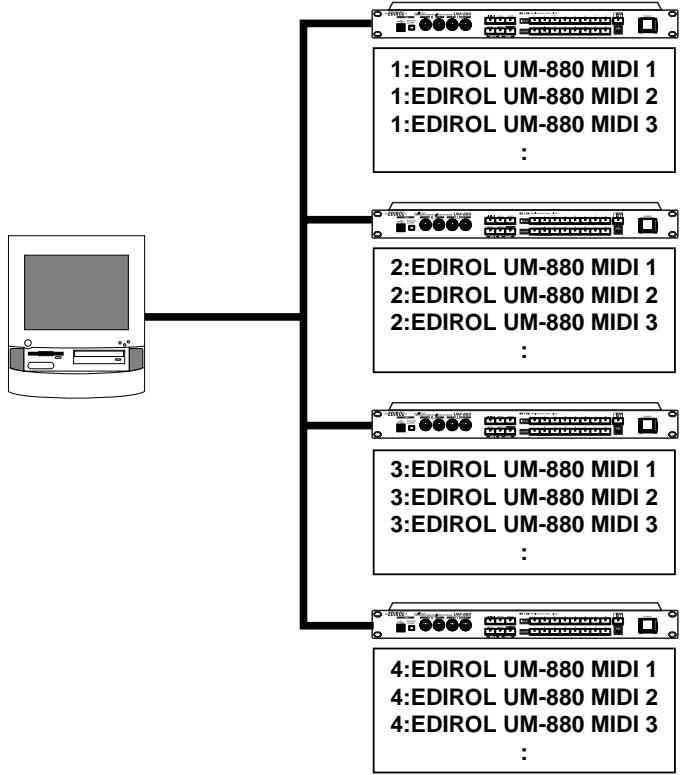
When Connecting Multiple UM-880 Units (Windows Me/98)
Up to four UM-880 units can be used simultaneously.(Windows Me/98 only)
Note of the Connecting Multiple UM-880 Units
When connecting multiple UM-880 units, the order of the MIDI device is assigned in the order (connection order) in which the computer recognized each UM-880 unit at the time of turning on the power of your computer or restarting the computer. Therefore, the order of the MIDI device may be changed when you restart the computer. In order to change the order of the MIDI device assigned to each UM-880, disconnect the USB cables connected to all UM-880 units (from the computer or USB hub).
Then connect the UM-880 that you want to be the first unit to the USB connector that had been connected to the UM-880 previously recognized as the first unit. Make connections in the same way for the second and subsequent units.
Windows Users
If you use multiple UM-880 units, device numbers will be added to the beginning of the device name to indicate the order (connection order) in which the computer recognized each UM-880 unit.
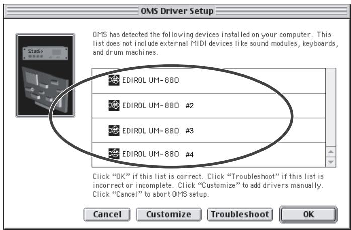
OMS Users on Macintosh
If you connect multiple UM-880 units and make OMS settings, multiple "EDIROL UM-880" items will appear, as shown in the illustration. Simply click
[OK], and follow the procedure to check all of the ports.
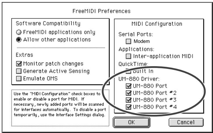
FreeMIDI Users on Macintosh
If you connect multiple UM-880 units and make FreeMIDI settings, multiple "UM-880 Port" items will appear, as shown in the illustration. Check all of them, and click [OK]. Then follow the procedure to continue making settings.
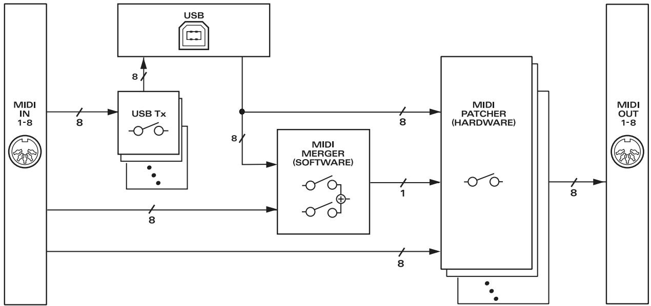
Block Diagram
■ SETUP mode
| SETUP | |
| INPUT 1 | USB Tx |
| INPUT 2 | BULK DUMP(CURRENT PATCH) |
| INPUT 3 | BULK DUMP(ALL PATCH) |
| INPUT 4 | CONTROL PORT SET |
| INPUT 5 | POWER ON CONDITION |
| INPUT 6 | PATCH CLEAR(CURRENT) |
| INPUT 7 | PATCH CLEAR(ALL) |
| INPUT 8 | FACTORY PRESET |
POWER ON CONDITION
| POWER ON CONDITION (SETUP-5) | |
| OUTPUT 1 | EDIROL ORIGINAL USB DRIVER |
| OUTPUT 2 | GENERIC USB DRIVER |
| OUTPUT 5 | RESUME CURRENT PATCH |
| OUTPUT 6 | NOT RESUME CURRENT PATCH |
■ UTILITY mode
| UTILITY | |
| INPUT 1 | MIDI OUT Preview |
| INPUT 2 | MIDI CABLE CHECK |
| INPUT 3 | MIDI EVENT FILTER |
MIDI EVENT FILTER
| MIDI EVENT FILTER (UTILITY-3) | |
| OUTPUT 1 | NOTE ON/NOTE OFF |
| OUTPUT 2 | POLYPHONIC KEY PRESSURE |
| OUTPUT 3 | CONTROL CHANGE |
| OUTPUT 4 | PROGRAM CHANGE |
| OUTPUT 5 | CHANNEL PRESSURE |
| OUTPUT 6 | PITCH BEND/MODULATION |
| OUTPUT 7 | REALTIME/CommonMESSAGE |
| OUTPUT 8 | SYSTEM EXCLUSIVE |
UM-880 error message list
1. When an exclusive message is received
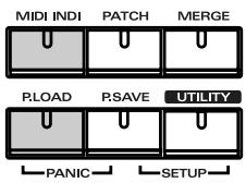
If one of the following errors occurs when the control port receives an exclusive message, the indicators that are shaded in the diagram at right will blink.
Check Sum Error
SysEx Format Error
- Value overflow Error
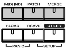
2. When the total volume of the merge port is boverloaded
If the total amount of data for the merge port exceeds the rated amount (31.25 kbps), the
indicators that are shaded in the diagram at right will blink.
3. When the data at a MIDI input port exceeds the rated amount
If the data at a MIDI input port exceeds the rated amount, the indicators that are shaded in the diagram at right will blink.
- The error indication will cease when you press any other button.
Main Specifications
UM-880: 128 Channel USB MIDI Interface
| Connectors | MIDI connectors (in: 8, out: 8)USB connector (front/rear, USB TYPE B) |
| Power Supply | AC117, 230, 240V |
| Power Consumption | 8W |
| Dimensions | 19 (W) x 9-1/8 (D) x 3-1/2(H) inches482 (W) x 231.4 (D) x 44 (H) mm |
| Weight | 2.4kg / 5 lbs 5 oz |
| Accessories | UM-880 Driver CD-ROMOwner's manualUSB cablePower cord |
- In the interest of product improvement, the specifications and/or appearance of this unit are subject to change without prior notice.
Information
When you need repair service, call your nearest EDIROL/Roland Service Center or authorized EDIROL/Roland distributor in your country as shown below.
-EDIROL
AUSTRALIA
EDIROL Australia Pty. Ltd.
72 Central Avenue
Oak Flats NSW 2529
AUSTRALIA
TEL: (02) 4257 9091
http://www.edirol.com.au
EUROPE
EDIROL (Europe) Ltd.
Studio 3.4 114 Power Road
London W4 5PY
U.K
TEL: +44 (0)20 8747 5949
FAX:+44 (0)20 8747 5948
http://www.edirol.com/europe
Deutschland
TEL:070033476520
France
TEL:0810000371
Italia
TEL: 02 93778329
U.S.A./CANADA
EDIROL Corporation North
America
425 Sequoia Drive, Suite 114
Bellingham, WA 98226
U.S.A.
TEL: (360) 594-4276
FAX: (360) 594-4271
http://www.edirol.com/
Roland
AFRICA
EGYPT
Al Fanny Trading Office
P.O.Box 2904
El Horrieh Heliopolos, Cairo,
EGYPT
TEL: (02) 4185531
REUNION
That Other Music Shop
(PTY) Ltd.
11 Melle St., Braamfontein,
Johannesbourg
Republic of SOUTH AFRICA
P.O.Box 32918, Braamfontein 2017
Republic of SOUTH AFRICA
TEL: (011) 403 4105
Paul Bothner (PTY) Ltd.
17 Werdmuller Centre Claremont
7700
Republic of SOUTH AFRICA
P.O.Box 23032
Claremont, Cape Town
SOUTH AFRICA, 7735
TEL: (021) 674 4030
ASIA
CHINA
Beijing Xinghai Musical
Instruments Co., Ltd.
6 Huangmuchang Chao Yang
District, Beijing, CHINA
TEL: (010) 6774 7491
Shanghai Xingtong Acoustics
Equipment CO., Ltd.
Rm.1108, No.2240 Pudong South
Road Shanghai, CHINA
TEL: (021) 6873 4123
HONG KONG
Tom Lee Music Co., Ltd.
Service Division
22-32 Pun Shan Street, Tsuen
Wan, New Territories,
HONG KONG
TEL: 2415 0911
INDIA
Rivera Digitec (India) Pvt. Ltd.
- Nirman Kendra Mahalaxmi
Flats Compound Off. Dr. Edwin
Moses Road, Mumbai-400011,
INDIA
TEL: (022) 498 3079
INDONESIA
PT Citra IntiRama
J1. Cideng Timur No. 15J-150
Jakarta Pusat
INDONESIA
TEL: (021) 6324170
KOREA
Cosmos Corporation
1461-9, Seocho-Dong
Seocho Ku, Seoul, KOREA
TEL: (02) 3486-8855
MALAYSIA
G.A. Yupangco & Co. Inc.
339 Gil J. Puvat Avenue
Makati, Metro Manila 1200.
PHILIPPINES
TEL: (02) 899 9801
SINGAPORE
CRISTOFORIMUSIC PTE
LTD
Blk 3014, Bedok Industrial Park E,
02-2148,SINGAPORE 489980
TEL: 243 9555
TAIWAN
ROLAND TAIWAN
ENTERPRISE CO.,LTD.
Room 5, 9fl. No. 112 Chung Shan
N.Road Sec.2, Taipei, TAIWAN, R.O.C.
TEL: (02) 2561 3339
THAILAND
Theera Music Co., Ltd.
330 Verng NakornKasem, Soi 2,
Bangkok 10100, THAILAND
TEL: (02) 2248821
VIETNAM
Saigon Music
138 Tran Quang Khai St.
District 1
Ho Chi Minh City
VIETNAM
TEL: (08) 844-4068
AUSTRALIA/
NEW ZEALAND
NEW ZEALAND
Roland Corporation Ltd.
32 Shaddock Street, Mount Eden,
Auckland, NEW ZEALAND
TEL: (09) 3098 715
CENTRAL/LATIN
AMERICA
ARGENTINA
Instrumentos Musicales S.A.
Florida 656 2nd Floor
Office Number 206A
Buenos Aires
ARGENTINA, CP1005
TEL: (54-11) 4-393-6057
BRAZIL
Roland Brasil Ltda
Rua San Jose, 780 Sala B
Parque Industrial San Jose
Cotia - Sao Paulo - SP, BRAZIL
TEL: (011) 4615 5666
CHILE
Comercial Fancy II S.A.
Avenida Rancagua #0330
155, New National Road
26422 Patras, GREECE
TEL: 061-435400
HUNGARY
Intermusica Ltd.
Warehouse Area DEPO'Pf.83
H-2046 Torokbalint, HUNGARY
TEL: (23) 511011
IRELAND
Roland Ireland
Audio House, Belmont Court,
Donnybrook, Dublin 4.
Republic of IRELAND
TEL: (01) 2603501
ITALY
Roland Italy S. p. A.
Danvik Center 28, 2 tr
S-131 30 Nacka SWEDEN
TEL: (08) 702 0020
SWITZERLAND
Roland (Switzerland) AG
Musitronic AG
Atlantic Close, Swansea
Enterprise Park, SWANSEA
SA7 9FJ
UNITED KINGDOM
TEL: (01792) 700139
MIDDLE EAST
BAHRAIN
Moon Stores
Bab Al Bahrain Road,
P.O.Box 20077
State of BAHRAIN
TEL: 211 005
CYPRUS
Radex Sound Equipment Ltd.
17 Diagorou St., P.O. Box 2046,
Nicosia CYPRUS
TEL: (02) 453 426
IRAN
MOCO, INC.
No.41 Nike St.Dr.Shariyati Ave.
Roberoye Cerahe Mirdamad
Tehran, IRAN
TEL: 285 4169
ISRAEL
Halilit P. Greenspoon &
Sons Ltd.
8 Retzif Ha'aliya Hashnya St.
Tel-Aviv-Yafo ISRAEL
TEL: (03) 6823666
JORDAN
AMMAN Trading Agency
Prince Mohammed St. P.O.Box
825 Amman 11118 JORDAN
TEL: (06) 4641200
KUWAIT
Easa Husain Al-Yousifi
Abdullah Salem Street,
Safat KUWAIT
TEL: 5719499
LEBANON
A. Chahine & Fils
P.O.Box 16-5857 Gergi Zeidan St.
Chahine Building, Achrafieh
Beirut,LEBANON
TEL: (01) 335799
QATAR
Badie Studio & Stores
P.O.Box 62
DOHA QATAR
TEL: 423554
SAUDI ARABIA
aDawliah Universal
Electronics API
Corniche Road, Aldossary Bldg..
1st Floor
SAUDI ARABIA
P.O.Box 2154, Alkhobar 31952
SAUDI ARABIA
TEL: (03) 898 2081
SYRIA
Technical Light & Sound
Center
Khaled Ibn Al Walid St.
P.O.Box 13520
Damascus - SYRIA
TEL: (011) 2235 384
TURKEY
Barkat Muzik alelteri ithalat
ve ihracat Ltd Sti
Siraselviler cad.Guney is hani 84-
86/6, Taksim. Istanbul. TURKEY
TEL: (0212) 24
U.A.E.
Zak Electronics & Musical
Instruments Co. L.L.C.
Zabeel Road, Al Sherooq Bldg.
No. 14, Grand Floor DUBAI
U.A.E.
TEL: (04) 3360715
For the USA
FEDERAL COMMUNICATIONS COMMISSION RADIO FREQUENCY INTERFERENCE STATEMENT
This equipment has been tested and found to comply with the limits for a Class B digital device, pursuant to Part 15 of the FCC Rules. These limits are designed to provide reasonable protection against harmful interference in a residential installation. This equipment generates, uses, and can radiate radio frequency energy and, if not installed and used in accordance with the instructions, may cause harmful interference to radio communications. However, there is no guarantee that interference will not occur in a particular installation. If this equipment does cause harmful interference to radio or television reception, which can be determined by turning the equipment off and on, the user is encouraged to try to correct the interference by one or more of the following measures:
- Reorient or relocate the receiving antenna.
- Increase the separation between the equipment and receiver.
- Connect the equipment into an outlet on a circuit different from that to which the receiver is connected.
- Consult the dealer or an experienced radio/TV technician for help.
This device complies with Part 15 of the FCC Rules. Operation is subject to the following two conditions:
(1) This device may not cause harmful interference, and
(2) This device must accept any interference received, including interference that may cause undesired operation.
Tested To Comply With FCC Standards
FOR HOME OR OFFICE USE
Unauthorized changes or modification to this system can void the users authority to operate this equipment. This equipment requires shielded interface cables in order to meet FCC class B Limit.
For the USA
DECLARATION OF CONFORMITY Compliance Information Statement
Model Name:UM-880
Type of Equipment : USB MIDI Interface
Responsible Party : Edirol Corporation North America
Address: 425 Sequoia Drive, Suite 114, Bellingham, WA 98226
Telephone: (360) 594-4276
For Canada
NOTICE
This Class B digital apparatus meets all requirements of the Canadian Interference-Caising Equipment Regulations.