USER MANUAL SPIRIT FOLIO LITE SOUNDCRAFT
English User Guide 1-12
Deutsch Handbuch 13-24
Thank you for buying a SPIRIT FOLIO LITE mixer, brought to you with pride by the SPIRIT team of Peter, Graham, Martin, Ian, Stuart, Peter, George, Colin, James, Chris, Mukesh, Andy, Candy and Simon. We hope you have as much fun as we did!
Owning a SPIRIT console brings you the expertise and support of one of the industry's leading manufacturers and the results of over 21 years experience supporting some of the biggest names in the business.
Built to the highest standards using quality components, FOLIO LITE is designed to be as easy to use as possible, but some time spent NOW, looking through this manual and getting to know your new mixer will give you lots of helpful tips and confidence, away from the pressures of an important session. Don't be afraid to experiment to find out how each control affects the sound - this will only extend your creativity and help you to get the best from your mixer.
スビリットと共に進む
松井 宏介
In memory of Kousuke Matsui 'A Man of Spirit
SAFETY PRECAUTIONS
For your own safety and to avoid invalidation of the warranty please read this section carefully.
The FOLIO LITE desk must only be connected through the Power Supply Unit supplied.
The wires in the mains lead are coloured in accordance with the following code:
Blue:
Neutral
Brown:
Live
As the colours of the wires in the mains lead may not correspond with the coloured markings identifying the terminals in your plug, proceed as follows:
The wire which is coloured Blue must be connected to the terminal in the plug which is marked with the letter N or coloured Black.
The wire which is coloured Brown must be connected to the terminal in the plug which is marked with the letter L or coloured Red.
Ensure that these colour codings are followed carefully in the event of the plug being changed.
The power supply contains no user-serviceable parts. Refer all servicing to a qualified service engineer, through the appropriate Soundcraft dealer.
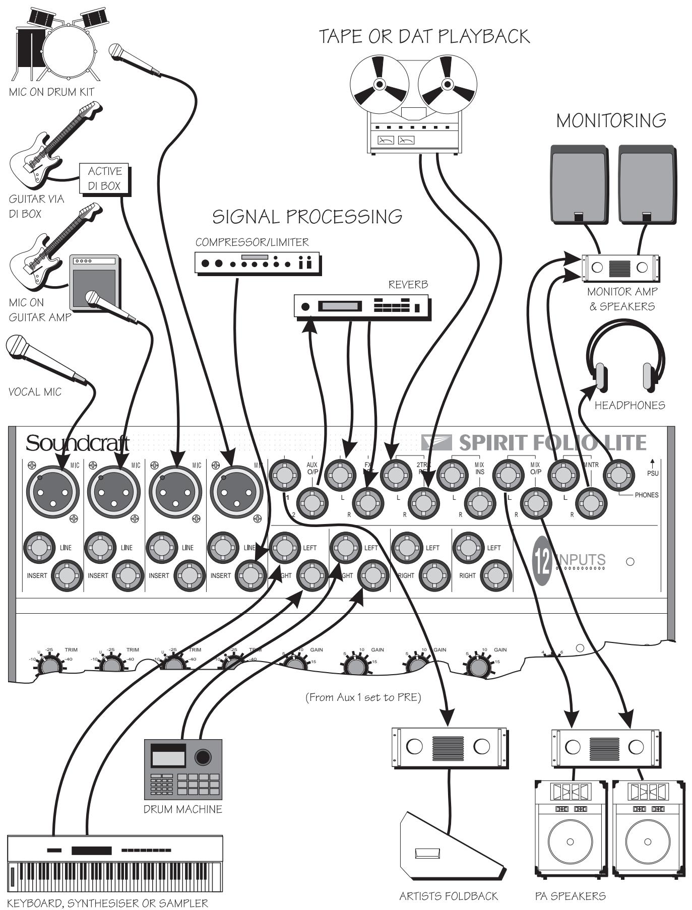
MIC LEVEL SOURCES
LINE LEVEL SOURCES
— LOUDSPEAKER OUTPUT —
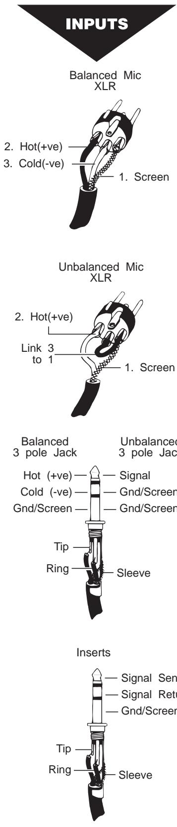
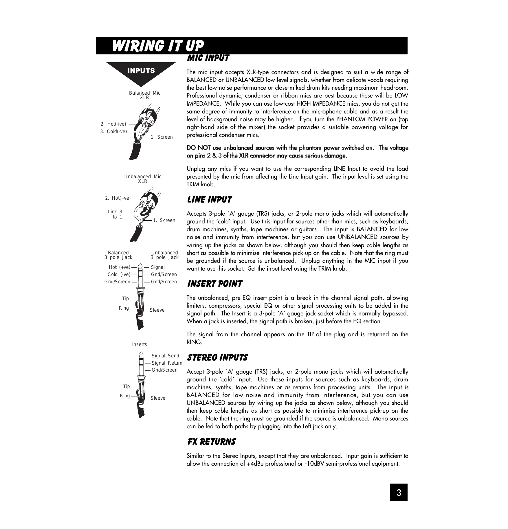
The mic input accepts XLR-type connectors and is designed to suit a wide range of BALANCED or UNBALANCED low-level signals, whether from delicate vocals requiring the best low-noise performance or close-miked drum kits needing maximum headroom. Professional dynamic, condenser or ribbon mics are best because these will be LOW IMPEDANCE. While you can use low-cost HIGH IMPEDANCE mics, you do not get the same degree of immunity to interference on the microphone cable and as a result the level of background noise may be higher. If you turn the PHANTOM POWER on (top right-hand side of the mixer) the socket provides a suitable powering voltage for professional condenser mics.
DO NOT use unbalanced sources with the phantom power switched on. The voltage on pins 2 & 3 of the XLR connector may cause serious damage.
Unplug any mics if you want to use the corresponding LINE Input to avoid the load presented by the mic from affecting the Line Input gain. The input level is set using the TRIM knob.
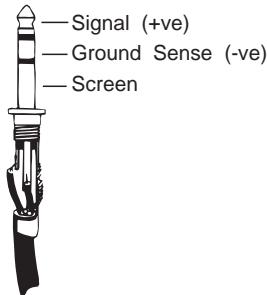
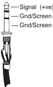
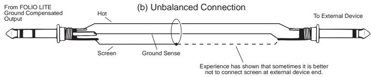
Accepts 3-pole 'A' gauge (TRS) jacks, or 2-pole mono jacks which will automatically ground the 'cold' input. Use this input for sources other than mics, such as keyboards, drum machines, synths, tape machines or guitars. The input is BALANCED for low noise and immunity from interference, but you can use UNBALANCED sources by wiring up the jacks as shown below, although you should then keep cable lengths as short as possible to minimise interference pick-up on the cable. Note that the ring must be grounded if the source is unbalanced. Unplug anything in the MIC input if you want to use this socket. Set the input level using the TRIM knob.
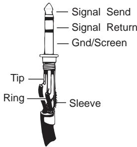
INSERT POINT
The unbalanced, pre-EQ insert point is a break in the channel signal path, allowing limiters, compressors, special EQ or other signal processing units to be added in the signal path. The Insert is a 3-pole 'A' gauge jack socket which is normally bypassed. When a jack is inserted, the signal path is broken, just before the EQ section.
The signal from the channel appears on the TIP of the plug and is returned on the RING.
Accept 3-pole 'A' gauge (TRS) jacks, or 2-pole mono jacks which will automatically ground the 'cold' input. Use these inputs for sources such as keyboards, drum machines, synths, tape machines or as returns from processing units. The input is BALANCED for low noise and immunity from interference, but you can use UNBALANCED sources by wiring up the jacks as shown below, although you should then keep cable lengths as short as possible to minimise interference pick-up on the cable. Note that the ring must be grounded if the source is unbalanced. Mono sources can be fed to both paths by plugging into the Left jack only.
FX RETURNS
Similar to the Stereo Inputs, except that they are unbalanced. Input gain is sufficient to allow the connection of +4dB professional or -10dBV semi-professional equipment.
OUTPUTS
Mix Inserts
Mix Outputs
Aux Outputs
Monitor Outputs
Headphones
MIX INSERTS
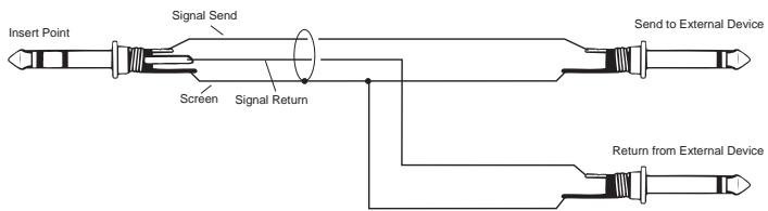
The unbalanced, pre-fade Mix insert point is a break in the output signal path to allow the connection of, for example, a compressor/limiter or graphic equaliser. The Insert is a 3-pole 'A' gauge jack socket which is normally bypassed. When a jack is inserted, the signal path is broken, just before the mix fader.
The mix signal appears on the TIP of the plug and is returned on the RING. A 'Y' lead may be required to connect to equipment with separate send and return jacks as shown below:
MIX OUTPUTS, AUX OUTPUTS
The Mix and Aux outputs are on 3-pole 'A' gauge jack sockets, wired as shown on the left and below, and incorporate ground compensation which helps to avoid ground loops and their associated hums and buzzes when feeding into unbalanced equipment.

MONITOR OUTPUTS
The Monitor outputs are unbalanced on 3-pole 'A' gauge jacks, wired as shown. The outputs are automatically cut off if a jack is inserted in the PHONES socket.
HEADPHONES
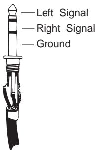
The PHONES output is a 3-pole 'A' gauge jack, wired as a stereo output as shown, suitable for headphones of 200 or greater, although impedances as low as 50 will operate satisfactorily. 8 headphones are not recommended. Inserting a jack automatically cuts off the Monitor outputs (see above), which are restored when the PHONES jack is removed. This allows a self-operator to continue monitoring while making voice recordings without having to turn the power amplifiers down.
GROUNDING CONSIDERATIONS
The power supply does not provide the mixer with any direct connection to mains ground, and therefore some care must be taken to ensure that a ground connection is made at an appropriate point in the system. In PA systems the most suitable point would be to ground through the Mix Outputs into the power amp leads. In a studio setup the Monitor Outputs would provide a suitable connection via the monitor power amp leads.
You will probably use your SPIRIT FOLIO LITE with a wide range of different types of sound source, and these will be at varying signal levels. The mic amp has been designed with a particularly wide gain range, but it is important to set the TRIM control correctly to give the best performance. If the input level is too high the signal will distort as it overloads the channel and causes clipping. If it is too low the level of any background hiss will be more noticeable and you may not be able to get enough signal level to the output of the mixer. This is illustrated in the diagram below.
Set up the individual mono input channels as follows:
Plug in the chosen source (usually the MIC input for mics and the LINE input for anything else). Plug in phantom powered mics before switching the phantom power on.
Set the rotary Mix Fader on the Master section fully anticlockwise. Press the PFL switch on the Master section to route PFL to the monitor and meters.
- Provide the chosen source with a typical signal level and press the PFL button by the fader. The level of signal will be shown on the Bargraph Meters.
- Adjust the input TRIM until the meter is just reaching the amber LED (0dB) at a typical maximum source level with a steady signal. If the source signal is rich in high-level transients (e.g. drums) a rather higher meter reading of +6/+9 will be needed to achieve an equivalent average level. This leaves enough headroom to cope with peaks in the signal without distortion.
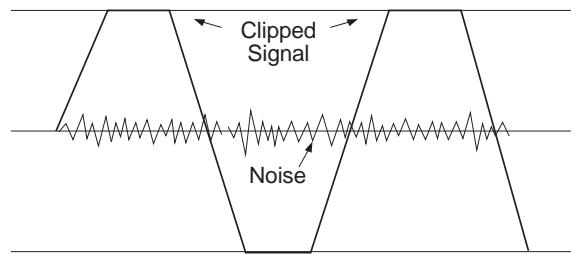
If the signal level is too high, clipping distortion may occur.
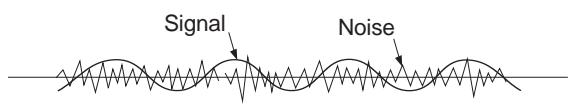
If the signal level is too low it may be masked by the noise.
Adjust each mono input channel in the same way.
If you find that you cannot set a reasonable level within the range of the TRIM control when using a MIC input, try the LINE input instead.
The Stereo inputs can be set up in a similar way. Start with the GAIN control anticlockwise, which will suit inputs from professional equipment with a +4dBu output. A higher GAIN setting will be needed for semiprofessional sources which typically have -10dBV output level.
You will now have initial settings for each of the input sources and are ready to start building a mix.
- Connect your power amplifiers and speakers and set the gain of the amplifiers to about 70% . Set the Master Fader fully clockwise, listening carefully for any hint of feedback or overload. You may find that the input fader settings will need to be edged back slightly as the mix is built up.
Listen carefully for the characteristic sound of 'feedback'. If you cannot achieve a satisfactory input level setting without feedback, adjust microphone and speaker positions and try again.
Careful microphone placement and the choice of a suitable type of microphone is essential for successful PA use. The aim should be to place the microphone as close as possible to the source, to cut out unwanted surrounding sounds. This allows a lower gain setting on the mixer and helps to avoid feedback. You will also find that a well-placed microphone will not need any appreciable equalisation.
The inherent low noise of the input channels on FOLIO LITE allows an alternative method of setting-up, which allows the use of the optimum range of the input faders.
Set the Master Fader fully clockwise.
Set all input faders to the '0' mark. Note that this still allows 10dB of gain in hand.
Gradually bring up each channel by adjusting the input TRIM control until the required mix is created.
SETTING UP FOR RECORDING
While the connections to the FOLIO LITE for PA work are quite straightforward, recording is rather more demanding because the mixer is not only required to mix down input signals but also to provide a monitor mix for artists to hear. The following describes a typical set-up for recording two tracks on a multitrack recorder, but would be similar for a 2-Track machine:
- Connect input sources and set gain as described opposite. Connect Mix Left & Right outputs to the multitrack tape inputs.
- Route the channel signal to the required tape input by setting the PAN fully left or right. For example, panning fully left will route the signal from the Left Mix output only. This allows an individual source to be sent to an individual tape track.
- Connect the multitrack tape outputs to the 2 Track Returns. Set the 2TRK LEVEL control fully clockwise for -10dBV sources, or at a lower setting for equipment with a higher output level.
- Connect a monitor amplifier for foldback headphones or a monitor speaker to the Aux 1 output. Set the amplifier volume to a normal listening level. Press the AUX 1 PRE switch on the Master section to set all channel Aux 1 sends to pre-fade.
Use the Aux 1 send controls on the input channels to set up a mono monitor mix. (make sure that all other Aux 1 controls are fully off)
If a compressor is to be used, connect this to the Mix Insert points.
- Connect any effects required using Aux 2, and return them to the mixer on unused Line or Stereo inputs or FX Return to allow the effect to be balanced with the original source.
If it is necessary to hear the off-tape signal as part of the foldback mix, for instance for overdubbing, connect the tape outputs to unused stereo or line inputs, which can access the Aux 1 send.
It is important to match the input and output levels of your mixer and recording device to avoid distortion and create the best recording.
- Set the recording level as recommended for your recording device, feeding a suitable signal from the Mix outputs. With MONITOR SOURCE selected to MIX the meters will display the signal being fed to the recorder.
Monitor the signal going to the recorder by selecting 2TRK on the MONITOR SOURCE switch. Gradually increase the 2TRK level while toggling the MONITOR SOURCE switch to alternate between the Mix output and 2TRK return until no change in level is audible or visible on the LED meters.
FOLIO LITE has 4 Mono input channels, each with balanced inputs for microphone and line level sources, and an Insert point to allow the signal to be taken out of the mixer, through an external piece of equipment and then back into the mixer to continue through to the final output. The Insert point comes before the EQ and allows limiters, compressors and other signal processing units to be added as required to particular channels.
TRIM
This knob sets how much of the source signal is sent to the rest of the mixer. Adjust it carefully -too high and the signal will overload and distort, too low, and the level of any background hiss will be more noticeable and you may not be able to get enough signal level to the output of the mixer.
The 'U' mark gives a nominal unity gain for the Line input.
EQUALISER
The Equaliser (EQ) gives fine control over the signal quality, particularly to improve the sound in live PA applications where the original signal is often far from ideal.
The EQ knobs can have a dramatic effect on the sound, so use them sparingly and listen carefully to the result.
HF EQ
Turn to the right to boost high (treble) frequencies by up to 15dB at 12kHz , adding crispness to cymbals, vocals and electronic instruments. Turn to the left to cut these frequencies, reducing hiss or distorted consonants which can occur with certain types of microphone. Set the knob in the centre-detented position when not required.
LFEQ
Turn to the right to boost low (bass) frequencies by up to 15dB at 60Hz , adding warmth to vocals or extra punch to synths, guitars and drums. Turn to the left to reduce hum, stage rumble or improve a mushy sound. Set the knob to the centre-detented position when not required.
AUX SEND1
This is used to set up a separate mix for FOLDBACK, EFFECTS or recording, and the combination of all the Aux 1 Sends is mixed to the Aux 1 Output. For Effects it is useful for this to fade up and down with the FADER (this is called POST-FADE), but for Foldback or Monitor feeds it is important for the send to be independent of the FADER (this is called PRE-FADE). The Master Section AUX1 PRE switch allows you to chose pre- or post-fade as required. Leave the knob turned down when not in use.
PAN
This control sets the amount of the channel signal feeding the Right and Left MIX outputs, allowing you to move the source smoothly across the stereo image. When the control is turned fully right or left the signal is sent only to that side of the mix.
AUX SEND 2
This is similar to the Aux Send 1 control, but is always POST-FADE.
FADER
The rotary FADER gives you smooth control of the overall signal level in the channel strip, allowing precise balancing of the various source signals being mixed to the Master Section.
PFL
When the PFL (Pre-Fade-Listen) switch is pressed the pre-fade signal is fed to both sides of the Monitor. It may be heard on headphones or the monitor output and shown on the meters if the Master section PFL switch is pressed.
You use this switch to listen to a channel signal without affecting the mixer outputs, to check the signal quality, set the input TRIM, or simply to check that it is there!
FOLIO LITE has 4 Stereo input channels, suitable for a wide variety of line level sources, such as keyboards, drum machines, synths or tape machines. The inputs are balanced for low noise and immunity from interference, but you can use unbalanced sources (see 'Connections' for wiring details), although you should then keep cable lengths as short as possible to minimise interference pick-up.
GAIN
This knob allows you to match the input level to suit a wide variety of professional, semi-professional and hi-fi sources.
Start with a low setting, especially for professional equipment, and increase it if you cannot reach an adequate signal level with the fader at maximum.
EQUALISER
The Equaliser (EQ) gives fine control over the signal quality, to minimise background noise, or to alter the character of synthesised voices from electronic instruments.
The EQ knobs can have a dramatic effect on the sound, so use them sparingly and listen carefully to the result.
HFEQ
Turn to the right to boost high (treble) frequencies by up to 15dB at 12kHz , adding crispness to percussion from drum machines, synths and electronic instruments. Turn to the left to cut these frequencies, reducing hiss or excessive Brillinace. Set the knob in the centre-detented position when not required.
LFEQ
Turn to the right to boost low (bass) frequencies by up to 15dB at 60Hz , adding extra punch to synth, guitars and drums. Turn to the left to reduce hum, boominess or improve a mushy sound. Set the knob to the centre-detented position when not required.
AUX SEND1
This is used to set up a separate mono mix for FOLDBACK or to drive EFFECTS processors, and the combination of all the Aux 1 Sends is mixed to the Aux 1 Output. For Effects it is useful for this to fade up and down with the FADER (this is called POST-FADE), but for Foldback or Monitor feeds it is important for the send to be independent of the FADER (this is called PRE-FADE). The Master Section AUX1 PRE switch allows you to chose pre- or post-fade as required. Leave the knob turned down when not in use.
BALANCE
This control sets the amount of the channel signal feeding the Right and Left MIX outputs, allowing you to balance the source in the stereo image. When the control is turned fully right or left you feed only that side of the signal to the mix.
AUX SEND 2
This is similar to the Aux Send 1 control, but is always POST-FADE.
FADER
The rotary FADER gives you smooth control of the overall signal level in the channel strip, allowing precise balancing of the various source signals being mixed to the Master Section.
PFL
When the PFL (Pre-Fade-Listen) switch is pressed the pre-fade channel signal is fed in stereo to the Monitor. It may be heard on headphones or the monitor output and shown on the meters if the Master section PFL switch is pressed.
You use this switch to listen to a channel signal without affecting the mixer outputs, to check the signal quality, set the input TRIM, or simply to check that it is there!
FX RETURN
The unbalanced FX Returns are an ideal place to connect the output of an EFFECTS unit, without using up any of the LINE inputs.
The control sets the level of signal fed directly to the MIX. When set fully clockwise the inputs will be matched to -10dBV (semi-professional) sources, or will suit +4dBu sources with the control at a lower setting.
A mono source, plugged into the LEFT jack only is fed to both sides of the MIX.
2TRK(2 TRACK)
The unbalanced 2TK returns are an ideal place to connect the playback of a tape machine, without using up any of the LINE inputs.
The control sets the level of signal fed directly to the MIX. When set fully clockwise the inputs will be matched to -10dBV (semi-professional) sources, or will suit +4dBu sources with the control at a lower setting.
A mono source, plugged into the LEFT jack only is fed to both sides of the MIX.
PHANTOM 48V
This switch turns on the 48V PHANTOM POWER to the mic inputs, sending a powering voltage down the same wires as the signal to suit many professional condenser mics.
DO NOT turn on the phantom power when using unbalanced mics which may be damaged by the voltage.
Note: Mics should always be plugged in before switching the Phantom Power ON.
AUX 1 PRE
Press this switch to make all of the AUX 1 sends on the input channels PRE-FADE. This means that they will all be unaffected by channel fader position, making them ideal for FOLDBACK or MONITORING.
When the switch is released the AUX 1 sends are all POST-FADE, and will fade up and down with the channel faders.
BARGRAPH METERS
The three-colour, peak-reading BARGRAPH METERS show the level of the selected monitor source (MIX, 2TRK or PFL) to give a warning of excessive peaks in the signal which might cause overloading.
With the Master Fader at OdB, aim to keep the signal just touching the amber segments, with a steady signal, or up to +6 / + 9 on peaky signal sources such as drum beats.
2TRK TO MIX
Press this switch to route the 2TK Return signal to the MIX outputs giving you two extra inputs at mixdown. Adjust the level with the 2TRK control. Overall level will be set by the MIX FADER. DO NOT PRESS THIS SWITCH WHEN RECORDING or load feedback will occur and ruin the recording.
MONITOR SOURCE
This switch selects the source for the Monitor outputs or Headphones. When released the source is the MIX, when pressed it becomes the 2 Track Return signal. Note that the selected source is replaced by PFL if the the PFL switch is pressed.
MIX FADER
The MIX FADER sets the final level of the MIX outputs. The fader should normally be set close to the '0dB' mark if the input levels have been set correctly.
MONITOR
This control sets the output level to the MONITOR LEFT & RIGHT outputs.
If HEADPHONES are plugged into the PHONES jack the monitor outputs are cut off, and the knob then sets the headphone level.
PFL
Pressing this switch replaces the selected monitor source with the stereo PFL signal (mono from mono input channels).
Releasing the switch returns the monitor to the previously selected source.
TYPICAL SPECIFICATIONS
MIX NOISE Input faders down, Master Faders up < -81dBu
AUX NOISE Input Sends down < -88dBu
E.I.N. Source resistance 150, -128dBu
DISTORTION Mic Gain 30dB, Mix Out at +14dBu <0.007% @ 1kHz
CROSSTALK (measured at 1kHz sine wave)
Input Fader Attenuation >85dB
Aux Send Attenuation >84dB
Adjacent Channel >90dB
Stereo Separation >75dB
FREQUENCY RESPONSE 20Hz-30kHz, relative to 1kHz +/- 1dB
C.M.R.R. Mono Input at max. gain, measured @ 1kHz 85dB Stereo Input at any gain 50dB
Mic Inputs 2kΩ Line Inputs 10kΩ Outputs 75Ω
INPUT & OUTPUT LEVELS Mic Input max. level +16dBu Line Input max. level > + 30dB u Any Output max. level +21dB u Headphone Output each side 130mW into 600Ω
WEIGHT Console Power Pack 2.5Kg 0.6Kg
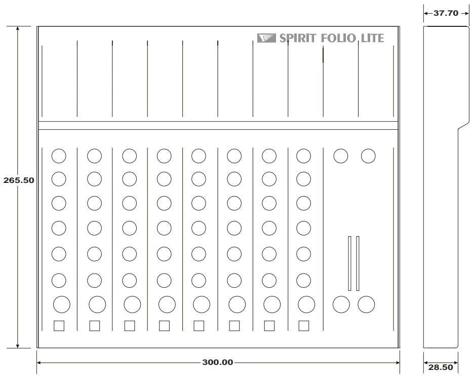
DIMENSIONS
All dimensions are in millimetres
| AFL (After Fade Listen) | a function that allows the operator to monitor the post-fade signal in a channel independently of the main mix. |
| Balance | the relative levels of the left and right channels of a stereo signal. |
| Balanced | a method of audio connection which ‘balances’ the signal between two wires and a screen which carries no signal. Any interference is picked up equally by the two wires, but out of phase resulting in cancellation of the interference signal. |
| Clipping | the onset of severe distortion in the signal path, usually caused by the peak signal voltage being limited by the circuit's power supply voltage. |
| dB (decibel) | a ratio of two voltages or signal levels, expressed by the equation dB=20Log<M>10 (V1/V2). Adding the suffix ‘u’ denotes the ratio is relative to 0.775V RMS. |
| DI | (direct injection) the practice of connecting an electric musical instrument directly to the input of the mixing console, rather than to an amplifier and loudspeaker which is covered by a microphone feeding the console. |
| Effects | the use of devices to alter or process the sound to add special effects e.g. reverb, normally as a mix of the original (‘dry’) sound and the treated version. |
| Equaliser | a device that allows the boosting or cutting of selected bands of frequencies in the signal path. |
| Feedback | the ‘howling’ sound caused by bringing a microphone too close to a loudspeaker driven from its amplified signal. |
| Foldback | a feed sent back to the artistes via loudspeakers or headphones to enable them to monitor the sounds they are producing. |
| Frequency response | the variation in gain of a device with frequency. |
| Ground Compensation | a technique used on unbalanced outputs to cancel out the effect of ground loops caused by connections to external equipment. |
| Headroom | the available signal range above the nominal level before clipping occurs. |
| Line level signals | at a nominal level of -10 to +6dBu, usually coming from a low impedance source. |
| Peaking | an equaliser response curve affecting only a band of frequencies i.e. based on a bandpass response. |
| PFL (pre-fade listen) | a function that allows the operator to monitor the pre-fade signal in a channel independently of the main mix. |
| Phantom Power | the +48V d.c. voltage applied equally to the two signal pins of a balanced mic input to provide powering for condenser microphones. |
| Post-Fade | the point in the signal path after the channel or master fader and therefore affected by fader position. |
| Processor | a device which affects the whole of the signal passing through it, e.g. gate, compressor or equaliser |
| Rolloff | a fall in gain at the extremes of the frequency response. |
| Signal to Noise Ratio | a expression of the difference in level between the audio signal and background system noise. |
| Solo-in-Place | a function that allows the operator to listen to a selected channel on its own but complete with all relevant effects, by automatically muting all other inputs. |
| Talkback | the operator speaking to the artistes or to tape via the auxiliary or group outputs. |
| Tape Return | a line level input provided specifically to receive the playback output of a tape machine |
| Transient | a momentary rise in the signal level. |
| TRS Jacks | a 3-pole jack with Tip, Ring and Sleeve connections |
| Unbalanced | a method of audio connection which uses a single signal wire and the cable screen as the signal return. This method does not provide the noise immunity of a balanced input (see above). |
USCITE MIX, USCITE AUX
ESPNOL - INTRODUCTION