
SPIRIT F1 - Mixer SOUNDCRAFT - Free user manual and instructions
Find the device manual for free SPIRIT F1 SOUNDCRAFT in PDF.


User questions about SPIRIT F1 SOUNDCRAFT
0 question about this device. Answer the ones you know or ask your own.
Ask a new question about this device
Download the instructions for your Mixer in PDF format for free! Find your manual SPIRIT F1 - SOUNDCRAFT and take your electronic device back in hand. On this page are published all the documents necessary for the use of your device. SPIRIT F1 by SOUNDCRAFT.
USER MANUAL SPIRIT F1 SOUNDCRAFT
Safety Precautions 3
Please read this manual carefully before connecting your Mixer and Power Supply Unit for the first time.
Safety Symbol Guide
For your own safety and to avoid invalidation of the warranty all text marked with these Symbols should be read carefully.

CAUTIONS
Must be followed carefully to avoid bodily injury.

WARNING
Must be observed to avoid damage to your equipment.

NOTES
Contain important information and useful tips on the operation of your equipment.
© Harman International
Industries Ltd. 2001
All rights reserved
Parts of the design of these products may be protected by worldwide patents
Part No. ZM0210
Issue: 2
Soundcraft is a trading division of Harman International Industries Ltd. Information in this manual is subject to change without notice and does not represent a commitment on the part of the vendor.
Soundcraft shall not be liable for any loss or damage whatsoever arising from the use of information or any error contained in this manual.
No part of this manual may be reproduced, stored in a retrieval system, or transmitted, in any form or by any means, electronic, electrical, mechanical, optical, chemical, including photocopying and recording, for any purpose without the express written permission of Soundcraft.

Harman International Industries Limited
Cranborne House
Cranborne Road
POTTERS BAR
Hertfordshire
EN63JN
UK
E-MAIL: info@soundcraft.com
Tel:+44 (0)1707 665000
fax:+44 (0)1707 660742
http://www.soundcraft.com
Warranty
1 Soundcraft is a trading division of Harman International Industries Ltd. End User means the person who first puts the equipment into regular operation.
Dealer means the person other than Soundcraft (if any) from whom the End User purchased the Equipment, provided such a person is authorised for this purpose by Soundcraft or its accredited Distributor.
Equipment means the equipment supplied with this manual.
2 If within the period of twelve months from the date of delivery of the Equipment to the End User it shall prove defective by reason only of faulty materials and/or workmanship to such an extent that the effectiveness and/or usability thereof is materially affected the Equipment or the defective component should be returned to the Dealer or to Soundcraft and subject to the following conditions the Dealer or Soundcraft will repair or replace the defective components. Any components replaced will become the property of Soundcraft.
3 Any Equipment or component returned will be at the risk of the End User whilst in transit (both to and from the Dealer or Soundcraft) and postage must be prepaid.
4 This warranty shall only be valid if:
a) the Equipment has been properly installed in accordance with instructions contained in Soundcraft's manual; and
b) the End User has notified Soundcraft or the Dealer within 14 days of the defect appearing; and
c) no persons other than authorised representatives of Soundcraft or the Dealer have effected any replacement of parts maintenance adjustments or repairs to the Equipment; and
d) the End User has used the Equipment only for such purposes as Soundcraft recommends, with only such operating supplies as meet Soundcraft's specifications and otherwise in all respects in accordance Soundcraft's recommendations.
5 Defects arising as a result of the following are not covered by this Warranty: faulty or negligent handling, chemical or electro-chemical or electrical influences, accidental damage, Acts of God, neglect, deficiency in electrical power, air-conditioning or humidity control.
6 The benefit of this Warranty may not be assigned by the End User.
7 End Users who are consumers should note their rights under this Warranty are in addition to and do not affect any other rights to which they may be entitled against the seller of the Equipment.
SAFETY PRECAUTIONS
The SPIRIT FI mixer must only be connected through the Power Supply supplied.
The wires in the mains lead are coloured in accordance with the following code:
Neutral: Blue
(White - US)
Live: Brown
(Black - US)
As the colours of the wires in the mains lead may not correspond with the coloured markings identifying the terminals in your plug, proceed as follows:
- The wire which is coloured Blue must be connected to the terminal in the plug which is marked with the letter N.
- The wire which is coloured Brown must be connected to the terminal in the plug which is marked with the letter L.
Ensure that these colour codings are followed carefully in the event of the plug being changed.
To avoid the risk of fire, replace the mains fuse only with the correct value fuse, as indicated on the power supply.

CAUTIONS
- Do not install near any heat sources such as radiators, heat resistors, stoves, or other apparatus (including amplifiers) that produce heat.
- Do not use this apparatus near water.
- Protect the power cord from being walked on or pinched particularly at plugs, convenience receptacles and the point where they exit from the apparatus.
- Only use cables and hardware specified by the manufacturer.
- Unplug this apparatus during lightning storms or when unused for long periods of time.
Refer all servicing to qualified service personnel. - It is recommended that all maintenance and service on the product should be carried out by Soundcraft or its authorised agents. Soundcraft cannot accept any liability whatsoever for any loss or damage caused by service, maintenance or repair by unauthorised personnel.
- If a trolley is used, use caution when moving the trolley / apparatus combination to avoid injury from tip-over.

WARNING
- Read these instructions.
- Keep these instructions.
Heed all warnings. - Follow all instructions.
- This unit contains no user serviceable parts. Refer all servicing to a qualified service engineer, through the appropriate Soundcraft dealer.
- Clean only with a damp cloth.
- DO Install in accordance with the manufacturers instructions.
SICHERHEITSHINWEISE
The mic input accepts XLR-type connectors and is designed to suit a wide range of BALANCED or UNBALANCED signals. Professional dynamic, condenser or ribbon mics are best because these will be LOW IMPEDANCE. You can use low-cost HIGH IMPEDANCE mics, but the level of background noise will be higher. If you press the 48V switch down (top right-hand side of the mixer) the socket provides a suitable powering voltage for professional condenser mics (this is also known as Phantom Power).
ONLY connect condenser microphones with the 48V powering OFF (switch UP), and ONLY turn the 48V powering on or off with all output faders DOWN, to prevent damage to the mixer or external devices.
TAKE CARE when using unbalanced sources, which may be damaged by the phantom power voltage on pins 2 & 3 of the XLR connector.
Unplug any mics if you want to use the LINE Input. The input level is set using the SENS knob.
2 LINE INPUT
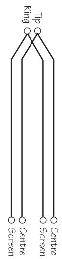
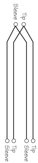
Accepts 3-pole 'A' gauge (TRS) jacks. Use this high impedance input for sources other than mics, such as keyboards, drum machines, synths, tape machines or guitars. The input is BALANCED for low noise and top quality from professional equipment, but you can use UNBALANCED sources by wiring up the jacks as shown, although you should then keep cable lengths as short as possible. Unplug anything in the MIC input if you want to use this socket. Set the input level using the SENS knob.
3 INSERT POINT
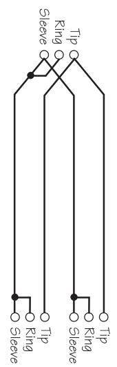
The unbalanced, pre-EQ insert point is a break in the channel signal path, allowing limiters, compressors, special EQ or other signal processing units to be added in the signal path. The Insert is a 3-pole 'A' gauge jack socket which is normally bypassed. When a jack is inserted, the signal path is broken, just before the EQ section. The Send may be tapped off as an alternative pre-fade, pre-EQ direct output if required, using a lead with tip and ring shorted together so that the signal path is not interrupted (see left).
4 SENS (Sensitivity)
This knob sets how much of the source signal is sent to the rest of the mixer. Too high, and the signal will distort as it overloads the channel. Too low, and the level of any background hiss will be more noticeable and you may not be able to get enough signal level to the output of the mixer.
Setting the knob to the 'U' mark gives unity gain for the LINE input. Note that some sound equipment, particularly that intended for domestic use, operates at a lower level (-10dBV) than professional equipment and will therefore need a higher gain setting to give the same output level.
See 'Setting Up & Troubleshooting' on page 20 to learn how to set SENS correctly.
ANSCHLUSSE
MONO EINGANG
Pressing this switch activates a steep 18dB per octave filter which reduces the level of bass frequencies only, and is a real bonus for a such a small mixer. Use this in live PA situations to clean up the mix, reducing stage rumble or 'popping' from microphones.
6 EQUALISER
The Equaliser (EQ) allows fine manipulation of the frequency bands, and is particularly useful for improving the sound in live PA applications where the original signal is often far from ideal and where slight boosting or cutting of particular voice frequencies can really make a difference to clarity. The EQ knobs can have a dramatic effect, so use them sparingly and listen carefully as you change any settings so that you get to know how they affect the sound.
HF EQ
Turn clockwise to boost high (treble) frequencies (12kHz and above) by up to 15dB, adding crispness to cymbals, vocals and electronic instruments. Turn anticlockwise to cut by up to 15dB, reducing hiss or excessive sibilance which can occur with certain types of microphone. Set the knob in the centre-detented position when not required.
MID EQ
There are two knobs which work together to form a SWEPT MID EQ. The lower knob provides 15dB of boost and cut, just like the HF EQ knob, but the frequency at which this occurs can be set by the upper knob over a range of 240Hz to 6kHz . This allows some truly creative improvement of the signal in live situations, because this mid band covers the range of most vocals. Listen carefully as you use these controls together to find how particular characteristics of, for instance, a vocal signal can be enhanced or reduced. Set the gain (lower) knob to the centre-detented position when not required. Note: Q is set at 1.5.
LF EQ
Turn clockwise to boost low (bass) frequencies (60Hz and below) by up to 15dB, adding warmth to vocals or extra punch to synths, guitars and drums. Turn anticlockwise to cut low frequencies by up to 15dB for reducing hum, stage rumble or to improve a mushy sound. Set the knob to the centredetented position when not required.
7 AUX SENDS
These are used to set up a separate mixes for FOLDBACK, EFFECTS or recording, and the combination of each Aux Send is mixed to the respective Aux Output at the rear of the mixer. For Effects it is useful for the signal to fade up and down with the fader (this is called POST-FADE), but for Foldback or Monitor feeds it is important for the send to be independent of the fader (this is called PRE-FADE). All Aux Sends are muted with the other channel outputs when the ON switch is released.
AUX SEND 1
This is always PRE-FADE, POST-EQ and therefore most appropriate for foldback or monitor mixes or external submix.
This is normally POST-FADE, POST-EQ and would typically be used as an effects send, but may be switched globally to PRE-FADE, POST-EQ using the POST/PRE switch on the Master section, providing a second foldback or monitor send if required.
AUX SEND 3
This is always POST-FADE, POST-EQ for use as effects sends, external submix (or for a Centre Voice speaker cluster or mono Tape mix).
8 PAN
This control sets the amount of the channel signal feeding the Left and Right MIX buses, allowing you to move the source smoothly across the stereo image. When the control is turned fully right or left you are able to route the signal at unity gain to either left or right outputs individually.
9 ON
All outputs from the channel except inserts are muted when the ON switch is released and enabled when the switch is down, allowing levels to be preset before the signal is required.
10 FADER
The 100mm FADER, with a custom-designed law to give even smoother control of the overall signal level in the channel strip, allows precise balancing of the various source signals being mixed to the Master Section. You get most control when the input SENSITIVITY is set up correctly, giving full travel on the fader. See the `Setting Up & Troubleshooting' section on page 20 for help in setting a suitable signal level.
11 PFL
When the latching PFL switch is pressed, the pre-fade, post-EQ signal is fed to the headphones, control room output and meters, where it replaces the selected monitor source (MIX or 2TK). The PFL/AFL LED on the Master section illuminates to warn that a PFL is active. This is a useful way of listening to any required input signal without interrupting the main mix, for making adjustments or tracing problems.
Each stereo input channel comprises two pairs of inputs per channel strip:
UNBALANCED INPUTS (Upper)
These high impedance inputs are unbalanced on RCA phono connectors, and are intended for use with CD players, DAT machines or Hi-Fi equipment. Alternatively they may be used as simple effects returns or stereo instrument inputs.
LEVEL (Unbalanced inputs)
The LEVEL control sets the level of the channel signal to Mix.
3 BALANCED INPUTS (Lower)
These high impedance inputs accept 3-pole 'A' gauge (TRS) jacks. Use these inputs for sources such as keyboards, drum machines, synths, tape machines or processing units. The inputs are BALANCED for low noise and top quality from professional equipment, but you can use UNBALANCED sources by wiring up the jacks as shown in the "Connecting Leads" section on page 28 in this manual, although you should then keep cable lengths as short as possible. Mono sources may be used by plugging into the left jack only.
4 GAIN (Balanced inputs)
The GAIN control sets the input level to the channel, allowing matching to a wide range of line level sources.
5 EQUALISER
HF EQ
Turn clockwise to boost high (treble) frequencies, adding crispness to percussion from drum machines, synths and electronic instruments. Turn anticlockwise to cut these frequencies, reducing hiss or excessive brilliance. Set the knob in the centre-detented position when not required. The control has a shelving response giving 15dB of boost or cut at 12kHz and above.
LF EQ
Turn clockwise to boost low (bass) frequencies, adding extra punch to synths, guitars and drums. Turn anticlockwise to reduce hum, boominess or improve a mushy sound. Set the knob to the centre-detented position when not required. The control has a shelving response giving 15dB of boost or cut at 60Hz and below.
6 AUX SENDS
These are used to set up a separate mixes for FOLDBACK, EFFECTS or recording, and the combination of each Aux Send is mixed to the respective Aux Output at the rear of the mixer. For Effects it is useful for the signal to fade up and down with the fader (this is called POST-FADE), but for Foldback or Monitor feeds it is important for the send to be independent of the fader (this is called PRE-FADE). The Aux Sends are muted with the other channel outputs when the ON switch is released.
AUX SEND 1
This is always PRE-FADE, POST-EQ and therefore most appropriate for foldback or monitor mixes.
STEREO EINGANG
This is normally POST-FADE, POST-EQ and would typically be used as an effects send, but may be switched globally to PRE-FADE, POST-EQ using the POST/PRE switch on the Master section, providing a second foldback or monitor send if required.
AUX SEND 3
This is always POST-FADE, POST-EQ.
7 BALANCE
This control sets the amount of the channel signal feeding the Left and Right MIX buses, allowing you to balance the source in the stereo image. When the control is turned fully right or left you feed only that side of the signal to the mix. Unity gain is provided by the control in the centre-detented position.
8 ON
All outputs from the channel except inserts are muted when the ON switch is released and enabled when the switch is down.
9 FADER
The 100mm FADER gives you smooth control of the overall signal level in the channel strip, allowing precise balancing of the various source signals being mixed to the Master Section. It is important that the input level is set correctly to give maximum travel on the fader which should normally be used at around the '0' mark. See the `Setting Up & Troubleshooting' section on page 20 for help in setting the right level.
10 PFL
When the latching PFL switch is pressed, the pre-fade, post-EQ signal is fed in mono to the headphones, control room output and meters, where it replaces the selected monitor source (MIX or 2TK). The PFL/AFL LED on the Master section illuminates to warn that a PFL is active. The Left and Right meters display the PFL signal in mono. This is a useful way of listening to any required input signal without interrupting the main mix, for making adjustments or tracing problems.
AUX 1
Many professional condenser mics need an external powering voltage, normally 48V, also known as PHANTOM POWER. This is a method of sending a powering voltage down the same wires as the mic signal. Press the switch to supply the 48V power to all of the MIC inputs. The adjacent LED illuminates when the power is active.
DO NOT USE unbalanced mics with 48V switched on as they may be damaged by the phantom power voltage. Balanced dynamic mics can normally be used with 48V switched on (contact your microphone manufacturer for guidance)
Mics should always be plugged in, and all output faders set to minimum before switching 48V ON to avoid damage to external equipment
2 POWER INDICATOR
This LED lights to show when power is connected to the console.
3 BARGRAPH METERS
The 3-colour peak reading BARGRAPH METERS normally follow the Monitor selection to show either the level of the MIX RIGHT and MIX LEFT outputs or the 2TK input if the MIX/2TK switch (6) is pressed, giving you a constant warning of excessive peaks in the signal which might cause overloading. Aim to keep the signal within the amber segments at peak levels for best performance.
Similarly, if the output level is too low and hardly registering at all on the meters, the level of background noise may become significant. Take care to set up the input levels for best performance.
When any PFL or AFL switch is pressed, the meters switch to show the selected PFL/AFL signal on both meters, in mono.
4 MONO SUM
The Mix Left and Right signals are summed to an impedance balanced MONO output on a 3 pole 'A' gauge jack. Output level is set by the dedicated rotary control. Monitoring of the Mono output can, if required, be done at the external equipment it feeds, or when the signal is brought back to a spare console input.
5 MONITOR + PHONES LEVEL
This control sets the output level to the MONITOR LEFT & RIGHT outputs. If HEADPHONES are plugged into the PHONES jack the Monitor outputs are cut off, and the knob then sets the headphone listening level. When the PHONES are unplugged the Monitor output is restored.
When any PFL or AFL switch is pressed the source for the Monitor outputs and Headphones is switched to the mono PFL/AFL signal without interrupting the other outputs from the mixer, to allow individual signals to be monitored. The PFL/AFL LED illuminates to show that PFL/AFL is the source for the monitors and meters. The original monitor source is restored when the PFL/AFL switches are released.
MASTER SEKTION
1 48V
Pressing the 2TK switch selects the 2TK input as the monitor source, instead of the MIX.
7 2TK LEVEL
The rotary control sets the level of the 2 Track Tape input, which is routed to the headphones, monitor outputs and meters. These unbalanced inputs, on RCA phono connectors, are ideal to connect the playback of a tape machine for monitoring.
8 2TK TO MIX
Press this switch to add the 2TK signal to the stereo Mix, at a level set by the 2TK LEVEL control (7). The signal is added pre-insert, pre-fader, and is an ideal way of feeding pre-show music to the mix in live applications, or could be used as an alternative effects return or line level input if required.
9 AUX MASTERS
Each of the three Aux outputs has a master output level control and associated AFL switch.
AUX AFLs
Just like the PFL switches on the channels, you can monitor each AUX output by pressing the AFL switch. This routes the AUX output signal to the MONITOR or PHONES, replacing any existing signal (normally the Monitor receives either MIX, SUB or 2TK, see above). The METERS also switch from the selected source to display the PFL/AFL signal and the PFL/AFL LED lights to warn that a PFL or AFL switch is pressed. When you release the switch the Monitor swaps back to the previous source.
AUX 2 POST/PRE
The input channels provide both Pre- and Post-Fade AUX 2 sends which may be selected desk-wide on the Master Section. Press the POST/PRE switch to make all of the AUX 2 Sends on the channel strips PRE-FADE, POST-EQ. This means that they will all be unaffected by the position of the channel faders, making them ideal for FOLDBACK or MONITORING.
When the switch is released the AUX 2 Sends are all POST-FADE, POST-EQ and will fade up and down with the channel faders. This is more suitable for effects sends which need to fade out with the associated source.
10 MASTER FADERS
The MASTER FADERS set the final level of the Left and Right MIX outputs. These should normally be set close to the '0' mark if the input GAIN settings have been correctly set, to give maximum travel on the faders for smoothest control.
6 2TK
Once you have connected up your system (see the sections on connection and wiring earlier in this manual for guidance) you are ready to set initial positions for the controls on your mixer.
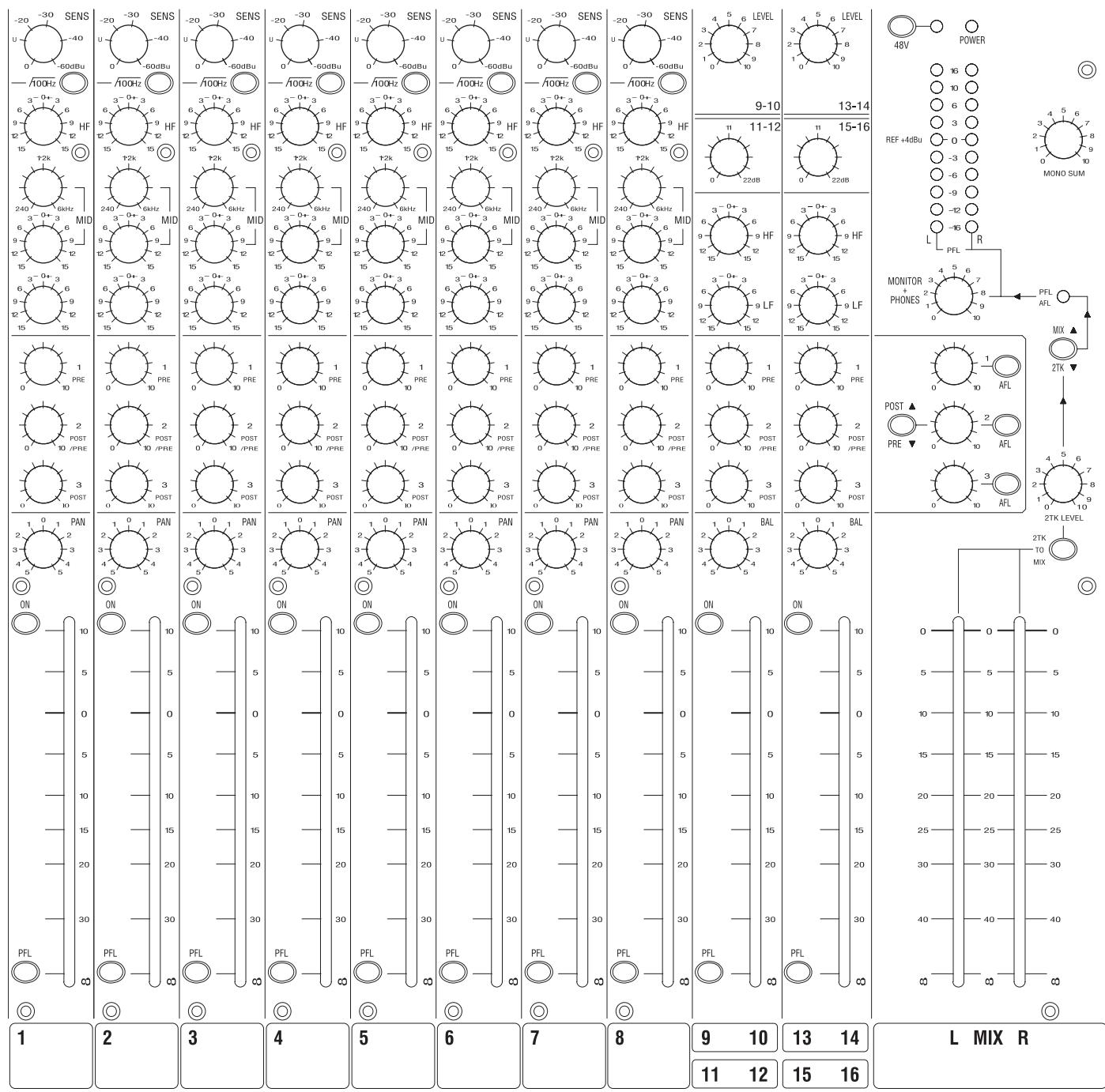
The front panel drawing inside the rear cover shows typical initial control positions which may serve as a useful guide to setting up the mixer for the first time.
Set up individual input channel as follows:
- Connect your sources (microphone, keyboard etc.) to the required inputs and press the ON switches. Note: Phantom powered mics should be connected before the 48V is switched on.
- Set Master faders at 0, input faders at 0, and set power amplifier levels to about 70% .
-
Provide a typical performance level signal and press the PFL button on the first channel, monitoring the level on the bargraph meters.
-
Adjust the input gain until the meter display is in the amber section, with occasional peaks to the first red LED at a typical maximum source level. This allows sufficient headroom to accommodate peaks and establishes the maximum level for normal operation (but see note below).
- Repeat this procedure on other channels as required. As more channels are added to the mix, the meters may move into the red section. Adjust the overall level using the Master Faders if necessary.
- Listen carefully for the characteristic sound of `feedback'. If you cannot achieve satisfactory input level setting without feedback, check microphone and speaker placement and repeat the exercise. If feedback persists, it may be necessary to use a Graphic Equaliser to reduce the system response at particular resonant frequencies.
Note: The initial settings should only be regarded as a starting point for your mix. It is important to remember that many factors affect the sound during a live performance, for instance the channel EQ settings or even the size of the audience!
You are now ready to start building the mix and this should be done progressively, listening carefully for each component in the mix and watching the meters for any hint of overload. If this occurs, back off the appropriate Channel Fader slightly until the level is out of the red segments, or adjust the Master Faders.
Troubleshooting
No Power
Is the mains supply present? Check the mains outlet with another device.
Is the power lead firmly connected?
- If appropriate, is the PortaPower unit connected correctly?
Condenser Mic Not Working
Is the 48V turned on?
Is the mic plugged into the Mic input?
Is the mic cable a balanced 3-wire type?
Meters not showing any signal
Has the input gain been set correctly (see above)?
Is the source connected to the appropriate input socket for the level of signal?
- Are the Mix faders set at max., and are input faders set high enough?
- Are the relevant channels turned ON?
- If monitoring 2TK, is the Master Mix/2TK switch pressed to select the 2TK input?
Is there a PFL/AFL pressed on another channel?
No Monitor output
Is a headphone jack plugged in?
Is the Monitor ^+ Phones control set high enough?
Headphones Distorting
- Are the headphones greater than 200 impedance?
Is the Monitor ^+ Phones level set too high?
Connecting 2 Folio F1s

2-pole 14" (A guage TS)ack

RCA phono
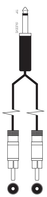
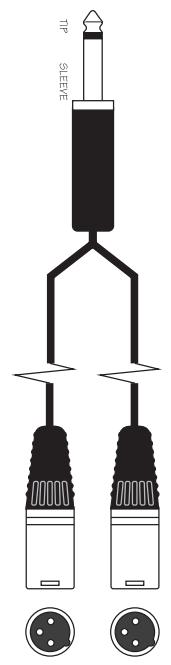
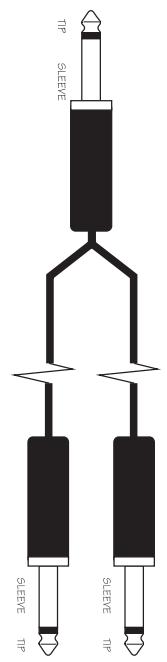
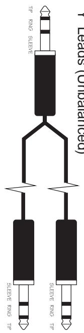
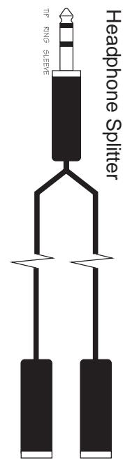
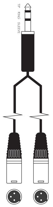
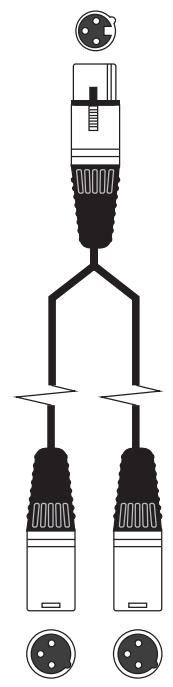
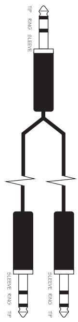
(poeuee) speeT,人
e 1nndn no x!W 'xN'...pOsn 2nM

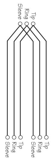
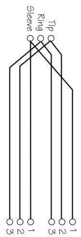
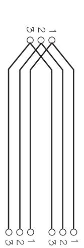
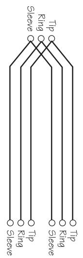
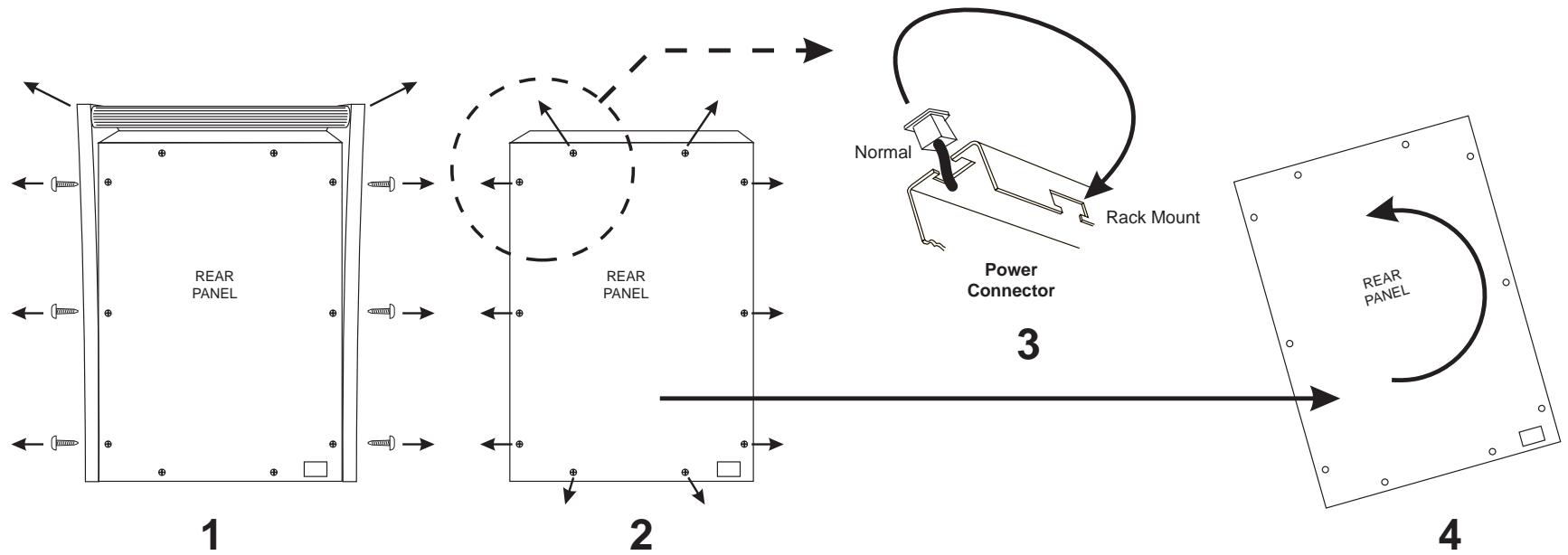
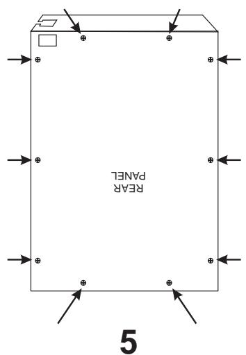
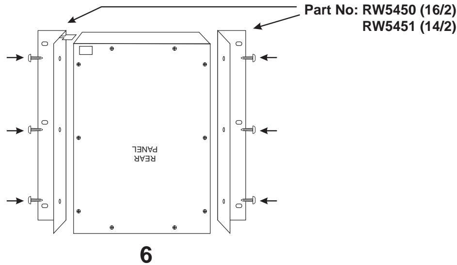
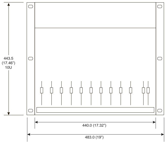
Rack Mounting the Folio F1/Installation in ein Rack/Montage en rack de la Folio F1/Montaggio a rack del mixer Folio F1/Montaje del la Folio F1 en rack
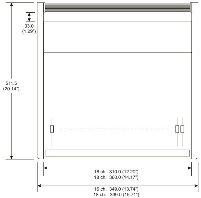
Dimensions
Abmessungen
Dimensions
Dimensioni
Dimensiones


Specifications
Technische Daten
Specifications
Specifiche
Especificaciones
Noise
Mic E.I.N. @ max. gain
20Hz - 20kHz, 150Ω source impedance -129dBu
Aux, Mix & Masters at max., 10 inputs routed, faders down < 85dBu
Crosstalk (@1kHz)
Channel Mute >96dB
Fader Cut-off (rel 0 mark) >96dB
Aux Sends Pots offness >89dB
Frequency Response
Mic/Line Input to any output, 20Hz - 30kHz <1dB
THD+N
Mic sens. -30dBu, +20dBu at all outputs @1kHz <0.006%
Input & Output Impedance
Mic Input 1.8kΩ
Line Input 10kΩ
Stereo Input (Unbalanced RCA Phono) 12kΩ
Stereo Input (Balanced Jack) 10kΩ
Mix & Aux Outputs, Insert Sends 75Ω
Insert Returns >10k
Input & Output Levels
Mic Input max. level +22dBu
Line Input max. level >30dBu
Stereo Input max. level >30dBu
Headphones (@200Ω) 150mW
Weight
Exc. power supply unit 16/2 3.4kg / 7.5 lb
14/2 3.0 kg/6.6 lb

Soundcraft
F1
Console
Mark-up Sheet
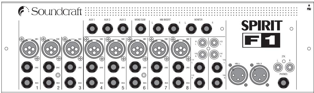
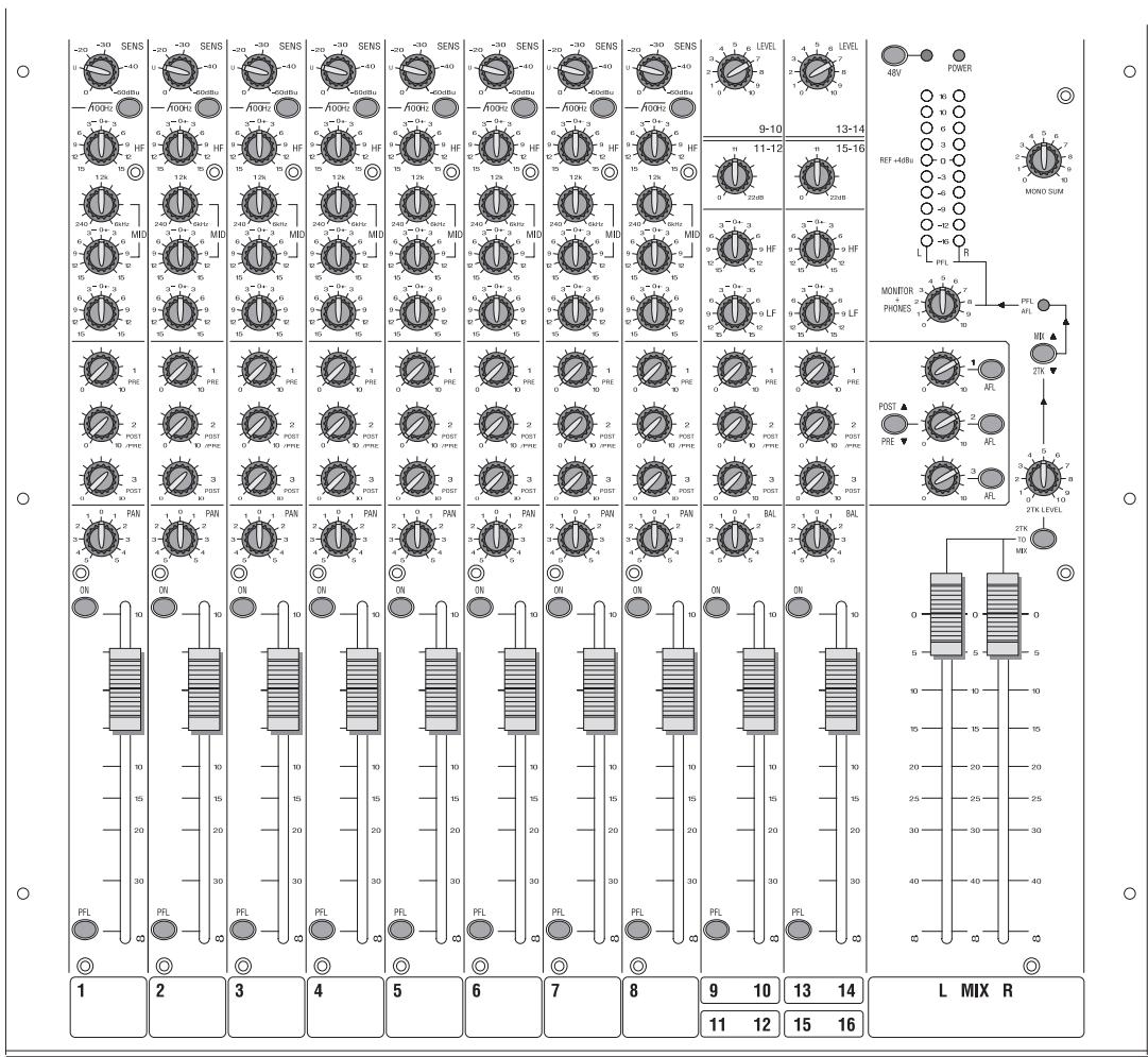
16/2 version shown, 14/2 version also available

Soundcraft

A Harman International Company
www.soundcraft.com
SOUNDCRAFT
Harman International Industries Ltd.,
Cranborne House, Cranborne Road,
Potters Bar, Herts., EN6 3JN U.K.
Tel: +44 (0) 1707 665000
Fax: +44 (0) 1707 660742
EMAIL: info@soundcraft.com
SOUNDCRAFT USA,
1449 Donelson Pike,
Nashville, TN 37217
USA.
Tel: 1-615-360-0471
Fax: 1-615-360-0273
EMAIL: soundcraft-usa@harman.com

This equipment complies
with the EMC directive
89/336/EEC Environment
E1-E4,
93/68/EEC
and LVD 73/23/EEC
For further details contact:
Harman International Industries Ltd.
Cranborne House, Cranborne Road
Potters Bar, Hertfordshire, EN6 3JN, UK
Tel: +44 (0) 1707 665000
Fax: +44 (0) 1707 660742
e-mail: info@soundcraft.com