
MPMI - Mixer SOUNDCRAFT - Free user manual and instructions
Find the device manual for free MPMI SOUNDCRAFT in PDF.
User questions about MPMI SOUNDCRAFT
0 question about this device. Answer the ones you know or ask your own.
Ask a new question about this device
Download the instructions for your Mixer in PDF format for free! Find your manual MPMI - SOUNDCRAFT and take your electronic device back in hand. On this page are published all the documents necessary for the use of your device. MPMI by SOUNDCRAFT.
USER MANUAL MPMI SOUNDCRAFT
Please read this manual carefully before using your mixer for the first time.

This equipment complies with the EMC Directive 2004/108/EC and LVD 2006/95/EC
This product is approved to safety standards:
IEC 60065:2001
EN60065:2002
UL60065 7th Edition: 2003
CAN/CSA-E60065-03
And EMC standards
EN55103-1: 1996 (E2)
EN55103-2: 1996 (E2)
For further details contact:
Harman International Industries Ltd.
Cranborne House, Cranborne Road
Potters Bar, Hertfordshire, EN6 3JN, UK
Tel:
+44(0)1707665000
Fax
+44 (0) 1707660742
e-mail:
soundcraft@harman.com
© Harman International Industries Ltd. 2010
All rights reserved
Parts of the design of this product may be protected by worldwide patents.
Part No. BD10.531000
Soundcraft is a trading division of Harman International Industries Ltd. Information in this manual is subject to change without notice and does not represent a commitment on the part of the vendor. Soundcraft shall not be liable for any loss or damage whatsoever arising from the use of information or any error contained in this manual.
No part of this manual may be reproduced, stored in a retrieval system, or transmitted, in any form or by any means, electronic, electrical, mechanical, optical, chemical, including photocopying and recording, for any purpose without the express written permission of Soundcraft.

Harman International Industries Limited
Cranborne House
Cranborne Road
POTTERS BAR
Hertfordshire
EN63JN
UK
Tel:+44 (0)1707 665000
Fax:+44 (0)1707 660742
http://www.soundcraft.com
Contents
IMPORTANT SAFETY INSTRUCTIONS. 4
SAFETY SYMBOL GUIDE 6
INTRODUCTION 11
THE 60-SECOND GUIDE-MFXi. 12
THE 60-SECOND GUIDE-MPMi. 14
WIRING UP. 16
BLOCKDIAGRAMS 20
MONO INPUT CHANNELS 22
STEREO INPUT CHANNELS 25
MASTER SECTION 28
Lexicon® FX PROCESSOR OVERVIEW (MFXi only) 32
FX OPERATION 33
FXPROCESSORCONTROLS 34
REVERBS. 35
REVERB CONTROLS 36
DELAYS. 37
DELAY CONTROLS 37
MODULATED EFFECTS 38
FACTORY RESET 40
EFFECTS DATA CHART. 41
MFXi & MPMi TYPICAL SPECIFICATIONS 42
USING YOUR MFXi CONSOLE 44
MARK-UP SHEETS 46
FITTING OPTIONAL RACK-MOUNT BRACKETS 48
DIMENSIONS 49
APPLICATIONS 50
TYPICAL CONNECTINGLEADS 54
GLOSSARY 56
WARRANTY 58
IMPORTANT SAFETY INSTRUCTIONS
Read these instructions.
Keep these instructions.
Heed all warnings.
Follow all instructions.
Do not use this apparatus near water.
Clean only with a dry cloth.
Do not block any ventilation openings. Install in accordance with the manufacturer's instructions.
Do not install near any heat sources such as radiators, heat registers, stoves, or other apparatus (including amplifiers) that produce heat.
Do not defeat the safety purpose of a polarised or grounding type plug. A polarised plug has two blades with one wider than the other. A grounding type plug has two blades and a third grounding prong. The wide blade or the third prong are provided for your safety. If the provided plug does not fit into your outlet, consult an electrician for replacement of the obsolete outlet
Protect the power cord from being walked on or pinched particularly at plugs, convenience receptacles and the point where they exit from the apparatus.
Only use attachments/accessories specified by the manufacturer.

Use only with the cart, stand, tripod, bracket or table specified by the manufacturer, or sold with the apparatus. When a cart is used, use caution when moving the cart/ apparatus combination to avoid injury from tip-over.
Unplug this apparatus during lightning storms or when unused for long periods of time.
Refer all servicing to qualified service personnel. Servicing is required when the apparatus has been damaged in any way, such as power-supply cord or plug is damaged, liquid has been spilled or objects fallen into the apparatus, the apparatus has been exposed to rain or moisture, does not operate normally, or has been dropped.
Note: It is recommended that all maintenance and service on the product should be carried out by Soundcraft or its authorised agents. Soundcraft cannot accept any liability whatsoever for any loss or damage caused by service, maintenance or repair by unauthorised personnel.
WARNING: To reduce the risk of fire or electric shock, do not expose this apparatus to rain or moisture.
Do not expose the apparatus to dripping or splashing and do not place objects filled
with liquids, such as vases, on the apparatus.
No naked flame sources, such as lighted candles, should be placed on the apparatus.
Ventilation should not be impeded by covering the ventilation openings with items such as newspapers, table cloths, curtains etc.
THIS APPARATUS MUST BE EARTHED. Under no circumstances should the safety earth be disconnected from the mains lead.
The mains supply disconnect device is the mains plug. It must remain accessible so as to be readily operable when the apparatus is in use.
If any part of the mains cord set is damaged, the complete cord set should be replaced. The following information is for reference only.
The wires in the mains lead are coloured in accordance with the following code:
Earth (Ground): Green and Yellow (US - Green/Yellow)
Neutral: Blue (US - White)
Live (Hot): Brown (US - Black)
As the colours of the wires in the mains lead may not correspond with the coloured markings identifying the terminals in your plug, proceed as follows:
The wire which is coloured Green and Yellow must be connected to the terminal in the plug which is marked with the letter E or by the earth symbol.
The wire which is coloured Blue must be connected to the terminal in the plug which is marked with the letter N
The wire which is coloured Brown must be connected to the terminal in the plug which is marked with the letter L.
Ensure that these colour codes are followed carefully in the event of the plug being changed
This unit is capable of operating over a range of mains voltages as marked on the rear panel.
NOTE: This equipment has been tested and found to comply with the limits for a Class A digital device, pursuant to Part 15 of the FCC Rules. These limits are designed to provide reasonable protection against harmful interference when the equipment is operated in a commercial environment. This equipment generates, uses and can radiate radio frequency energy and, if not installed and used in accordance with the instruction manual, may cause harmful interference to radio communications. Operation of this equipment in a residential area is likely to cause harmful interference in which case the user will be required to correct the interference at his own expense.
This Class A digital apparatus meets the requirements of the Canadian Interference-Caising Equipment Regulations.
For your own safety and to avoid invalidation of the warranty all text marked with these symbols should be read carefully.

WARNING
The lightning flash with arrowhead symbol, is intended to alert the user to the presence of un-insulated "dangerous voltage" within the product's enclosure that may be of sufficient magnitude to constitute a risk of electric shock to persons.

CAUTIONS
The exclamation point within an equilateral triangle is intended to alert the user to the presence of important operating and maintenance (servicing) instructions in the literature accompanying the appliance.

NOTES
Contain important information and useful tips on the operation of your equipment.

HEADPHONES SAFETY WARNING
Contain important information and useful tips on headphone outputs and monitoring levels.
Recommended Headphone Impedance > = 32 Ohms.
CONSIGNES DE SECURITE IMPORTANTES
Thank you for purchasing a Soundcraft MPMi/MFXi mixer. The MPMi and MFXi ranges are our most cost-effective mixing solutions, bringing you all the features and performance that you expect from a Soundcraft product, at an extraordinarily low price. The packaging, in which your console arrived, forms part of the product and must be retained for future use.
Owning a Soundcraft console brings you the expertise and support of one of the industry's leading manufacturers, and the results of over three decades of supporting some of the biggest names in the business. Our knowledge has been attained through working in close contact with leading professionals and institutes to bring you products designed to get the best possible results from your mixing.
Built to the highest standards using quality components and surface mount technology, the MPMi/MFXi is designed to be as easy to use as possible. We have spent years researching the most efficient methods of control for two key reasons:
1) Engineers, musicians, writers and programmers all need to have very few interruptions to the creative process; our products have been designed to be almost transparent, allowing this process to breathe.
2) Whether performing or recording, time is a very expensive and rare commodity. Our products have a user interface which is recognised by millions to be the industry standard because of its efficiency.
The sonic qualities of our products are exemplary - some of the same circuits which are used on our most expensive consoles are employed in the MPMi/MFXi, bringing you the great Soundcraft quality in a small format console without compromise.
You will also be glad to know you have a one year warranty with your product from the date of purchase. The MPMi/MFXi has been designed using the latest high-end software based engineering packages. Every console from Soundcraft has been proven to stand up to all the stress and rigours of modern day mixing environments.
The entire MPMi/MFXi range is manufactured using some of the most advanced techniques in the world, from high density surface mount PCB technology, to computer aided test equipment able to measure signals well outside the range of normal hearing. As each console passes through to be quality checked before packing, there is also a human listening station. Something we have learnt over the years is that the human touch counts - and only by using people can you ensure the product meets the high demands of the user.

ADVICE FOR THOSE WHO PUSH THE BOUNDARIES
Although your new console will not output any sound until you feed it signals, it has the capability to produce sounds which when monitored through an amplifier or headphones can damage hearing over time.
Please take care when working with your audio - if you are manipulating controls which you don't understand (which we all do when we are learning), make sure your monitors are turned down. Remember that your ears are the most important tool of your trade, look after them, and they will look after you.
Most importantly - don't be afraid to experiment to find out how each parameter affects the sound - this will extend your creativity and help you to get the best from your mixer and the most respect from your artists and audience.
THE 60-SECOND GUIDE-MFXi
To get you working as fast as possible, this manual begins with a 60-second guide. Here you can find quick information on any feature of the console. This shows the MFXi console.
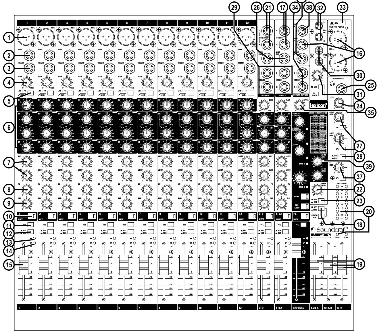
1 MIC INPUT (XLR)

2 LINE INPUT ( 1/4 "Jack)
3 INSERT POINT (1 / 4 "Jack)
4 GAIN CONTROL
5 HPF
6 EQ STAGE
7 AUX 1 & 2 SENDS
8 FX SEND
9 PAN CONTROL
10 MUTE SWITCH
11 PFL
Connect Microphones here. If you are using a condenser mic, ensure phantom power is supplied by pressing the switch at the top of the master section.
WARNING: Do Not apply Phantom Power before connecting a microphone.
Connect Line level sources here, e.g. Synth, Drum Machine, DI etc.
Connect Signal processors here, e.g. Compressor, Gate etc.
Adjust this to increase or decrease the level of the incoming signal.
The high-pass filter reduces the level of bass frequencies only. Use this in live PA situations to reduce stage rumble or 'popping' from mics.
Adjust these controls to change the signal tone (the character of the signal).
Adjust these controls to change the level of the signal to an artist's monitors (headphones/in-ear/stage monitors). Aux 1 send is pre-fade. Aux 2 is globally switchable pre/post fade.
This control sets the level of the post-fade signal being sent to the FX bus; from there it is routed to the FX processor.
Use this control to position the signal within the stereo field.
When this is pressed you will hear no signal from the channel.
When pressed the signal will appear on the monitor and headphone outputs - use this to monitor the post-EQ signal from the channel.

Your MFXi console is equipped with a Kensington® Security slot on the rear panel for use with compatible PC/Laptop security cables.
For more information about the Kensington range of security devices please visit http://us.kensington.com

12 MIX/SUB SWITCH
13 PEAK LED
14 SP LED
15 INPUT CHANNEL FADER
16 MIX OUTPUTS (XLR)
& MONO OUT (1 / 4 "Jack)
17 SUB-GROUP OUTPUTS (1 / 4 "Jack)
18 SUB-GROUP ROUTING
19 MASTER FADERS
20 MAIN METERS
21 MONITOR OUTPUTS (1 / 4 "Jack)
22 MONITOR CONTROL
23 MONITOR SELECT SWITCH
24 PHONES CONTROL
25 HEADPHONES (1 / 4 "Jack)
26 AUX 1 & 2 OUTPUTS (1 / 4 " Jacks)
27 AUX CONTROLS
& AFL SWITCHES
28 AUX 2 POST/PRE SWITCH
29 STEREO INPUTS (1 / 4 Jack)
30 2-TRACK INPUTS (RCA Phono)
31 2-TRACK CONTROLS
32 RECORD OUTPUTS (RCA Phono)
33 PHANTOM POWER
34 STEREO RETURN INPUTS
35 STEREO RETURN CONTROL
36 FX BUS OUTPUT
37 FX CONTROL & AFL SWITCH
38 FOOTSWITCH CONNECTOR
39 LEXICON® FX PROCESSOR
When this switch is up, the channel's post-pan-pot signal is routed to the Mix (left and right) buses. When the switch is depressed, the post-pan-pot signal is routed to the Sub-group (left and right) buses.
This is used to indicate that the signal is close to distorting (clipping) on a specific channel.
The SP LED glows when a signal is present. The feed point for the LED is post-insert, pre-EQ.
This is used to control the level fed to the Mix Bus and post-fade sends.
Connect these to your analogue recording device, or to your amplification system.
These outputs can be connected to a separate amplifier system or to an external processor.
The sub-group mix can be routed to the main mix, in mono or stereo.
These faders control the overall level of the mix and sub-group outputs.
These show the level of the mix outputs. When the master SOLO LED is lit, the meters show the level of the selected AFL/PFL signal.
These are used to feed your monitoring system. This can be directly connected to powered monitors, or indirectly via an amplifier to standard monitors.
This controls the level of the signal sent to your monitoring system.
This switch selects the signal source to be monitored. Note that the 2-TK input can be monitored also, see item 31 below.
This controls the level of the signal sent to the headphones jack socket.
Plug your headphones into this socket. Recommended headphones impedance is 32 ohms or greater.
These outputs can be used to send the channel signal to an artist's monitors (head phones/in-ear/stage monitors), external FX or secondary PA/monitor system.
The rotary controls set the output levels of the two Aux Outputs. The After Fade (AFL) Listen switches route their respective aux output signal to the monitor/ headphones outputs.
This switch globally changes the AUX 2 feed on all the input modules to be either post-fade or pre-fade.
These two pairs of inputs can be used to connect line level stereo inputs from keyboards, sound modules, samplers, computer based audio cards etc. These inputs pass through a stereo channel strip, with EQ, Auxes and a Balance control. Mono sources may be used by plugging into the left jack only.
You can connect the playback from your recording device here.
Use these to control the 2 Track signal. The MONITOR switch sends the signal to the monitor outputs and phones, whilst the TO MIX switch sends it to the main mix.
) You can connect these to the inputs of your recording device.
Press this to globally switch the phantom power (48V) on for condenser microphones.
WARNING: Do Not apply Phantom Power before connecting a microphone.
This pair of inputs accept 3-pole 'A' gauge (TRS) jacks. Use these inputs for sources such as keyboards, drum machines, synths or CDs. The inputs are BALANCED. Mono sources may be used by plugging into the left jack only.
This control sets the level of signal routed to the main mix busses.
This output carries the signal from the FX bus. It could be used as a third Aux Output if desired if the FX Processor is not needed at the time. The FX sends on the inputs channels to the FX bus are always post-fade.
The rotary control regulates the signal level being fed from the FX bus to the FX processor and to the FX BUS OUTPUT socket. The After-Fade Listen (AFL) switch routes this post-FX-control, pre-FX signal to the monitor/headphones outputs.
This is used by the FX Processor, see page 25.
See the information starting on page 24.
THE 60-SECOND GUIDE-MPMI
To get you working as fast as possible, this manual begins with a 60-second guide. Here you can find quick information on any feature of the console..
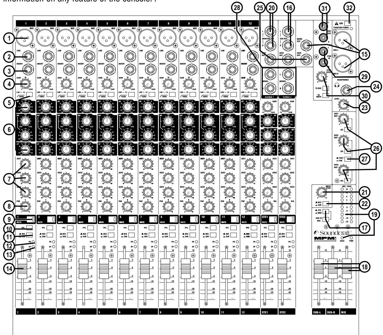
1 MIC INPUT (XLR)

2 LINE INPUT ( 1/4 "Jack")
3 INSERT POINT (1 / 4 "Jack)
4 GAIN CONTROL
5 HPF
6 EQ STAGE
7 AUX SENDS
8 PAN CONTROL
9 MUTE SWITCH
10 PFL
11 MIX/SUB SWITCH
Connect Microphones here. If you are using a condenser mic, ensure phantom power is supplied by pressing the switch at the top of the master section.
WARNING: Do Not apply Phantom Power before connecting a microphone.
Connect Line level sources here, e.g. Synth, Drum Machine, DI etc.
Connect Signal processors here, e.g. Compressor, Gate etc.
Adjust this to increase or decrease the level of the incoming signal.
The high-pass filter reduces the level of bass frequencies only. Use this in live PA situations to reduce stage rumble or 'popping' from mics.
Adjust these controls to change the signal tone (the character of the signal).
Adjust these controls to change the level of the signal to an artist's monitors (headphones/in-ear/stage monitors). Aux 1 send is pre-fade. Aux 2 is globally switchable pre/post fade, Aux 3 send is post-fade
Use this control to position the signal within the stereo field.
When this is pressed you will hear no signal from the channel.
When pressed the signal will appear on the monitor and headphone outputs - use this to monitor the post-EQ signal from the channel.
When this switch is up, the channel's post-pan-pot signal is routed to the Mix (left and right) buses. When the switch is depressed, the post-pan-pot signal is routed to the Sub-group (left and right) buses.

12 PEAK LED
13 SP LED
14 INPUT CHANNEL FADER
15 MIX OUTPUTS (XLR)
MONO OUT (1 / 4 "Jack)
16 SUB-GROUP OUTPUTS (1 / 4 "Jack)
17 SUB-GROUP ROUTING
18 MASTER FADERS
19 MAIN METERS
20 MONITOR OUTPUTS
(1 / 4 Jack)
21 MONITOR CONTROL
22 MONITOR SELECT SWITCH
23 PHONES CONTROL
24 HEADPHONES (1/4 "Jack)
25 AUX 1, 2 & 3 OUTPUTS (1 / 4 "Jacks)
26 AUX CONTROLS
& AFL SWITCHES
27 AUX 2 POST/PRE SWITCH
28 STEREO INPUTS (1/4 "Jack)
29 2-TRACK INPUTS (RCA Phono)
30 2-TRACK CONTROLS
31 Record Outputs (RCA Phono)
32 PHANTOM POWER
This is used to indicate that the signal is close to distorting (clipping) on a specific channel.
The SP LED glows when a signal is present. The feed point for the LED is post-insert, pre-EQ.
This is used to control the level fed to the Mix Bus and post-fade sends.
Connect these to your analogue recording device, or to your amplification & system.
These outputs can be connected to a separate amplifier system or to an external processor.
The sub-group mix can be routed to the main mix, in mono or stereo.
These faders control the overall level of the mix and sub-group outputs.
These show the level of the mix outputs. When the master SOLO LED is lit, the meters show the level of the selected AFL/PFL signal.
These are used to feed your monitoring system. This can be directly connected to powered monitors, or indirectly via an amplifier to standard monitors.
This controls the level of the signal sent to your monitoring system.
This switch selects the signal source to be monitored. Note that the 2-TK input can be monitored also, see item 30 below.
This controls the level of the signal sent to the headphones jack socket.
Plug your headphones into this socket. Recommended headphones impedance is 32 ohms or greater.
These outputs can be used to send the channel signal to an artist's monitors
(headphones/in-ear/stage monitors), external FX or secondary PA/monitor system.
The rotary controls set the output levels of the three Aux Outputs. The After
Fade Listen (AFL) switches route their respective aux output signal to the monitor/ headphones outputs.
This switch globally changes the AUX 2 feed on all the input modules to be either post-fade or pre-fade.
These two pairs of inputs can be used to connect line level stereo inputs from keyboards, sound modules, samplers, computer based audio cards etc. These inputs pass through a stereo channel strip, with EQ, Auxes and a Balance control. Mono sources may be used by plugging into the left jack only.
You can connect the playback from your recording device here.
Use these to control the 2 Track signal. The Monitor switch sends the signal to the monitor outputs and phones, whilst the TO MIX switch sends it to the main mix.
You can connect these to the inputs of your recording device.
Press this to globally switch the phantom power (48V) on for condenser microphones.
WARNING: Do Not apply Phantom Power before connecting a microphone.

Your MFXi console is equipped with a Kensington® Security slot on the rear panel for use with compatible PC/Laptop security cables.
For more information about the Kensington range of security devices please visit http://us.kensington.com
INPUTS
Balanced Mic XLR
Unbalanced Mic XLR
3 pole jack 2 pole jack
Balanced Unbalanced
Inserts
HCA Phono Plug
2-Track Return L & R.
WIRING UP
Mic Input
The MIC input accepts XLR-type connectors and is designed to suit a wide range of BALANCED or UNBALANCED low-level signals, whether from delicate vocals requiring the best low-noise performance, or drum kits needing maximum headroom. Professional dynamic, condenser or ribbon mics are best because these will be LOW IMPEDANCE. While you can use low-cost HIGH IMPEDANCE mics, you do not get the same degree of immunity to interference on the microphone cable and as a result the level of background noise may be higher. If you turn the PHANTOM POWER on, the socket provides a suitable powering voltage for professional condenser mics.

DO NOT use UNBALANCED sources with the phantom power switched on. The voltage on pins 2 & 3 of the XLR connector may cause serious damage. BALANCED dynamic mics may normally be used with phantom power switched on (contact your microphone manufacturer for guidance)
The input level is set using the input GAIN knob.
The LINE input offers the same gain range as the MIC input, but at a higher input impedance, and is 15dB less sensitive. This is suitable for most line level sources.

WARNING!
Start with the input GAIN knob turned fully anticlockwise when plugging high level sources into the LINE input to avoid overloading the input channel or giving you a very loud surprise!
Line Input
Accepts 3-pole 6.35mm (1/4") jacks, or 2-pole mono jacks which will automatically ground the 'cold' input. Use this input for sources other than mics, such as keyboards, drum machines, synths, tape machines or DI boxes. The input is BALANCED for low noise and immunity from interference, but you can use UNBALANCED sources by wiring up the jacks as shown, although you should then keep cable lengths as short as possible to minimise interference pick-up on the cable. Note that the ring must be grounded if the source is unbalanced. Set the input level using the GAIN knob, starting with the knob turned fully anticlockwise. Unplug any MIC connection when using the LINE input.
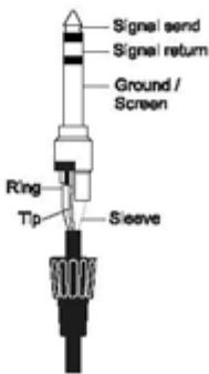
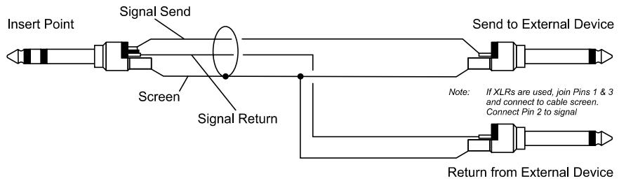
Insert Point
The unbalanced, pre-EQ insert point is a break in the channel signal path, allowing limiters, compressors, special EQ or other signal processing units to be added in the signal path. The Insert is a 3-pole 6.35mm (1/4") jack socket which is normally bypassed. When a jack is inserted, the signal path is broken, just before the EQ section.
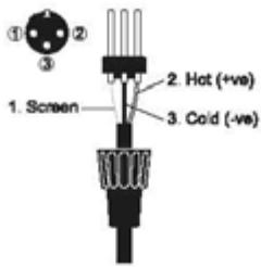
The signal from the channel appears on the TIP of the plug and is returned on the RING, with the sleeve as a common ground.
The Send may be tapped off as an alternative pre-fade, pre-EQ direct output if required, using a lead with tip and ring shorted together so that the signal path is not interrupted.
A 'Y' lead may be required to connect to equipment with separate send and return jacks as shown below:
Stereo Inputs STEREO 1/2
These accept 3-pole 6.35mm (1/4") jacks, or 2-pole mono jacks which will automatically ground the 'cold' input. Use these inputs for sources such as keyboards, drum machines, synths, tape machines or as returns from processing units. The input is BALANCED for low noise and immunity from interference, but you can use UNBALANCED sources by wiring up the jacks as shown, although you should then keep cable lengths as short as possible to minimise interference pick-up on the cable. Note that the ring must be grounded if the source is unbalanced.
Mono sources can be fed to both paths by plugging into the Left jack only.
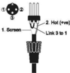
Mix Outputs
The MIX outputs are on XLR's, wired as shown, and incorporate impedance balancing, allowing long cable runs to balanced amplifiers and other equipment.
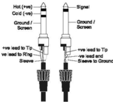
Aux and FX Bus Outputs
The Aux and FX Bus outputs are on 3-pole 6.35mm (1/4") jack sockets, wired as shown on the left, and are balanced, allowing long cable runs to balanced amplifiers and other equipment.
Headphones
The PHONES output is a 3-pole 6.35mm (1/4") jack, wired as a stereo output as shown, ideally for headphones of 32 or greater. 8 headphones are not recommended.
Polarity (Phase)
You will probably be familiar with the concept of polarity in electrical signals and this is of particular importance to balanced audio signals. Just as a balanced signal is highly effective at cancelling out unwanted interference, so two microphones picking up the same signal can cancel out, or cause serious degradation of the signal if one of the cables has the +ve and -ve wires reversed. This phase reversal can be a real problem when microphones are close together and you should therefore always take care to connect pins correctly when wiring audio cables.
Grounding and Shielding
For optimum performance use balanced connections where possible and ensure that all signals are referenced to a solid, noise-free earthing point and that all signal cables have their screens connected to ground. In some unusual circumstances, to avoid earth or ground 'loops' ensure cable screens and other signal earths are connected to ground only at their source and not at both ends.
If the use of unbalanced connections is unavoidable, you can minimise noise by following these wiring guidelines:
- On INPUTS, unbalance at the source and use a twin screened cable as though it were balanced.
- On OUTPUTS, connect the signal to the +ve output pin, and the ground of the output device to -ve. If a twin screened cable is used, connect the screen only at the mixer end.
- Avoid running audio cables or placing audio equipment close to thyristor dimmer units or power cables.
- Noise immunity is improved significantly by the use of low impedance sources, such as good quality professional microphones or the outputs from most modern audio equipment. Avoid cheaper high impedance microphones, which may suffer from interference over long cable runs, even with well-made cables.
Grounding and shielding is still seen as a black art, and the suggestions above are only guidelines. If your system still hums, an earth/ground loop is the most likely cause. Two examples of how an earth loop can occur are shown below.

Warning! Under NO circumstances must the AC power mains earth be disconnected from the mains lead.
PROBLEM SOLVING
Basic problem solving is within the scope of any user if a few basic rules are followed.
Get to know the Block Diagram of your console (see page 14).
- Get to know what all controls and/or connections in the system are supposed to do.
- Learn where to look for common trouble spots.
The Block Diagram is a representative sketch of all the components of the console, showing how they connect together and how the signal flows through the system. Once you have become familiar with the various component blocks you will find the Block Diagram is quite easy to follow and you will have gained a valuable understanding of the internal structure of the console.
Each component has a specific function and only by getting to know what each part is supposed to do will you be able to tell if there is a genuine fault! Many “faults” are the result of incorrect connection or control settings which may have been overlooked. Basic Troubleshooting is a process of applying logical thought to the signal path through the console and tracking down the problem by elimination.
- Swap input connections to check that the source is really present. Check both Mic and Line inputs.
- Eliminate sections of the channel by using the insert point to re-route the signal to other inputs that are known to be working.
- Route channels to different outputs or to auxiliary sends to identify problems on the Master section.
- Compare a suspect channel with an adjacent channel which has been set up identically. Use PFL to monitor the signal in each section.
- Insert-point contact problems may be checked by using an insert bypass jack with tip and ring shorted together as shown below. If the signal appears when the jack is inserted it shows that there is a problem with the normaling contacts on the jack socket, caused by wear or damage, or often just dirt or dust. Keep a
few in your gig tool box.
Dummy Insert Bypass Jack
If in doubt please contact Soundcraft customer support.
PRODUCTS UNDER WARRANTY
UK customers should contact their local dealer.
Customers outside the UK are requested to contact their territorial distributor who is able to offer support in the local time zone and language. Please see the distributor listings on our website (www.soundcraft.com) to locate your local distributor.
OUT-OF-WARRANTYPRODUCTS
For out-of-warranty consoles purchased in the United Kingdom, please contact the Customer Services Department (e-mail: soundcraft.csd@harman.com) at the factory in Potters Bar, Hertfordshire: Telephone +44 (0)1707 665000.
For all other out-of-warranty consoles, please contact the appropriate territorial distributor. When mailing or faxing please remember to give as much information as possible. This should include your name, address and a daytime telephone number. Should you experience any difficulty please contact Customer Services Department (e-mail: soundcraft.csd@harman.com)
MONO INPUT CHANNELS (MFXi shown)
1 Mic Input
The MIC input accepts XLR-type connectors and is designed to suit a wide range of BALANCED or UNBALANCED signals. Professional dynamic, condenser or ribbon mics are best because these will be LOW IMPEDANCE. You can use low-cost HIGH IMPEDANCE mics, but the level of background noise will be higher. If you turn the PHANTOM POWER on (top right-hand side of the mixer) the socket provides a suitable powering voltage for professional condenser mics.

ONLY connect condenser microphones with the +48V powering OFF, and ONLY turn the +48V powering on or off with all output faders DOWN, to prevent damage to the mixer or external devices.
TAKE CARE when using unbalanced sources, which may be damaged by the phantom power voltage on pins 2 & 3 of the XLR connector.
Unplug any mics if you want to use the LINE Input. The input level is set using the GAIN knob.
2 Line Input
Accepts 3-pole 6.35mm (1/4") jacks. Use this input for sources other than mics, such as keyboards, drum machines, synths, tape machines or DI'd guitars. The input is BALANCED for low noise and top quality from professional equipment, but you can use UNBALANCED sources by wiring up the jacks as shown in the 'wiring up' section, although you should then keep cable lengths as short as possible. Unplug anything in the MIC input if you want to use this socket. Set the input level using the GAIN knob.
3 High-pass Filter
Pressing this switch activates the high-pass filter. This reduces the level of bass frequencies only. Use this in live PA situations to reduce stage rumble or 'popping' from mics.
4 Insert Point
The unbalanced, pre-EQ insert point is a break in the channel signal path, allowing limiters, compressors, special EQ or other signal processing units to be added in the signal path. The Insert is a 3-pole 6.35mm (1/4") jack socket which is normally bypassed. When a jack is inserted, the signal path is broken, just before the EQ section.
The Send may also be tapped off as an alternative pre-fade, pre-EQ direct output if required, using a lead with tip and ring shorted together so that the signal path is not interrupted (see below).
5 Gain
This knob sets how much of the source signal is sent to the rest of the mixer. Too high, and the signal will distort as it overloads the channel. Too low, and the level of any background hiss will be more noticeable and you may not be able to get enough signal level to the output of the mixer.
Note that some sound equipment, particularly that intended for domestic use, operates at a lower level (-10dBV) than professional equipment and will therefore need a higher gain setting to give the same output level.
See "Initial Setup" on page 33 to learn how to set GAIN correctly.
6 Equaliser
The Equaliser (EQ) allows fine manipulation of the sound, particularly to improve the sound in live PA applications where the original signal is often far from ideal and where slight boosting or cutting of particular frequencies can really make a difference to clarity. There are three sections giving the sort of control usually only found on much larger mixers. The EQ knobs can have a dramatic effect, so use them sparingly and listen carefully as you change any settings so that you get to know how they affect the sound.
HF EQ
Turn to the right to boost high (treble) frequencies above 12kHz by up to 15dB, adding crispness to cymbals, vocals and electronic instruments. Turn to the left to cut by up to 15dB, reducing hiss or excessive sibilance which can occur with certain types of microphone. Set the knob in the centre-detented position when not required.
MID EQ
There are two knobs which work together to form a SWEPT MID EQ. The lower knob provides 15dB of boost and cut, just like the HF EQ knob, but the frequency at which this occurs can be set by the upper knob over a range of 150Hz to 3.5kHz. This allows some truly creative improvement of the signal in live situations, because this mid band covers the range of most vocals. Listen carefully as you use these controls together to find how particular characteristics of a vocal signal can be enhanced or reduced. Set the lower knob to the centre-detented position when not required.
LF EQ
Turn to the right to boost low (bass) frequencies below 80Hz by up to 15dB, adding warmth to vocals or extra punch to synths, guitars and drums. Turn to the left to cut low frequencies by up to 15dB for reducing hum, stage rumble or to improve a mushy sound. Set the knob to the centre-detented position when not required.
7 Aux Sends
These are used to set up separate mixes for FOLDBACK, EFFECTS or recording, and the combination of each Aux Send is mixed to the respective Aux Output. For Effects it is useful for the signal to fade up and down with the fader (this is called POST-FADE), but for Foldback or Monitor feeds it is important for the send to be independent of the fader (this is called PRE-FADE).
AUX SEND 1 is fixed pre-fade, AUX 2 is globally switchable between pre and post-fade (see master section on page 20). On the MPMi, Aux 3 is fixed post-fader.
AUX 3 SEND (MPMi only) Aux 3 is fixed post-fade.
8 FX SEND (MFXi only)
This control sets the level of the post-fade signal being sent to the FX bus; from there it is routed to the FX processor. The FX Send is fixed post-fader.
9 PAN
This control sets the amount of the channel signal feeding the Left and Right MIX buses, allowing you to move the source smoothly across the stereo image. When the control is turned fully left or right you are able to route the signal at unity gain to either left or right outputs individually.
10 MUTE
All outputs from the channel (except inserts) are on when the MUTE switch is released and muted when the switch is down, allowing levels to be pre-set before the signal is required. The MUTE switch's inbuilt LED glows when the channel is muted.
11 INPUT CHANNEL FADER
The 60mm FADER gives you smooth control of the overall signal level in the channel strip, allowing precise balancing of the various source signals being mixed to the Master Section. It is important that the input level is set correctly to give maximum travel on the fader which should normally be used at around the "0" mark. See the "Initial Setup" section on page 33 for help in setting the right level.
12 PFL
When the latching PFL switch is pressed, the pre-fade pre-mute signal is fed to the headphones, control room output and meters, where it replaces the MIX. The SOLO LED on the Master section illuminates to warn that a PFL is active. This is a useful way of listening to any required input signal without interrupting the main mix, for making adjustments or tracing problems. When PFL is pressed anywhere on the console, the Control Room outputs automatically switch from monitoring the Mix Outputs.
13 PEAK LED
This LED will light when the signal level approaches clipping at any of the three monitored points: PRE-EQ, POST-EQ and POST-FADE.
14 SIGNAL PRESENT (SP) LED
The SP LED glows when a signal is present. The feed point for the LED is pre-EQ.
15 MIX/SUB
When this switch is up, the channel's post-pan-pot signal is routed to the Mix (left and right) buses. When the switch is depressed, the post-pan-pot signal is routed to the Sub-group (left and right) buses.
It is sometimes useful to route several inputs to the sub-group buses, e.g. all the mics for a drum kit, or all the vocal mics for a choir. These signals can then be fed to the main mix at the master section. By doing this the levels of all of the grouped inputs can be changed together by using the group faders instead of having to adjust all of the individual input faders, although, of course, the individual channel faders will have to be adjusted to start with.
STEREO INPUT CHANNELS (MFXi shown)
1 INPUTS STEREO 1/2
These inputs accept 3-pole 6.35mm (1/4") jacks. Use these inputs for sources such as keyboards, drum machines, synths, tape machines or processing units. The inputs are BALANCED for low noise and top quality from professional equipment, but you can use UNBALANCED sources by wiring up the jacks as shown in the 'Wiring Up' section earlier in this manual, although you should then keep cable lengths as short as possible. Mono sources may be used by plugging into the left jack only.
2 GAIN
The GAIN control sets the level of the channel signal.
3 EQUALISER
HF EQ
Turn to the right to boost high (treble) frequencies, adding crispness to percussion from drum machines, synths and electronic instruments. Turn to the left to cut these frequencies, reducing hiss or excessive brilliance. Set the knob in the centre-detented position when not required. The control has a shelving response giving 15dB of boost or cut at 12kHz .
MF EQ
Turn to the right to boost mid frequencies by up to 15dB, turn to the left to cut these frequencies by up to 15dB. The centre frequency of the MF EQ is 720Hz.
LF EQ
Turn to the right to boost low (bass) frequencies, adding extra punch to synths, guitars and drums. Turn to the left to reduce hum, boominess or improve a mushy sound. Set the knob to the centre-detented position when not required. The control has a shelving response giving 15dB of boost or cut at 80Hz .
4 AUX SENDS
These are used to set up separate mixes for FOLDBACK, EFFECTS or recording, and the combination of each Aux Send is mixed to the respective Aux Output at the rear of the mixer. For Effects it is useful for the signal to fade up and down with the fader (this is called POST-FADE), but for Foldback or Monitor feeds it is important for the send to be independent of the fader (this is called PRE-FADE).
AUX SEND 1 is fixed pre-fade, AUX 2 is globally switchable between pre and post-fade (see master section on page 20). On the MPMi, Aux 3 is fixed post-fader. The send pots are fed with a mono sum of the L & R signals.
AUX 3 SEND (MPMi)
Aux 3 is fixed post-fader.
5 FX SEND (MFXi)
This control sets the level of the post-fade signal being sent to the FX bus; from there it is routed to the FX processor. The FX Send is always post-fader.
6 BALANCE
This control sets the amount of the channel signal feeding the Left and Right MIX buses, allowing you to balance the source in the stereo image. When the control is turned fully right or left you feed only that side of the signal to the mix. Unity gain is provided by the control in the centre-detented position.
7 MUTE
All outputs from the channel are enabled when the MUTE switch is released and muted when the switch is down. The MUTE switch's inbuilt LED glows when the channel is muted.
8 FADER
The 60mm FADER gives you smooth control of the overall signal level in the channel strip, allowing precise balancing of the various source signals being mixed to the Master Section. It is important that the input level is set correctly to give maximum travel on the fader which should normally be used at around the "0" mark. See the "Initial Setup" section on page 33 for help in setting the right level.
9 PFL
When the latching PFL switch is pressed, the pre-fade pre-mute signal is fed in mono to the headphones, control room output and meters, where it replaces the MIX. The SOLO LED on the Master section illuminates to warn that a PFL is active. The Left and Right meters display the PFL signal in mono. This is a useful way of listening to any required input signal without interrupting the main mix, for making adjustments or tracing problems.
10 CHANNEL PEAK LED
This LED will light when the signal level approaches clipping at any of the two monitored points: POST-EQ and POST-FADE.
11 SIGNAL PRESENT (SP) LED
The SP LED glows when a signal is present. The feed point for the LED is pre-EQ.
12 MIX/SUB
When this switch is up, the channel's post-fade signal is routed to the Mix (left and right) buses. When the switch is depressed, the post-fade signal is routed to the Subgroup (left and right) buses.
MASTER SECTION (MFXi)
MASTER SECTION (MPMi)
1 POWER INDICATOR
This LED lights to show when power is connected to the console.
2 PHANTOM POWER
Many professional condenser mics need PHANTOM POWER, which is a method of sending a powering voltage down the same wires as the mic signal. Press the switch to enable the +48V power to all of the MIC inputs. The adjacent LED illuminates when the power is active.

WARNING: TAKE CARE when using unbalanced mics which may be damaged by the phantom power voltage. Balanced dynamic mics can normally be used with phantom power switched on (contact your microphone manufacturer for guidance). Mics should always be plugged in, and all output faders set to minimum before switching the Phantom Power ON to avoid damage to external equipment.
2-TRACK
3 2-TRACK IN
These two RCA phono sockets are unbalanced Left and Right line-level inputs, used for connecting a playback device.
This adjusts the signal level from the 2-Track inputs.
5 2-TRACK TO MIX
Press this switch to route the 2-Track input signals to the MIX Left/Right bus. The level is set with the 2-Track level control.
MONITOR SOURCE
The following two switches select the signal source(s) to be monitored.
6 MIX/SUB
Press this switch down to monitor the sub-group outputs. Release this switch to monitor the main mix outputs.
7 2-TRACK
Press this switch to monitor the 2-Track input signal.
MONITOR OUT
8 MONITOR OUTPUT LEVEL
This control sets the signal level fed to the MONITOR LEFT & RIGHT outputs.
9 MONITOR OUTPUTS
The Monitor Outputs are on 3-pole 6.35mm (1/4") jacks and are balanced.
10 HEADPHONES LEVEL
This control sets the level of the Headphone output.
11 HEADPHONES SOCKET
The PHONES output is a 3-pole 6.35mm (1/4") jack, wired as a stereo output, ideally for headphones of 32 or greater. 8 headphones are not recommended.
12 METERS & SOLO LED
The three-colour peak reading BARGRAPH METERS normally show the level of the signal(s) selected by the monitor source-select switches, giving you a constant warning of excessive peaks in the signal(s) which might cause overloading. Aim to keep the signal within the amber segments at peak levels for best performance. Similarly, if the output level is too low and hardly registering at all on the meters, the level of background noise may become significant. Take care to set up the input levels for best performance.
When any AFL/PFL switch is pressed, the meters switch to show the selected AFL/PFL signal on both meters, in mono; the SOLO LED also lights.
MIX & SUB-GROUP OUTPUTS
13 MIX FADER
The MIX FADER sets the final level of the Mix outputs. This should normally be set close to the '0' mark if the input GAIN settings have been correctly set, to give maximum travel on the fader for smoothest control.
14 SUB FADERS
This pair of faders sets the final levels of the Sub-group outputs. These should normally be set close to the '0' mark if the input GAIN settings have been correctly set, to give maximum travel on the faders for smoothest control.
15 SUB TO MIX
This switch routes the Sub-L and Sub-R signals to the main mix.
16 STEREO/MONO
If this switch is depressed a mono sum of the sub-group signals is routed to the main mix.
17 MIX OUTPUTS
The Mix LEFT and RIGHT outputs are sent from the XLR sockets as balanced signals.
18 MONO OUTPUT
A mono sum of the mix left and right signals is output on this balanced 3-pole 6.35mm (1/4") jack socket.
19 SUB OUTPUTS
The Sub-L and Sub-R signals are output on these balanced 3-pole 6.35mm (1/4") jack sockets.
20 RECORD OUTPUTS
These two RCA outputs carry a copy of the MIX L and MIX R signals. They allow the use of a recording device, e.g. DAT player, Minidisc, Cassette tape recorder etc.
AUX
21 AUX MASTERS
These controls set the output levels of the Aux Outputs. (1 & 2 on MFXi, 1, 2 & 3 on MPMi)
22 AFL
These After Fade Listen switches route their respective aux output signal to the headphones, control room output and meters, where it replaces the MIX. The SOLO LED on the Master section illuminates to warn that an AFL is active. There are 2 AFL switches for Auxes 1 &2 on the MFXi, and three for Auxes 1, 2 and 3 on the MPMi.
23 PRE/POST SWITCH
This switch globally selects the AUX 2 feeds on all the input modules to be either pre-fade or post-fade.
24 AUX OUTPUTS 1 & 2 (and 3 on MPMi)
These outputs are on 3-pole 6.35mm (1/4") jacks and are balanced.
The following controls are found on the MFXi Console only
FX
For detailed instructions on using the FX Processor see the section which starts on the next page.
25 FX MASTER
This control regulates the signal level being fed from the FX bus to the FX processor and to the FX BUS OUTPUT socket.
26 FX AFL
When the latching AFL switch is pressed, the post-FX-Master (25), pre-FX signal is fed to the headphones, control room output and meters, where it replaces the MIX. The SOLO LED on the Master section illuminates to warn that an AFL is active.
27 FX BUS OUTPUT
This output carries the signal from the FX bus. It could be used as a third Aux Output if desired if the FX Processor is not needed at the time. The FX sends on the input channels to the FX bus are always post-fade. (on the MPMi, the FX Send output becomes Aux 3 output)
28 MUTE FX (FOOTSWITCH)
Using a single pole, momentary footswitch inserted into the MUTE FX input the effects processor can be muted/un-muted.
STEREO RETURN - MFXi Console only
29 STEREO RETURN INPUTS
This pair of inputs accept 3-pole 'A' gauge (TRS) jacks. Use these inputs for sources such as keyboards, drum machines, synths or CDs. The inputs are BALANCED. Mono sources may be used by plugging into the left jack only.
30 STEREO RETURN LEVEL
This control sets the level of signal routed to the main mix busses.
Lexicon® FX PROCESSOR OVERVIEW
The effects within the console have been designed with both live sound reinforcement and home recording in mind. Featuring the deep, rich reverb algorithms that Lexicon® are renowned for the effects processor offers increased versatility and high quality effects, all instantly accessible via the extremely intuitive front panel controls. The effects processor has 32 programs which are held in two banks of 16 programs which can be stored to allow you to create your own custom effect settings.
Front panel controls include a Program Select knob, Tempo and Store buttons, and three independent Parameter knobs that provide instant access and control over the most critical parameters for the selected effect. The table on page 32 lists the functions of the Parameter knobs for each fx program.
Note: When the console is powered up the program recalled will always be the selected program in BANK A.
FX OPERATION
Select and Load a Program
Turn the Program Select knob to choose a program. Note that the console has 32 programs which are held in two banks of 16 programs. There are individual BANK A and BANK B LED's to indicate which bank is currently active. When turning the rotary Program Select knob through 360 degrees (a full rotation) the selected bank will alternate between BANK A and BANK B.
Set Audio Levels
- Set the gain on the input channel appropriate to the source (vocal microphone, guitar, keyboard, etc.).
- Set the FX send on the input channel to the 2 o'clock position.
- Set the FX Master level to the 2 o'clock position. Set the EFFECTS Fader on the FX section to the fully down position.
- Provide source signal (by speaking or singing into the microphone, playing guitar, keyboard, etc.) on the selected channel.
- Turn up the FX Send level on the channel until the Red CLIP LED in the FX Panel lights only occasionally. If the red Input LED stays lit, too much signal is being sent to the effect processor; reduce the FX Master on the FX Send on the input channel.
- Raise the EFFECTS Fader towards the 0dB position to feed the required level of FX Processor output signal to the mix.
- To increase or decrease the amount of effect on the signal, adjust the FX Send level on the channel that you want affected.
FX PROCESSOR CONTROLS (MFXi only)
- Tempo Button - Tapping this button twice sets the Delay Time of the selected program. The LED flashes to indicate current tempo. Can be tapped in time with music source to synchronise the delay.
- Store Button - Stores program modifications to one of the program locations. Press and hold for three seconds will store the preset in the current location. The LED will flash rapidly during the store operation and then stay illuminated for 1 second to show the operation is complete.
- Pre Delay / Time/ Speed Knob - Controls Pre Delay of the reverbs or the first parameter (time or speed related) of the selected effect. The LED illuminates when the parameter matches the stored setting.
- Decay / Feedback/Depth Knob - Controls Decay of the reversors or the second parameter (feedback or depth related) of the selected effect. The LED illuminates when the parameter matches the stored setting.
- Variation - Controls Liveliness or Diffusion (depending on the reverb selected) or the third parameter of the selected effect. The LED illuminates when the parameter matches the stored setting.
- Program Select Knob - Navigates through programs, turning to the required program will initiate the loading of the program which take approximately 1 second. The knob can be rotated clockwise or anticlockwise and will alternate between BANK A and BANK B every full rotation. The current bank is shown by its illuminated LED, which flashes if the FX processor is muted. There is a handy aide memoir of the programs printed on the front panel.
- Clip LED – This LED illuminates when either the incoming audio or the processed audio (within the effect processor) overloads, and causes distortion of the signal. If this illuminates reduce the FX Master Level (item 25, page 20).
Footswitch Input (not shown on diagram, see item 28 on page 20) - Using a single pole, momentary footswitch inserted into the MUTE FX input the effects processor can be muted/un-muted. - MUTE - This switch mutes the output of the FX processor. It doesn't mute the PFL signal.
- FX TO AUX 1 - This pot routes a pre-fade signal to the Aux 1-pre bus.
- FX TO AUX 2- This pot routes a pre-fade and a post-fade signal to the Aux 2-pre and Aux 2-post busses respectively.
- EFFECTS FADER - This fader controls the level of the signal, from the FX processor, routed to the main mix.
- PFL - This switch routes a post-effects processor signal to the monitor system.
FX BUS OUT (not shown on diagram, see item 27 on page 20) - This output carries the signal from the FX bus. It could be used as a third Aux Output if desired.
- 'SP' LED - This indicates when a signal is present.
REVERBS
Reverberation (or "reverb" for short) is the complex effect created by the way we perceive sound in an enclosed space. When sound waves encounter an object or boundary, they don't just stop. Some of the sound is absorbed by the object, but most of the sound is reflected or is diffused. In an enclosed space, reverb is dependent on many features of that space, including the size, shape and the type of materials that line the walls. Even with closed eyes, a listener can easily tell the difference between a closet, a locker room and a large auditorium. Reverb is a natural component of the acoustic experience, and most people feel that something is missing without it.
Hall Reverb
A Hall is designed to emulate the acoustics of a concert hall – a space large enough to contain an orchestra and an audience. Because of the size and characteristics, Halls are the most natural-sounding reverbs, designed to remain “behind” the direct sound – adding ambience and space, but leaving the source unchanged. This effect has a relatively low initial echo density which builds up gradually over time. Vocal Hall and Drum Hall reverbs are specifically tailored for those uses. Vocal Hall has as lower overall diffusion which works well with program material that has softer initial transients like a voice. Drum Hall has a higher diffusion setting which is necessary to smooth out faster transient signals found in drums and percussion instruments. In addition to general instrumental and vocal applications, the Hall program is a good choice for giving separately recorded tracks the sense of belonging to the same performance.
Plate Reverb
A Plate reverb is a large, thin sheet of metal suspended upright under tension on springs. Transducers attached to the plate transmit a signal that makes the plate vibrate, causing sounds to appear to be occurring in a large, open space. The Plates in the FX processor model the sound of metal plates with high initial diffusion and a relatively bright, colored sound. Plate reversals are designed to be heard as part of the music, mellowing and thickening the initial sound. Plate reversals are often used to enhance popular music, particularly percussion.
Room Reverb
Room produces an excellent simulation of a very small room which is useful for dialog and voiceover applications. Room is also practical when used judiciously for fattening up high energy signals like electric guitar amp recordings. Historically, recording studio chambers were oddly shaped rooms with a loudspeaker and set of microphones to collect ambience in various parts of the room.
Chamber Reverb
Chamber programs produce even, relatively dimensionless reverberation with little color change as sound decays. The initial diffusion is similar to the Hall programs. However, the sense of size and space is much less obvious. This characteristic, coupled with the low color of the decay tail, makes these programs useful on a wide range of material - especially the spoken voice, to which Chamber programs add a noticeable increase in loudness with low color.
Gated Reverb
Gated reverb is created by feeding a reverb, such as a metal plate, through a gate device. Decay Time is set to instant, while Hold Time varies duration and sound. The Gated reverb provides a fairly constant sound with no decay until the reverb is cut off abruptly. This program works well on percussion - particularly on snare and toms; be sure to experiment with other sound sources as well.
Reverse Reverb
Reverse reverb works in the opposite fashion from normal reverb. Whereas a normal reverb has the loudest series of reflections heard first that then become quieter over time, the Reverse reverb has the softest reflections (essentially the tail of the reverb) heard first, and then grows louder over time until they abruptly cut off.
Ambience Reverb
Ambience is used to simulate the effect of a small or medium sized room without noticeable decay. It is often used for voice, guitar or percussion.
Studio Reverb
Much like Room reverb, Studio produces an excellent simulation of smaller, well controlled acoustic spaces, characteristic of the main performance areas in recording studios. Studio is also useful with dialog and voiceover applications as well as individual instrument and electric guitar tracks.
Arena Reverb
Arena reverb emulates a huge physical space such as an indoor sports venue or stadium. The characteristics of Arena reverb are long secondary reflection times and a reduced amount of high frequency content. Arena is a mostly mid- and low frequency dominant reverb, and is an ideal selection for "special effect" type applications that require extremely long reverb times. It is not a good choice for a very busy mix, since it can reduce intelligibility.
Spring Reverb
A Spring reverb is created by a pair of piezoelectric crystals—one acting as a speaker and the other acting as a microphone—connected by a simple set of springs. The characteristic 'boing' of a spring is an important component of many classic rock and rockabilly guitar sounds.
REVERB CONTROLS
Pre Delay
Creates an additional time delay between the source signal and the onset of reverberation. This control is not intended to precisely mimic the time delays in natural spaces, as the build-up of reverberation is gradual, and the initial time gap is usually relatively short. For the most natural effect, the Pre Delay values should be set in the range of 10-25 milliseconds. However, if a mix is very busy or overly cluttered, increasing the Pre Delay time may help clarify it, and set each instrument apart from each other.
Decay
Controls the amount of time the reverb can be heard. Higher settings increase reverberation times which are usually associated with larger acoustical environments, but can decrease intelligibility. Lower settings shorten reverb times and should be used when a smaller apparent space or a more subtle effect is desired.
Liveliness
Adjusts the amount of high frequency content in the reverberation tails. Higher settings increase high frequency response, creating brighter revers; lower settings create darker revers with more bass frequency emphasis.
Diffusion
Controls the initial echo density. High settings of Diffusion result in high initial echo density, and low settings cause low initial density. In a real-world situation, irregular walls cause high diffusion, while large flat walls cause low diffusion. For drums and percussion, try using higher Diffusion settings.
Shape
This control helps give a sense of both room shape and room size. Low values for Shape keep the majority of sound energy in the early part of the reverb tail. High values move the energy to later in the reverb, and are helpful in creating the sense of a strong rear wall or "backslap.
Boing
This is a unique parameter to the Spring reverb, designed to increase or decrease the amount of spring rattle that is a physical characteristic of spring tank reversbs.
DELAYS
Delays repeat a sound a short time after it first occurs. Delay becomes echo when the output is fed back into the input (feedback). This turns a single repeat into a series of repeats, each a little softer than the last.
Studio Delay
The Studio Delay features up to 2.5 seconds of stereo delay and offers a built-in ducker that attenuates the delay output whenever signal is present at the input. This can be used to keep the original signal from being muddled up by delay repeats.
Digital Delay
The Digital Delay is the cleanest, most accurate of the delay programs, with up to 5 seconds of mono delay and the built-in ducking feature.
Tape Delay
In the days before digital, delays were created using a special tape recorder in which the magnetic recording tape was looped, with closely-spaced recording and playback heads. The delay effect was created by the tape moving in the space between the record and playback heads – while delay time was adjusted by changing the speed of the tape loop. Although very musical-sounding, wow and flutter combined with a significant loss of high frequencies, and to some extent also low frequencies, are all elements commonly associated with tape recordings. The Tape Delay offers up to 5 seconds of mono delay.
Pong Delay
This delay effect pans the delay repeats from left to right, while the input signal remains at its original (center) position. Pong Delay offers up to 5 seconds of mono delay time.
Modulated Delay
The Modulated Delay is enhanced by an LFO (low frequency oscillator) that produces a chorus effect on the delay repeats. This is a great delay for guitar and instrument passages that need that "special something." The Modulated Delay features up to 2.5 seconds of stereo modulated delay.
Reverse Delay
This delay effect emulates the old studio trick of flipping a tape over, playing it backwards through a tape delay, and recording the effect. The delays "build up" from softer to louder - creating the sensation that the delays come before the signal. Up to 5 seconds of mono delay time are available.
DELAY CONTROLS
Time Range
Controls the length of the delay relative to Tap Tempo. At the 12 o'clock position, delay repeats are synchronous with the Tempo light (represented by a Quarter Note); lower values create faster repeats, higher values increase the time between repeats. Range 0-72. See the Effects Data Chart for exact note values.
Feedback
Controls the number of delay repeats by feeding the delay output signal back into the delay input. This creates a series of delay repeats, each slightly attenuated until they become inaudible. Higher settings create more repeats; lower settings reduce the number of repeats. When this knob is turned fully clockwise, it engages Repeat Hold - delay repeats play back in an infinite loop, but no further input signal is introduced into the delay effect. Repeat Hold is available only on Studio, Digital and Pong Delay.
Ducker Threshold
Studio and Digital delays offer a "ducking" feature, which causes the delay repeats to attenuate (or get softer) by -6dB when live (or input) signal is present. This allows the delay to remain as an effect, and not clash with the original signal. The higher this value is set, the louder an input signal must be for the ducking to take place.
Smear
This parameter controls the amount of "smear," or signal degradation and frequency loss. Particularly evident in the Tape Delay, the higher the setting, the more each delay repeat loses intelligibility compared to the original signal.
Tap Ratio
Tap Ratio sets the length between the first and second tap repeats of the Pong Delay. With this control set at 12 o'clock, repeats are evenly alternated between left and right channels. As this knob is turned counterclockwise, the first tap occurs earlier and the second tap occurs later than they did at the 12 o'clock position. When the knob is turned clockwise, the first tap occurs later and the second tap occurs earlier.
Depth
This controls the intensity of modulation, or "depth" in the Modulated Delay. Lower settings produce a more subtle effect, while higher values give a more "seasick" feeling.
Tempo Button
Tapping this button twice sets the delay times. The Tempo button LED flashes the tempo tapped in, and delay taps will be synchronized to the flashing LED. Use the Time Range knob to increase or decrease delay times after tapping in a tempo.
Note: When Delay Feedback is at maximum (fully clockwise) in some programs the mode changes to hold the audio in a constant loop. This is indicated in the Effects Data Chart as “+H”.
MODULATED EFFECTS
Chorus
Chorus creates a lush, full sound by combining two or more signals together where one is unaffected and the other signals vary in pitch very slightly over time. Chorus is commonly used to fatten up tracks and to add body to guitars without coloring the original tone. Chorus can also be used with discretion to thicken a vocal track.
Knob 1: Speed Controls the modulation rate of the Chorus effect. Lower settings are subtle, while higher values are much more pronounced.
Knob 2: Depth Controls the amount of pitch shifting for each voice. Lower settings provide subtle thickening and warmth to a track, while higher settings give a more pronounced, multi-voice effect.
Knob 3: Voices Controls the number of additional Chorus voices. Up to 8 voices can be added, continuously variable in 100 individual steps.
Flanger
This effect was originally created by simultaneously recording and playing back two identical programs on two tape recorders, then using hand pressure against the flange of the tape reels to slow down first one machine, then the other. The result was a series of changing phase cancellations and reinforcements, with characteristic swishing, tunneling, and fading sounds.
Knob 1: Speed Controls the modulation rate of the Flanger effect.
Knob 2: Depth Controls the intensity of the Flanger effect. Lower settings provide a slight "whooshing" sound while higher settings provide a much more dramatic "jet airplane" sound.
Knob 3: Regeneration This knob controls the amount of modulated signal being fed back into the input, creating feedback. Higher amounts add a metallic resonance to the signal.
Phaser
The Phaser automatically moves frequency notches up and down the spectrum of the signal by means of a low frequency oscillator (LFO), creating an oscillating "comb-filter" type effect. This effect is very useful on keyboards (especially pad presets) and guitars.
Knob 1: Speed Controls the modulation rate of the Phaser effect.
Knob 2: Depth Controls the intensity of the Phaser effect.
Knob 3: Regeneration This knob controls the amount of modulated signal being fed back into the input, creating feedback. Higher amounts add more resonance to the effect signal.
Tremelo/Pan
Tremolo and Panner create rhythmic changes in signal amplitude. Tremolo affects both channel's amplitude simultaneously, while the Panner affects the amplitude of each channel in an alternating manner.
Knob 1: Speed Controls the modulation rate of the Tremolo/Panner.
Knob 2: Depth Controls the intensity of the volume amplitude change.
Knob 3: Phase Controls whether the amplitude change occurs in both channels simultaneously (Tremolo) or alternates between channels (Panner).
Rotary
Rotary speaker cabinets were designed to provide a majestic vibrato/choir effect for electronic theater and church organs. The most well known rotary speaker is the Leslie™ Model 122, which has two counter-rotating elements: a high-frequency horn and a low-frequency rotor with slow and fast speeds. The sound generated as the spinning elements change speed is truly magical. The swirling, spacious effect is difficult to describe – but clearly recognizable. The Rotary effect is modeled after a Leslie-style cabinet. The input signal is split into high and low-frequency bands. The rotation effect is created by a synchronized combination of pitch shifting, tremolo, and panning. Like the physical cabinet, the high (horn) and low (rotor) frequencies are "spun" in opposite directions. Horn and rotor speeds are independent, and designed with acceleration and deceleration characteristics to simulate the inertia of the original mechanical elements. A virtual requirement for organ music, Rotary also sounds remarkable with guitar and electric piano rhythm parts. In fact, these programs are great alternatives to the Chorus and Tremolo effects for any sound source.
Knob 1: Speed Controls the modulation rate of both rotary speakers. The lower frequencies rotate at a slower speed than the high frequencies.
Knob 2: Doppler Increases or decreases the Doppler pitch effect that is created by the physics of a rotating speaker.
Knob 3: Stereo Spread Increases or decreases the stereo imaging of the Rotary effect.
Vibrato
Vibrato is obtained by smoothly varying the pitch of the signal just sharp and flat of the original at a determined rate. Vibrato Stereo (Wet only) Rotary Mono (Wet only) Tremolo/Pan Stereo (Wet only)
Knob 1: Speed Controls the modulation rate of Vibrato.
Knob 2: Depth Controls the maximum amount of pitch shift. Lower settings result in a mere "warble," while higher settings produce a more exaggerated "wow" sound.
Knob 3: Phase This control sets left and right channel waveforms out of phase, resulting in a left-to-right panning motion. This effect shifts the frequency spectrum of the input signal. Altering the pitch of a sound produces a wide range effects - from subtle detunes to full interval shifts up or down a two octave range.
FACTORY RESET
Use this function if you want to erase all program data and restore the effects processor to its factory state. To perform a Factory Reset press and hold the STORE button while powering up the console. Once the effects processor has initialized (after three seconds), then release the STORE button and the effects processor will be restored to its factory state.
| No | NAME | ADJUST1 | VALUE | RANGE | ADJUST2 | VALUE | RANGE | ADJUST3 | VALUE | RANGE | FIXED1 | VALUE | FIXED2 | VALUE | FIXED3 | VALUE | ROUTING |
| 1 | SMALL HALL | PREDELAY | 10ms | 0-100 ms | DECAY | 1.0s | 0-99 | LIVENESS | 75 | 0-99 | |||||||
| 2 | LARG E HALL | PREDELAY | 20ms | 0-200 ms | DECAY | 2.0s | 0-99 | LIVENESS | 35 | 0-99 | |||||||
| 3 | VOCAL HALL | PREDELAY | 10ms | 0-200 ms | DECAY | 1.0s | 0-99 | LIVENESS | 65 | 0-99 | |||||||
| 4 | DRUM HALL | PREDELAY | 10ms | 0-100 ms | DECAY | 0.8s | 0-99 | LIVENESS | 75 | 0-99 | |||||||
| 5 | SMALL PLATE | PREDELAY | 2ms | 0-100 ms | DECAY | 1.0s | 0-99 | LIVENESS | 90 | 0-99 | |||||||
| 6 | LARG E PLATE | PREDELAY | 2ms | 0-200 ms | DECAY | 1.75s | 0-99 | LIVENESS | 90 | 0-99 | |||||||
| 7 | VOCAL PLATE | PREDELAY | 10ms | 0-200 ms | DECAY | 1.0s | 0-99 | LIVENESS | 65 | 0-99 | |||||||
| 8 | DRUM PLATE | PREDELAY | 10ms | 0-100 ms | DECAY | 1.0s | 0-99 | LIVENESS | 75 | 0-99 | |||||||
| 9 | ROOM | PREDELAY | 2ms | 0-100 ms | DECAY | 400ms | 0-99 | LIVENESS | 50 | 0-99 | |||||||
| 10 | STUDIO | PREDELAY | 5ms | 0-100 ms | DECAY | 500ms | 0-99 | LIVENESS | 70 | 0-99 | |||||||
| 11 | CHAMBER | PREDELAY | 0ms | 0-100 ms | DECAY | 1.2s | 0-99 | LIVENESS | 60 | 0-99 | |||||||
| 12 | AMBIENCE | PREDELAY | 0ms | 0-100 ms | DECAY | 400ms | 0-99 | LIVENESS | 70 | 0-99 | |||||||
| 13 | ARENA | PREDELAY | 25ms | 0-200 ms | DECAY | 2.75s | 0-99 | LIVENESS | 60 | 0-99 | |||||||
| 14 | GATED | PREDELAY | 0ms | 0-200 ms | DECAY | 300ms | 0-99 | DIFFUSION | 25 | 0-99 | |||||||
| 15 | REVERSE | PREDELAY | 200m8 | 0-200 ms | DECAY | 0 | 0-99 | DIFFUSION | 50 | 0-99 | |||||||
| 16 | SPRING | PREDELAY | 0 | 0-100 ms | DECAY | 1.75s | 0-99 | BOING | 35 | 0-99 | |||||||
| 17 | STUDIO DELAY | TIME RANGE | 275ms | 20 ms-2.5s | FEEDBACK | 15 | 0-99+H | DUCK THRESHOLD | -6dB | -70-0dB | |||||||
| 18 | DIGITAL DELAY | TIME RANGE | 300ms | 20 ms-5.0s | FEEDBACK | 20 | 0-99+H | DUCK THRESHOLD | -8dB | -70-0dB | |||||||
| 19 | TAPE DELAY | TIME RANGE | 500ms | 20 ms-5.0s | FEEDBACK | 24 | 0-99 | SMEAR | 25 | 0-99 | |||||||
| 20 | PONG DELAY | TIME RANGE | 1.0s | 20 ms-5.0s | FEEDBACK | 30 | 0-99+H | TAP RATIO | 1:1 | 0-23 | |||||||
| 21 | MOD DELAY | TIME RANGE | 345ms | 20 ms-2.5s | FEEDBACK | 25 | 0-99 | MOD DEPTH | 75 | 0-99 | |||||||
| 22 | REVERSE DELAY | TIME RANGE | 500ms | 20 ms-2.5s | FEEDBACK | 0 | 0-99 | SMEAR | 50 | 0-99 | |||||||
| 23 | CHORUS | SPEED | 25 | 0-99 | DEPTH | 75 | 0-99 | VOICES | 50 | 0-99 | |||||||
| 24 | FLANG ER | SPEED | 15 | 0-99 | DEPTH | 25 | 0-99 | REGeneration | 80 | 0-99 | |||||||
| 25 | PHASER | SPEED | 25 | 0-99 | DEPTH | 75 | 0-99 | REGeneration | 80 | 0-99 | |||||||
| 26 | TREMELOPAN | SPEED | 40 | 0-99 | DEPTH | 80 | 0-99 | PHASE | 50 | 0-99 | |||||||
| 27 | ROTARY | SPEED | 50 | 0-99 | DOPLER | 60 | 0-99 | SPREAD | 99 | 0-99 | |||||||
| 28 | VIBRATO | SPEED | 30 | 0-99 | DEPTH | 30 | 0-99 | PHASE | 80 | 0-99 | |||||||
| 29 | REV/DEL SHORT | TIME RANGE | 275ms | 20 ms-2.5s | FEEDBACK | 15 | 0-99+H | DECAY | 0.75s | 0-99 | LIVENESS | 60 | PREDELAY | 2ms | DUCK THRESHOLD | -6dB | SERIAL : DELAY THEN REVERB |
| 30 | REV/DEL LONG | TIME RANGE | 300ms | 20 ms-2.5s | FEEDBACK | 20 | 0-99+H | DECAY | 2.0s | 0-99 | LIVENESS | 40 | PREDELAY | 10ms | DUCK THRESHOLD | -8dB | SERIAL : DELAY THEN REVERB |
| 31 | PHASE DELAY | TIME RANGE | 500ms | 20 ms-2.5s | FEEDBACK | 20 | 0-99+H | SPEED | 25 | 0-99 | DEPTH | 75 | REGENERATION | 80 | DUCK THRESHOLD | -8dB | SERIAL : DELAY THEN PHASE |
| 32 | ROTARY DELAY | TIME RANGE | 500ms | 20 ms-2.5s | FEEDBACK | 20 | 0-99+H | SPEED | 50 | 0-99 | DOPLER | 60 | SPREAD | 99 | DUCK THRESHOLD | -8dB | SERIAL : DELAY THEN ROTARY |
Note +H = repeat hold function
(see page 29 2nd paragraph)
MFXi/MPMi TYPICAL SPECIFICATIONS
Frequency Response
Mic / Line Input to any Output +/-1.5dB, 20Hz - 20kHz
T.H.D.
Mic Sensitivity -30dBu, +14dBu @ Mix output < 0.01% @ 1kHz
Noise
Mic Input E.I.N. (maximum gain) .....-126.5dBu (150Ω source)
Aux, Mix and Masters (@ 0dB, faders down).< -82dBu
Crosstalk (@ 1kHz)
Channel Mute. 90dB
Aux Send Pots Offness. >82dB
EQ (Mono inputs)
HF 12kHz, +/-15dB
MF (swept). 150Hz - 3.5kHz, +/-15dB
LF. 80Hz, +/-15dB
Q (MF) 1.5
EQ (Stereo inputs)
HF 12kHz, +/-15dB
MF. 720Hz, +/-15dB
LF .80Hz, +/-15dB
Q (MF) 0.8
Power Consumption. Less than 40W
Operating Conditions
Temperature Range. 5^ to 40^
Input & Output Levels
Mic Input +15dBu
max
Line Input. +30dB max
Stereo Input. +30dB max
Mix Output +20dBu max
Headphones (@150Ω) (recommended impedance 32 to 200Ω)............300mW
Input & Output Impedances
Mic Input 2kΩ
Line Input 10kΩ
Stereo Input 45kΩ
Outputs 150Ω (balanced), 75Ω (unbalanced)
E & OE.
Soundcraft reserves the right to change specifications without notice.
USING YOUR MFXi/MPMi CONSOLE
The final output from your sound system can only ever be as good as the weakest link in the chain, and especially important is the quality of the source signal because this is the starting point of the chain. Just as you need to become familiar with the control functions of your mixer, so you must recognise the importance of correct choice of inputs, microphone placement and input channel settings. However, no amount of careful setting up can take account of the spontaneity and unpredictability of live performance. The mixer must be set up to provide "spare" control range to compensate for changing microphone position and the absorption effect of a large audience (different acoustic characteristics from soundcheck to show).
MICROPHONE PLACEMENT
Careful microphone placement and the choice of a suitable type of microphone for the job is one of the essentials of successful sound reinforcement. The diagrams on the left show the different pick-up patterns for the most common types of microphone. Cardioid microphones are most sensitive to sound coming from in front, and hypercardioid microphones offer even greater directivity, with a small amount of pickup behind the microphone. These types are ideal for recording vocalists or instruments, where rejection of unwanted sounds and elimination of feedback is important. The aim should be to place the microphone as close as physically possible to the source, to cut out unwanted surrounding sounds, allow a lower gain setting on the mixer and avoid feedback. Also a well chosen and well placed microphone should not need any appreciable equalisation.
There are no exact rules - let your ears be the judge. In the end, the position that gives the desired effect is the correct position!
INITIAL SETUP
Once you have connected up your system (see the sections on connection and wiring earlier in this manual for guidance) you are ready to set initial positions for the controls on your mixer.
Set up individual input channel as follows:
- Connect your sources (microphone, keyboard etc.) to the required inputs.

WARNING: Phantom powered mics should be connected before the +48V is switched on. Ensure the PA system is OFF when switching phantom power on or off.
Set Master faders at 0, input faders at 0, and set power amplifier levels to about 70% .
- Provide a typical performance level signal and press the PFL button on the first channel, monitoring the level on the bargraph meters.
- Adjust the input gain until the meter display is in the amber section, with occasional peaks to the first red LED at a typical maximum source level. This allows sufficient headroom to accommodate peaks and establishes the maximum level for normal operation (but see note below).
- Repeat this procedure on other channels as required. As more
channels are added to the mix, the meters may move into the red section. Adjust the overall level using the Master Faders if necessary.
- Listen carefully for the characteristic sound of "feedback". If you cannot achieve satisfactory input level setting without feedback, check microphone and speaker placement and repeat the exercise. If feedback persists, it may be necessary to use a Graphic Equaliser to reduce the system response at particular resonant frequencies.
Note:

The initial settings should only be regarded as a starting point for your mix. It is important to remember that many factors affect the sound during a live performance, for instance the size of the audience!
You are now ready to start building the mix and this should be done progressively, listening carefully for each component in the mix and watching the meters for any hint of overload. If this occurs, back off the appropriate Channel Fader slightly until the level is out of the red segments, or adjust the Master Faders.
Remember that the mixer is a mixer, not an amplifier. Increasing the overall level is the job of the amplifier, and if it is impossible to provide adequate level, it is probable that the amplifier is too small for the application. Choose your amplifier carefully, and do not try to compensate for lack of power by using the mixer to increase output level.
Note:

The level of any source signal in the final output is affected by many factors, principally the Input Gain control, Channel Fader and Mix Faders. You should try to use only as much microphone gain as required to achieve a good balance between signals, with the faders set as described above.
If the input gain is set too high, the channel fader will need to be pulled down too far in compensation to leave enough travel for successful mixing and there is a greater risk of feedback because small fader movements will have a very significant effect on output level. Also there will be a chance of distortion as the signal overloads the channel and causes clipping.
If the gain is set too low, you will not find enough gain on the faders to bring the signal up to an adequate level, and background hiss will be more noticeable.
This is illustrated below:
If the signal level is too high, clipping distortion may occur.
If the signal level is too low it may be masked by the noise.
MFXi MARK-UP SHEETS
You may freely copy this page, and use it to record the settings used for particular applications/gigs.
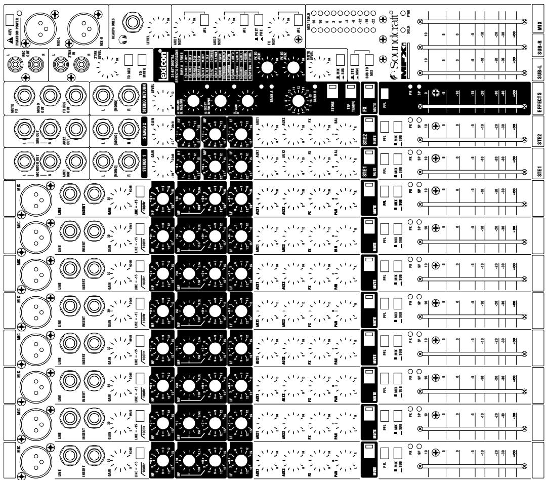
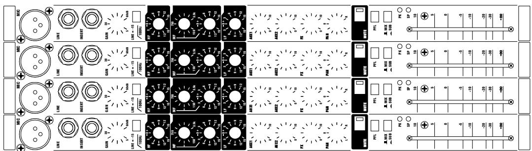

MPMi MARK-UP SHEETS
You may freely copy this page, and use it to record the settings used for particular applications/gigs.
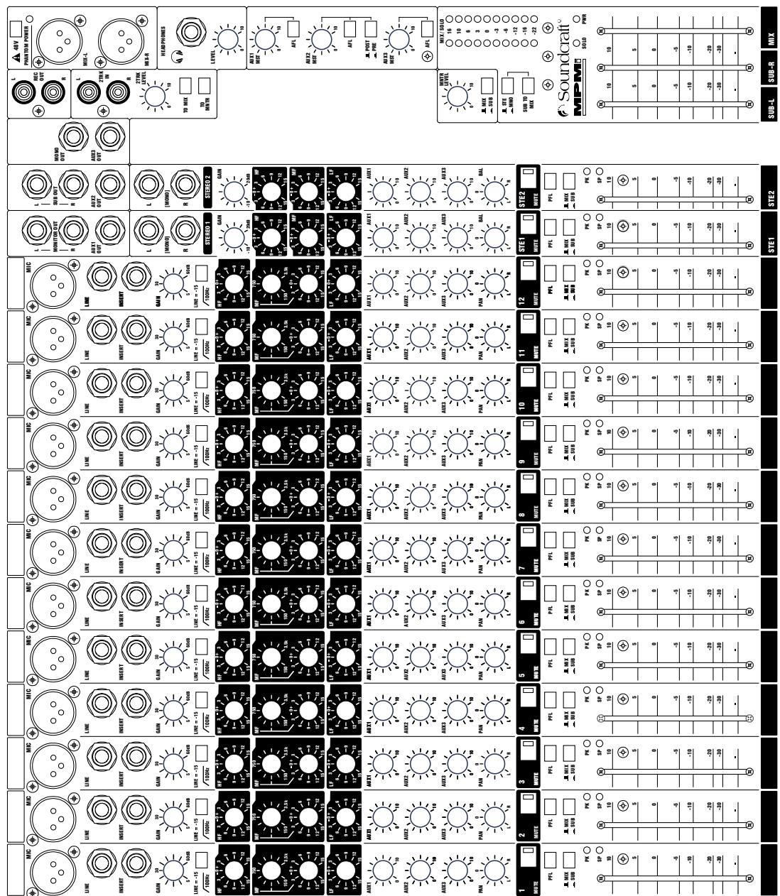
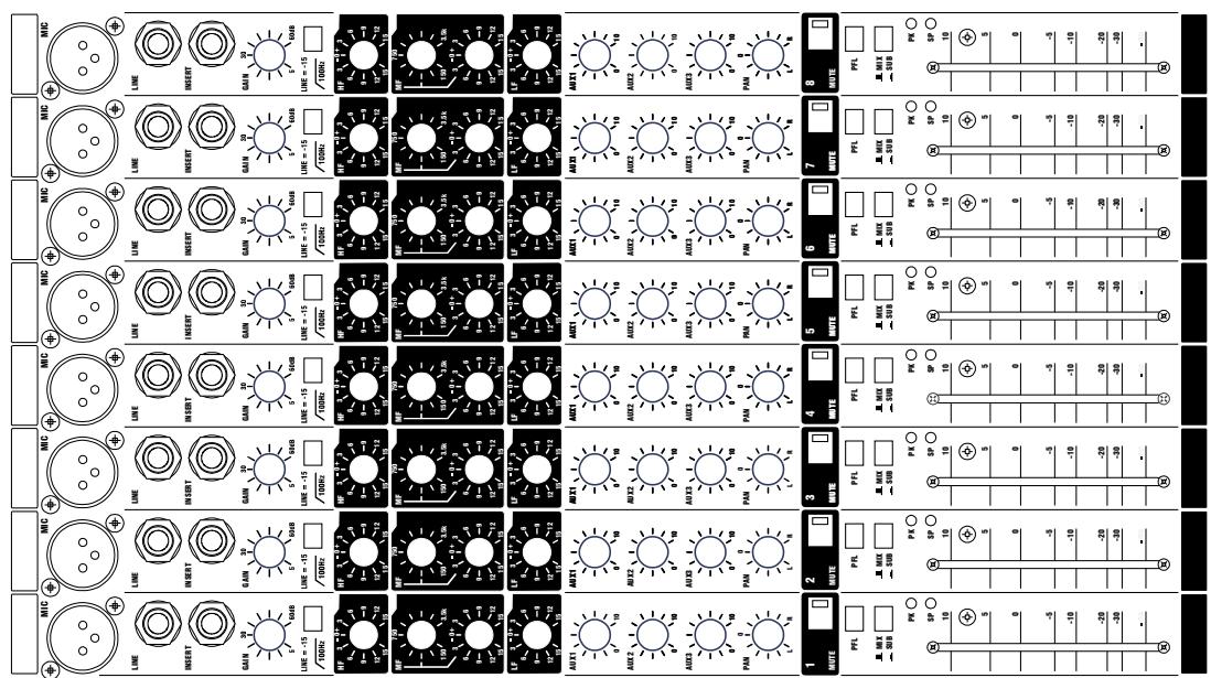
FITTING OPTIONAL RACK-MOUNT BRACKETS
The rack-mount kit is included with the MFXi12/2 and MPMi12/2.
For MFXi8/2 the rack-mount bracket kit is part number RW5765. This may also be used on the MFXi 20/2 and MPMi 20/2 for furniture mounting.
WARNING: ensure that the mixer is disconnected from the mains supply and all other equipment before fitting the rack-mounting brackets.
Undo and remove the screws at A and remove the side mouldings.
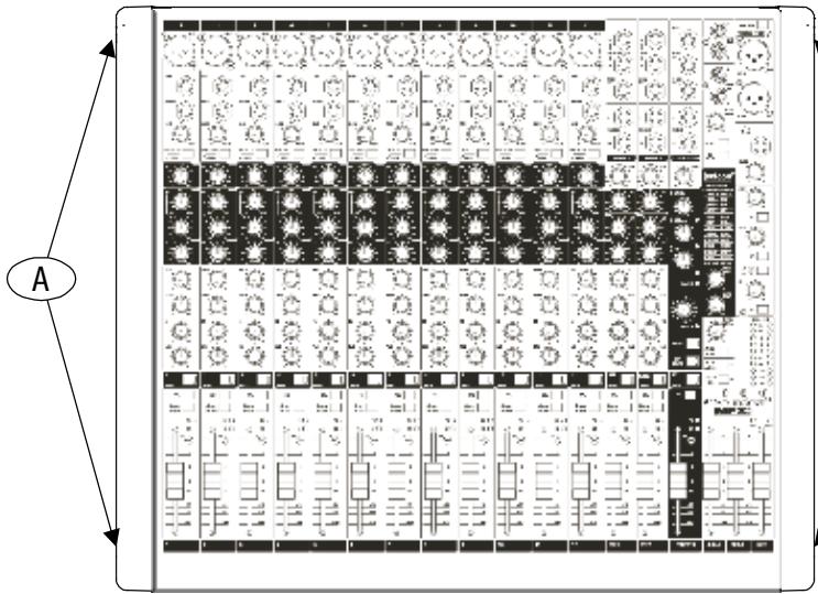
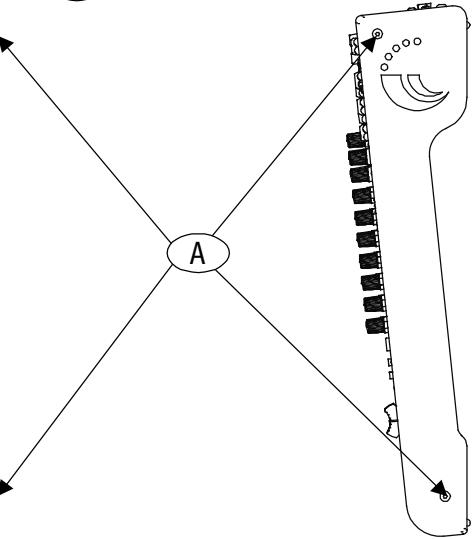
Remove the screw at point 1 , repeat on the other side of the mixer.
Attach the rack brackets to both sides of mixer at points 2 with the screws
removed at A and B1 above.

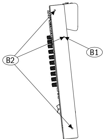
Keep the side mouldings in case you want to re-fit them at a later date.
Fitting the Extender Plate (MFXi8 ONLY)
The extender plate is fitted to the rackmounting bracket as shown below with M6 screws/cage nuts.
1 Attach captive rack nuts at points A.
2 Attach rack bolts through points B and into fitted rack nuts at points A. Tighten securely!
The console can now be fitted to a standard 19" rack. Note: the extender can be fitted to the left or right-hand side as required.
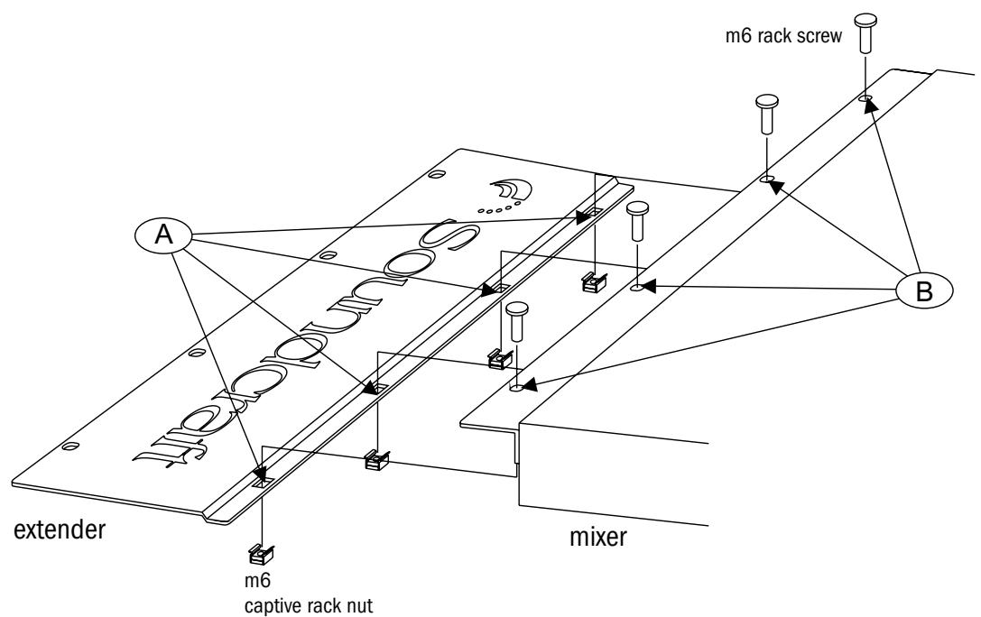
DIMENSIONS
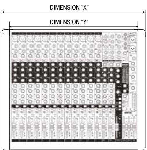
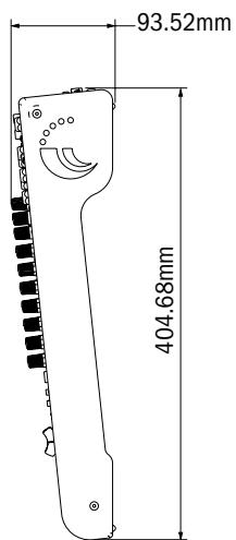
| DIMENSION “X” | DIMENSION “Y” | |
| MFXi8/2 | 383mm | 333mm |
| MFXi12/2 | 482mm | 432mm |
| MFXi20/2 | 688mm | 638mm |
APPLICATIONS
APPLICATION 1 - LIVE SOUND REINFORCEMENT
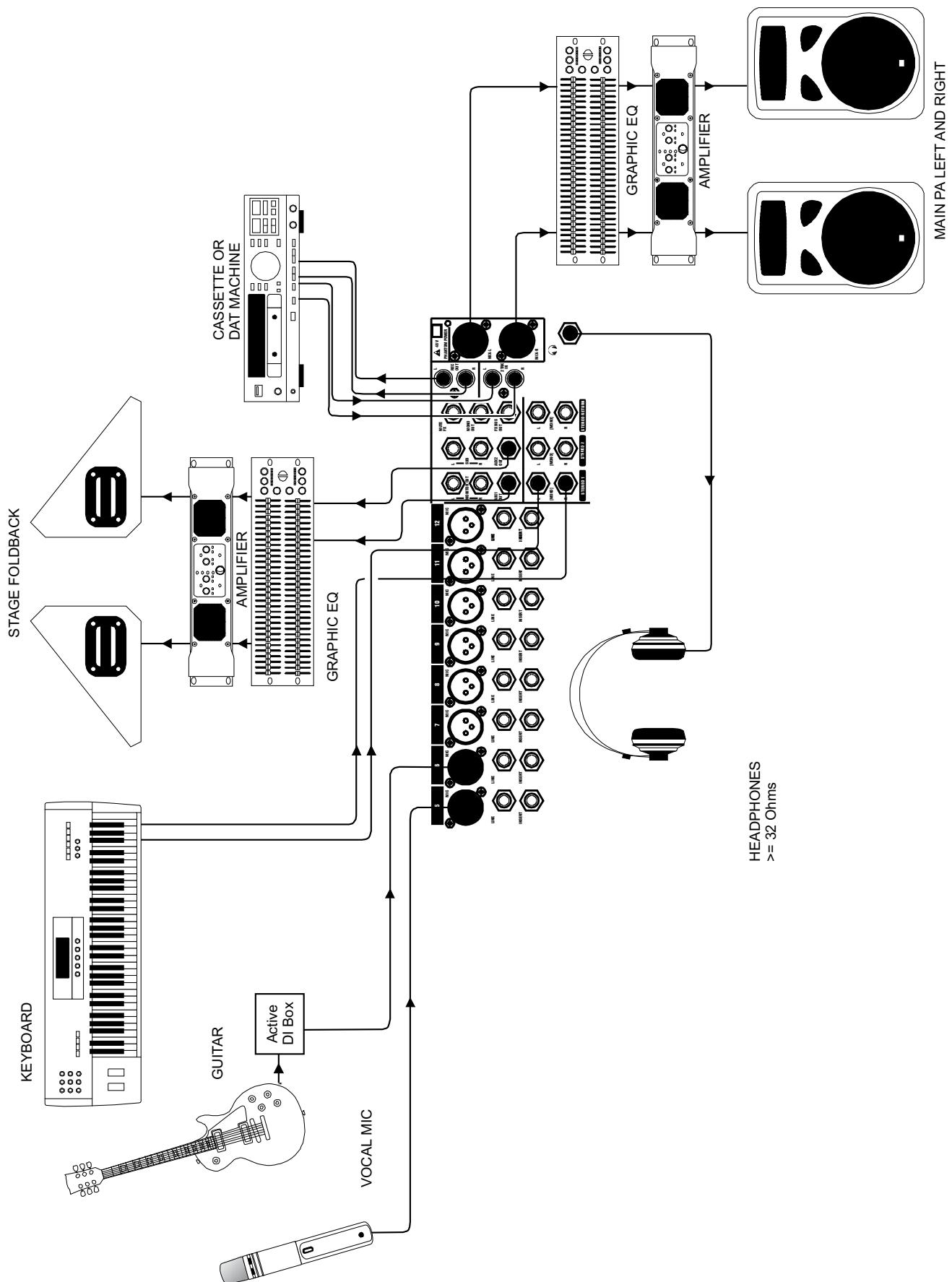
APPLICATION 2 - MULTISPEAKER APPLICATIONS
This configuration demonstrates how multiple speaker configurations can be driven by the MFXi.

APPLICATION 3 - PLACES OF WORSHIP
This configuration uses the Aux 2 output to drive an induction loop for the hard of hearing. Aux 1 output is used to generate foldback monitoring for the speaker/singer. The main outputs are used to drive the main speaker system. The record and playback connections are used to pass audio to and from a DAT machine or CDR.
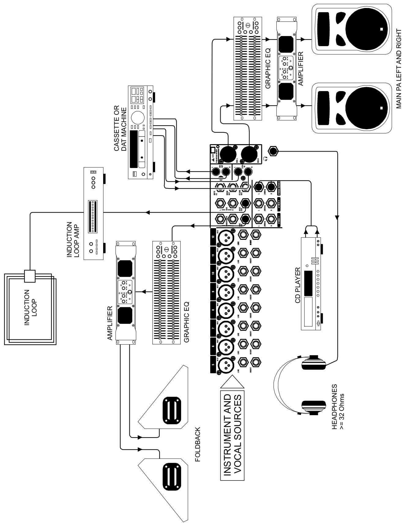
The insert points on channels 1-8 may be used to feed a multitrack recorder as shown (link the send and return signals). The Mix outputs are used for a preliminary stereo mix on a DAT recorder.
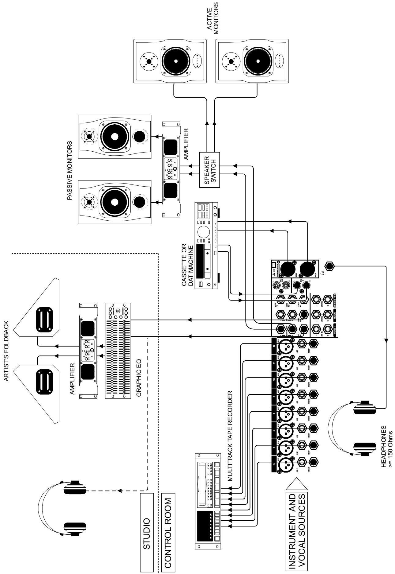
TYPICAL CONNECTING LEADS
Audio connectors used with Soundcraft consoles

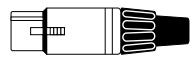
XLR
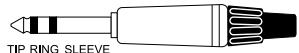
3-pole 14 " (A guage TRS) jack
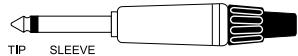
2-pole 14 " (A guage TS) jack

RCA phono
Balanced - Line Inputs, Mix L & R Outputs, Stereo Inputs, Auxiliary Outputs


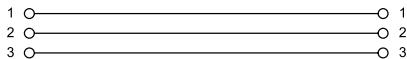


Unbalanced - Direct Output, Monitor Output, Stereo Return Inputs


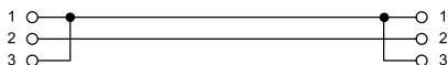
Insert Cables - Mono Inserts
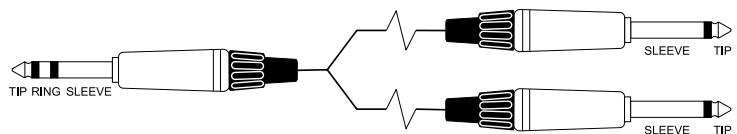
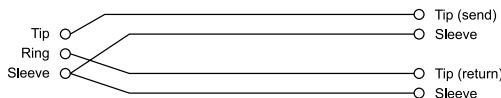
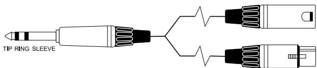

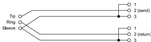
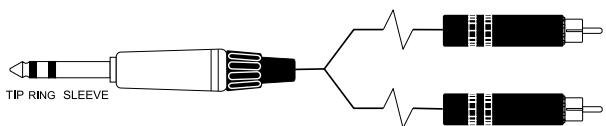

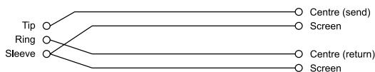
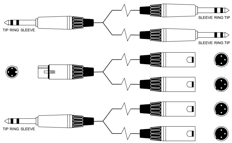
'Y' Cables (Balanced)
Where used ... Aux, Mix outputs
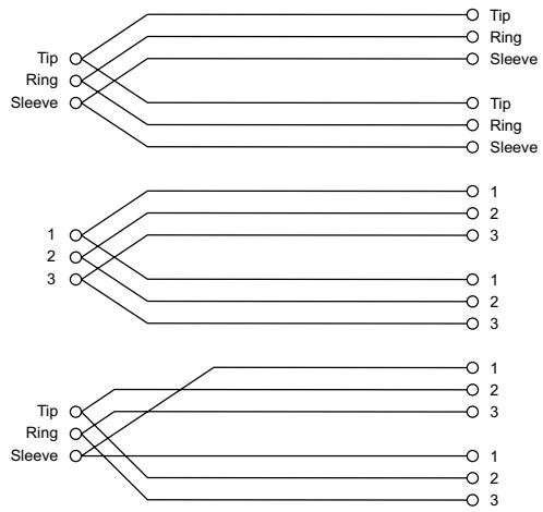
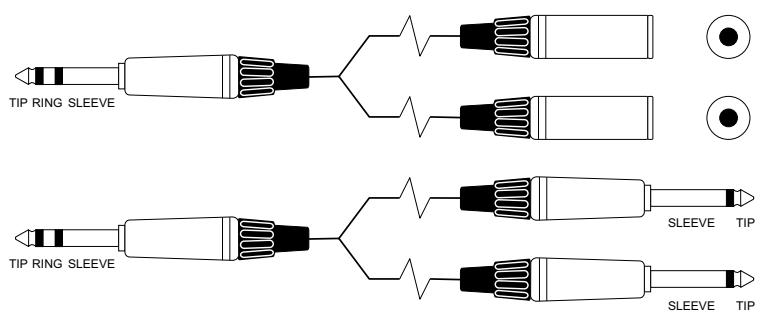
Headphone Separator
Note: for every doubling of headphones the load impedance is halved. Do not go below 32 Ohms.
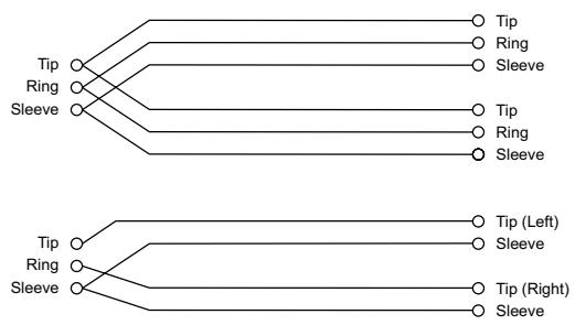

Y' Cables (Unbalanced)

GLOSSARY
| AFL | After-fade listen: a function that allows the operator to monitor the post-fade signal in a channel independently of the main mix. |
| Auxiliary send | An output from the console comprising a mix of signals from channels derived independently of the main stereo mix. |
| Balance | The relative levels of the left and right channels of a stereo signal. |
| Balanced | A method of audio connection which ‘balances’ the wanted signal between two wires, these wires also have a screen which carries no signal. Any interference is picked up equally by the two wires, which results in cancellation of the unwanted signal. In this guide, the term can refer to various circuit architectures. Connection details are given in relevant sections. |
| Clipping | The onset of severe distortion in the signal path, usually caused by the peak signal voltage being limited by the circuit's power supply voltage. |
| DAT | Digital Audio Tape, a cassette-based digital recording format. |
| dB (decibel) | A ratio of two voltages or signal levels, expressed by the equation dB=20Log10 (V1/V2). Adding the suffix ‘u’ denotes the ratio is relative to 0.775V RMS. |
| DI(direct injection)/DI | Box The practice of connecting an electric musical instrument directly to the input of the mixing console, rather than to an amplifier and loudspeaker which is covered by a microphone feeding the console. |
| Equaliser | A device that allows the boosting or cutting of selected bands of frequencies in the signal path. |
| Fader | A linear control providing level adjustment. |
| Feedback | The ‘howling’ sound caused by bringing a microphone too close to a loudspeaker driven from its amplified signal. |
| Foldback | A feed sent back to the artistes via loudspeakers or headphones to enable them to monitor the sounds they are producing. |
| Frequency response | The variation in gain of a device with frequency. |
| Gain | The amount of amplication in level of the signal. |
| Headroom | The available signal range above the nominal level before clipping occurs. |
| Impedance balancing | A technique used on unbalanced outputs to minimise the effect of hum and interference when connecting to external balanced inputs. |
| Insert | A break point in the signal path to allow the connection of external devices, for instance signal processors or other mixers at line level signals. Nominal levels can be anywhere between 0dBu to +6dBu, usually coming from a low impedance source. |
| Pan (pot) | Abbreviation of ‘panorama’: controls the levels sent to left and right outputs. |
| Peaking | The point at which a signal rises to its maximum instantaneous level, before falling back down again. It can also describe an equaliser response curve affecting only a band of frequencies, (like on a graphic equaliser), “peaking” at the centre of that band. |
| Peak LED | A visual indication of the signal peaking just before the onset of clipping, which will distort the signal. |
| PFL | Pre-fade listen: a function that allows the operator to monitor the pre-fade signal in a channel independently of the main mix. |
| Phase | A term used to describe the relationship of two audio signals. In-phase signals reinforce each other, out-of-phase signals result in cancellation. Phase is a measurement of relative displacement between two waves of identical frequency. |
| Polarity | A term used to describe the orientation of the positive and negative poles of an audio connection. Normally connections are made with positive to positive, negative to negative. If this is reversed, the result will be out-of-phase signals (see ‘phase’ above). |
| Post-fade | The point in the signal path after a fader and therefore affected by the fader position. |
| Pre-fade | The point in the signal path before a fader, and therefore unaffected by the fader position. |
| Rolloff | A fall in gain at the extremes of the frequency response. |
| Shelving | An equaliser response affecting all frequencies above or below the break frequency i.e. a highpass or lowpass derived response. |
| Solo | An almost generic term used to describe PFL or AFL functions. |
| Spill | Acoustic interference from other sources. |
| Transient | A momentary rise in the signal level. |
| Unbalanced | A method of audio connection which uses a single wire and the cable screen as the signal return. This method does not provide the noise immunity of a balanced input (see above). |
| +48V | The phantom power supply, available at the channel mic inputs, for condenser microphones and active DI boxes. |
WARRANTY
1 Soundcraft is a trading division of Harman International Industries Ltd .
End User means the person who first puts the equipment into regular operation.
Dealer means the person other than Soundcraft (if any) from whom the End User purchased the Equipment, provided such a person is authorised for this purpose by Soundcraft or its accredited Distributor. Equipment means the equipment supplied with this manual.
2 If within the period of twelve months from the date of delivery of the Equipment to the End User it shall prove defective by reason only of faulty materials and/or workmanship to such an extent that the effectiveness and/or usability thereof is materially affected the Equipment or the defective component should be returned to the Dealer or to Soundcraft and subject to the following conditions the Dealer or Soundcraft will repair or replace the defective components. Any components replaced will become the property of Soundcraft.
3 Any Equipment or component returned will be at the risk of the End User whilst in transit (both to and from the Dealer or Soundcraft) and postage must be prepaid.
4 This warranty shall only be valid if:
a) the Equipment has been properly installed in accordance with instructions contained in Soundcraft's manual; and
b) the End User has notified Soundcraft or the Dealer within 14 days of the defect appearing; and
c) no persons other than authorised representatives of Soundcraft or the Dealer have effected any replacement of parts maintenance adjustments or repairs to the Equipment; and
d) the End User has used the Equipment only for such purposes as Soundcraft recommends, with only such operating supplies as meet Soundcraft's specifications and otherwise in all respects in accordance with Soundcraft's recommendations.
5 Defects arising as a result of the following are not covered by this Warranty: faulty or negligent handling, chemical or electro-chemical or electrical influences, accidental damage, Acts of God, neglect, deficiency in electrical power, air-conditioning or humidity control.
6 The benefit of this Warranty may not be assigned by the End User.
7 End Users who are consumers should note their rights under this Warranty are in addition to and do not affect any other rights to which they may be entitled against the seller of the Equipment.

by HARMAN
SOUNDCRAFT
A Division of Harman International Industries Ltd
Cranborne House, Cranborne Road,
Potters Bar, Herts, EN6 3JN, UK
Tel +44 (0) 1707 665000
Fax: +44 (0) 1707660742
Email: soundcraft@harman.com
SOUNDCRAFT USA
8500 Balboa Boulevard
Northridge
CA 91329 USA
Tel: +1-818-920-3212
Fax: +1-818-920-3208
Toll Free: 888-251-8352
Email: soundcraft-usa@harman.com