
AMM 10 - Wireless Microphone System AKG - Free user manual and instructions
Find the device manual for free AMM 10 AKG in PDF.

| Product Type | Modular wireless microphone system |
| Brand | AKG |
| Model | AMM 10 |
| Dimensions (module) | 50 x 50 x 50 mm |
| Weight (module) | Approximately 60 g to 70 g (depending on module) |
| Weight (PSU 10 power supply) | Approximately 200 g |
| Power supply | PSU 10: ±12 V DC, max. 250 mA |
| Maximum consumption (module) | ±16 mA to ±50 mA (depending on module) |
| Maximum number of modules | 10 active modules (limited by power supply) |
| Maximum distance between modules | 100 m with CAT5 cable |
| Cable type | Shielded CAT5 cable, cross-section 0.12 mm² to 0.5 mm² |
| Connectors | XLR 3-pin, 3.5 mm jack, RCA (Cinch), USB Type A |
| Frequency range | 20 Hz to 30 kHz (depending on module) |
| Signal-to-noise ratio | 70 dB to 90 dB (depending on module) |
| Distortion factor | < 0.005% to < 0.1% (depending on module) |
| Ambient temperature range | 0 °C to +55 °C |
| Front panel material | Stainless steel |
| Maintenance and cleaning | Slightly damp cloth, never use abrasive products or solvents |
| Safety | Use in dry rooms, do not expose to weather, repair by authorized personnel |
| Spare parts and repairability | Opening and repair reserved for qualified technical personnel |
| Contents of the delivery (starter kit) | Input/output modules, PSU 10 power supply, mounting frames, screws |
Frequently Asked Questions - AMM 10 AKG
User questions about AMM 10 AKG
0 question about this device. Answer the ones you know or ask your own.
Ask a new question about this device
Download the instructions for your Wireless Microphone System in PDF format for free! Find your manual AMM 10 - AKG and take your electronic device back in hand. On this page are published all the documents necessary for the use of your device. AMM 10 by AKG.
USER MANUAL AMM 10 AKG
Please read the manual before using the equipement!
MODE D'EMPLOI 66
1 Safety and Environment. 35
Safety. 35
Environment 35
2 Description. 36
Introduction 36
Items supplied with starter kit 36
Optional Accessories 36
Summary 36
Modules 36
3 Installation and Connection 38
Fitting the modules 38
Connecting the modules 40
Preparing the cabling. 40
Wiring the modules 41
Connecting REC OUT 43
Connecting XLR OUT PAS. 44
Connecting the power supply 44
Connecting TRAFO IN 45
Connecting TRAFO OUT 46
Module wiring diagram 48
AMM 10 wiring diagram 48
4 Operation 49
MASTER CONTROL 49
D-MICIN 49
C-MIC IN 50
CD/PCIN 50
MP3/PCIN. 51
XLR OUT PAS. 51
XLR OUT ACT. 52
CONTROL OUT. 53
REC OUT 53
PSU10. 54
TRAFO IN. 54
TRAFO OUT 55
5 Cleaning. 56
6 Specifications 57
7 Troubleshooting 64
8 Copyright 65
1 Safety and Environment
Safety
- Do not expose the equipment to direct sunlight, excessive dust, moisture, rain, mechanical vibrations, or shock.
- Do not spill any liquids on the equipment or allow objects to fall inside through the ventilation slots.
- The equipment must only be used in dry rooms.
- The equipment must only be opened, serviced, and repaired by authorised personnel. The equipment contains no user-serviceable parts.
- If any solid object or liquid should get into the equipment, shut down the system immediately.
- Do not place the equipment near heat sources such as radiators, heating ducts, amplifiers, etc. and do not expose it to direct sunlight, excessive dust, moisture, rain, mechanical vibrations, or shock.
- To avoid hum or interference, route all audio lines, particularly those connected to the microphone inputs, away from power lines of any type. If you use cable ducts, be sure to use separate ducts for the audio lines.
- Clean the equipment with a moistened (not wet) cloth only. Be sure to disconnect the AC adapter from the power outlet before cleaning the equipment. Never use caustic or scouring cleaners or cleaning products containing alcohol or solvents since these may damage the enamel and plastic parts.
- Only use the equipment for the applications described in this manual. AKG cannot accept any liability for damages resulting from improper handling or misuse.

Risk of hearing loss!
If used in conjunction with headphones, this equipment can generate sound levels capable of causing permanent hearing loss. Therefore avoid excessive sound volumes (according to EN60065)
Environment

1) When the product reaches the end of its life, separate the housing, electronics and cables and dispose of all components in accordance with local waste disposal regulations.
2) The packaging can be recycled. Dispose of the packaging in a suitable collection system.
2 Description
Introduction
Thank you for purchasing an AKG product. This Manual contains important instructions for setting up and operating your equipment. Please take a few minutes to read the instructions below carefully before operating the equipment. Please keep the Manual for future reference. Have fun and impress your audience!
Items supplied with starter kit
Please check that the packaging contains all the components. If anything is missing, contact your AKG dealer at once.
- 1 x MIC/LINE input module (D-Mic IN)
- 1 x AUX input module (CD/PC IN)
- 1 x master output module (MASTER CONTROL) with balanced stereo output
- 1 x STEREO-LINE output module (XLR OUT PAS.)
- 1 x power supply PSU 10
- 4 x mounting frames
16x screws
Optional Accessories
For optional accessories, refer to the current AKG catalog or folder, or visit www.akg.com. Your dealer will be glad to help.
Summary
The AMM 10 multi-media connection system is a flexible, modular mixing system with a wide range of input and output modules. The individual modules are connected by a normal network cable (CAT 5) and can be fitted in standard mounting frames. Thanks to the plug-in design of the terminals, fitting the modules is very easy and requires little prior knowledge.
The modules can be fitted inside deep flush-mounted boxes or device boxes, cable ducts, floor boxes, etc., and can be combined with the cover frames of virtually every type of European switch.
Thanks to the flexible design, you can insert the required modules in the places where they are used. The system is designed to allow you to bridge long distances. This means that the input modules and the "master module" can be as far as 100 metres apart. Distances of up to 100 metres are also possible between the master module and the output modules.
Thanks to the flexible, modular system, the output signal can be tapped wherever you like. The maximum number of modules is limited only by the capacity of the power supply unit. Up to 10 modules can be connected with the supplied power supply unit PSU 10. Higher powered supply units are available on request.
Modules
MASTER CONTROL
The control and master output module is the heart of the system.
It receives incoming audio signals from all the input modules and, after amplification and tone adjustment, passes them to all the output modules.
This module must be connected to the system power supply (e.g. PSU 10).
D-MIC IN
The Mic/Line input module is a universal preamplifier module for connection of dynamic microphones or balanced line sources.
C-MIC IN
The C-Mic input module is a preamplifier module for connection of dynamic microphones and phantom-powered microphones.
The preamplifier is equipped with a limiter and configurable compressor.
CD/PCIN
The AUX / LINE IN module is a preamplifier module suitable for the connection of common, stationary AUX sound sources such as a CD player, tuner, cassette deck, etc., and also for portable audio devices such as MP3 players, Apple® iPod® and the like.
MP3/PC IN
The MP3 / USB POWER module is a preamplifier module suitable for connection of off-the-shelf MP3 players, Apple® iPod® or other portable audio devices via a jack socket. Battery power can be supplied to the connected device via a standard-compliant USB socket.
XLR OUT ACT.
The stereo line output module is an output module with electrically balanced stereo XLR output. It is used to connect e.g. power amplifiers, mixing desks and the like.
CONTROL
The headphone output module is an output module that displays the system output level with integrated headphone output.
REC OUT
The REC output module is an output driver module suitable for the connection of common, stationary recording equipment such as a CD recorder, cassette deck, etc., and also for portable recording equipment such as MP3 recorders, tape machines, etc.
XLR OUT PAS.
The stereo line output module is an output module with stereo XLR output (Line Out). It is used to connect e.g. power amplifiers, mixing desks and the like.
TRAFO IN
The TRAFO IN plug-in module can only be used in conjunction with the CD / PC IN module. The unbalanced inputs are kept potential-free by the isolating transformers.
TRAFO OUT
The TRAFO OUT plug-in module can only be used in conjunction with the AUX / LINE OUT module or the XLR OUT PAS. module. The outputs are kept potential-free and earth loops are effectively broken by the isolating transformers. Asymmetries and transient currents are also effectively prevented in this way.
PSU 10
Power is supplied by the PSU 10 power supply unit. Other power supply units not approved by us are not to be used!
3 Installation and Connection
Fitting the modules

RISK OF INJURY!
The devices must only be installed by authorised technicians.
Observe the following basic requirements prior to installation:
- Install the modules only in dry rooms.
- For installation use deep mounting boxes with an internal depth of at least 55mm .
- Clean any dust and other impurities from the mounting frames and mounting boxes. If necessary use a damp, but not wet, cloth.
The following criteria must be satisfied during installation:
- When installing, avoid proximity to parts under mains voltage.
- Use only shielded CAT5 cable.
It is permitted to use a CAT 5 cable with a conductor cross-section of not less than 0.12 mm² (AWG26) and not more than 0.5 mm² (AWG20).
- The PSU 10 power supply unit must be mounted directly adjacent to the control and master output module, as the operating voltage is supplied here.
- The optional REC OUT module must be installed one slot away from the control and master output module.
- Make sure that the shield and the drain wire do not touch any electronic components.

Assembly sequence
The assembly sequence is always the same, whether it is in a cavity wall box, a flush or surface-mounted box, a cable duct or a desktop case.
Make sure that the CAT5 cable has been correctly laid as far as the installation location.
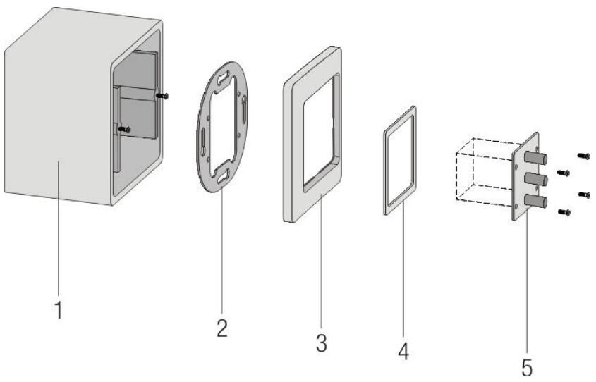
Figure 1: Description of individual parts
1 = Mounting box 4 = Intermediate frame
2 = Mounting frame 5 = Module (schematic)
3 = Cover frame
1) Screw the mounting frame onto the mounting box.
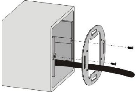
Figure 2: Fastening the mounting frame
2) Place the cover frame and intermediate frame over the mounting frame and pass the CAT5 cable through these frames.
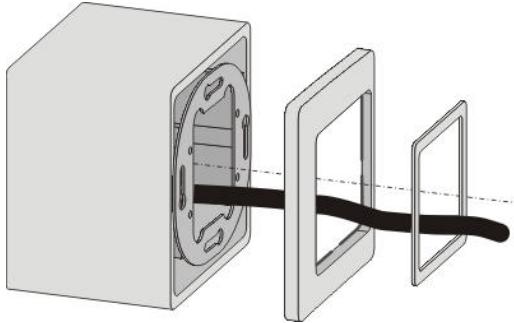
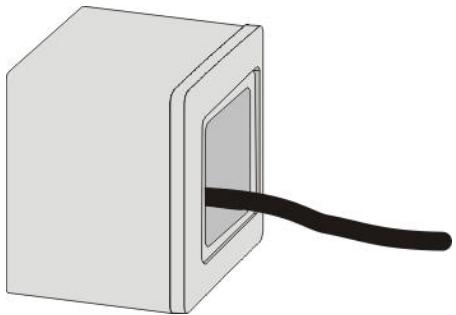
Figure 3: Fitting the cover frame and intermediate frame
Figure 4: All frames assembled
3) Connect the module as described under Connecting the modules (Page 40).
4) Align the module and screw it tight.

RISK OF DAMAGE!
Guide the module carefully and precisely into the mounting box. Make sure that the metal drain wire does not touch any electronic components and that none of the wires gets trapped or their insulation damaged.
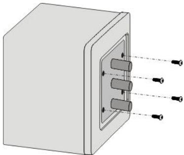
Figure 5: Fastening a module
Connecting the modules
Preparing the cabling
Once you have fitted all the necessary mounting boxes and laid the CAT5 cable, you can start installing the modules.

RISK OF INJURY!
The PSU 10 power supply unit must be connected last.
This module may only be installed by qualified technicians, observing relevant technical regulations and VDE directives.
Connection of the protective earth (PE) conductor is obligatory.
Remember that the PSU 10 power supply unit and the optional REC OUT module have to be next to each other due to the length of the connecting cable.

CABLE LENGTH
Before cutting the CAT5 cable, remember to leave enough length in reserve.
Installing in cable ducts:
The cable should project by approx. 20~cm from the cable duct so that the module can be connected easily. A certain amount of cable can be left in reserve in case you want to move the frames in the cable ducts later on.
Flush mounting:
Insert the modules without applying much force. When choosing the cable length make sure there is enough space in the box for the installed module.

RISK OF DAMAGE!
Too much spare cable in the flush-mounted box can damage the cable or the circuit board. Pressing the circuit board against a cable may damage or even cut through it. Shorten the cable if necessary.
Stripping the CAT cable
1) Score the CAT cable about 5cm from the end and remove the sheath. Take care that you do not cut into or through the individual wires.
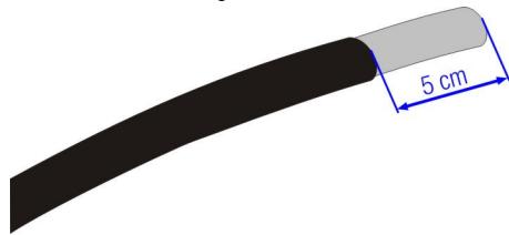
Figure 6: De-sheathing the CAT cable
2) Remove the shielding. Take a side cutter and cut into the shielding. The shield can now be removed so that the four wire pairs and the drain wire become visible.
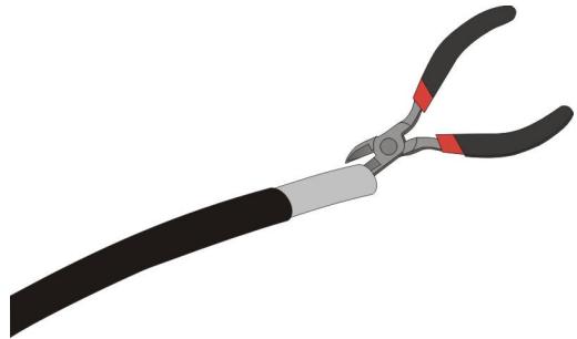
Figure 7: Removing the shielding

NOTE
REMOVING THE SHIELDING
Ease a side cutter carefully under the shielding and cut into it a little. After that it can be loosened easily.

NOTE
EARTH POTENTIAL
Be very careful that you do not cut the metal drain wire of the CAT cable as this is needed for earth potential!
Wiring the modules
To avoid confusion, sort the wires into the correct colour sequence. All modules, if attached to the "bus", are always connected in the same sequence:

Figure 8: Wire connection scheme
1 = White-green
2 = Green
3 = White-orange
4 = Blue
5 = White-blue
6 = Orange
7 = White-brown
8 = Brown
9 = Drain wire
Connecting the modules
1) Strip approx. 6 mm of insulation from the individual wires. Use a suitable tool for this purpose (e.g. stripping pliers)
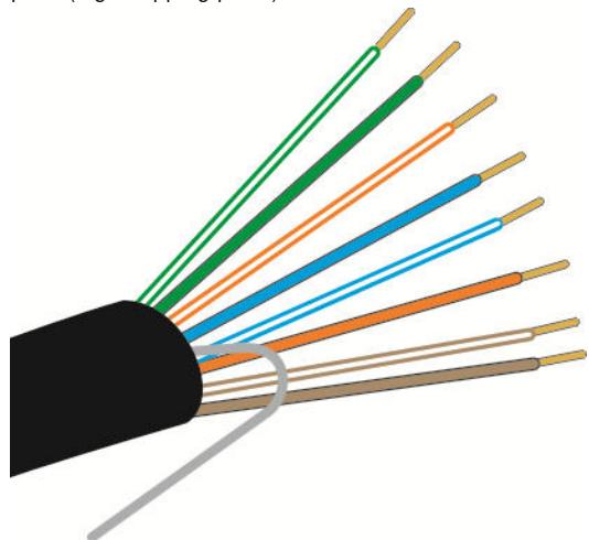
Figure 9: Conductors in correct sequence
2) Arrange the wires in the correct sequence; see connection scheme above.
3) Insert the wires one after the other in the terminal. Push the wires into the terminal until you feel a slight resistance. Using flat-nose pliers will make this easier. Make sure the stripped portion of the wire is not too long and does not project from the terminal. Shorten the core if necessary.
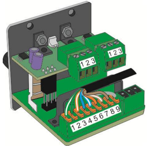
Figure 10: Connecting the wires
4) Fasten the CAT cable to the adjacent retainer with a cable tie. The strain relief prevents the wires from being torn out of the terminal if the cable is pulled.
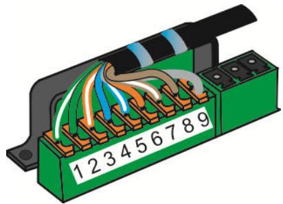
Figure 11: Strain relief of the CAT cable
5) If the connected module is not the last module in the series, insert the further portion of CAT5 cable into the second terminal of the correct socket in the same way.
6) The last module does not require any termination or similar device.
7) Install the module in the mounting box. Follow the instructions under Fitting the modules (Page 38)

DETACHING INDIVIDUAL WIRES
Place a thin object (e.g. ballpoint pen) in the small pit in the middle of the orange lever to prevent slipping. Press on the orange part of the connector and the wire can be pulled out with a small amount of resistance.
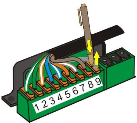
Figure 12: Detaching the wires
Connecting REC OUT
The AUX / LINE OUT module must be installed one slot away from the MASTER CONTROL, as the two modules are connected to one another via a separate cable.
The connectors of this cable are mechanically coded and so cannot be connected the wrong way round. Use only the cable included with the REC module to connect this module.
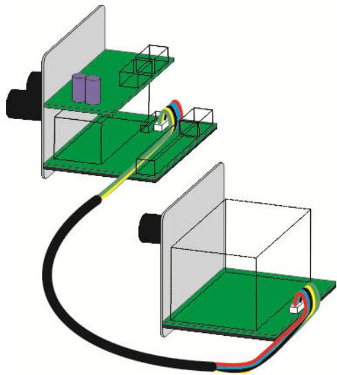
Figure 13: Connecting RECORD to MASTER CONTROL
Connect the cable to the special connectors provided for that purpose (small white terminal strip).
Connecting XLR OUT PAS.
The passive line output module LINE OUT (PASSIVE) is connected to the MASTER CONTROL module. It can only be used once in the system.
The LINE OUT (PASSIVE) module takes the electrically balanced output signal and uses it to drive power amplifiers, mixing desks or similar equipment. The volume and tone are controlled by the MASTER CONTROL. The level also depends on the setting of the input module that is used.
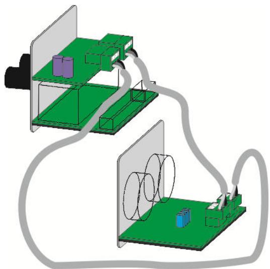
Figure 14: Connecting XLR-OUT to MASTER CONTROL
The terminals of the LINE OUT module and the MASTER CONTROL module are coded so that the two channels, left and right, cannot be confused.
Connecting the power supply

ATTENTION
RISK OF INJURY!
The PSU 10 power supply unit must be connected last.
This module may only be installed by qualified technicians, observing relevant technical regulations and VDE directives.
Connection of the protective earth (PE) conductor is obligatory.
The power supply connector is mechanically coded and can only be connected to the socket of the MASTER CONTROL. Because of the cable, the power supply unit must be mounted directly adjacent to the MASTER CONTROL.
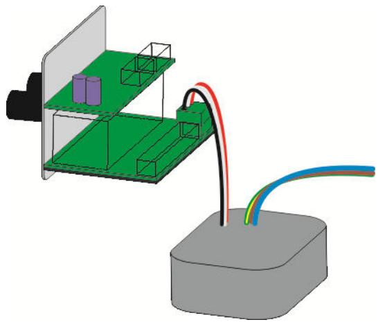
Figure 15: Connecting the power supply to MASTER CONTROL
Connecting TRAFO IN
The TRAFO IN plug-in module can only be used in conjunction with the AUX/LINE IN module.
You will need:
- TRAFO IN module and AUX/LINE IN module
- Supplied stainless steel cheese-head screw M3x5
- Size 2 Allen key
1) Undo the two screws on the underside of the AUX/LINE IN module. These screws fasten the black cover plate on the underside and the metal strain relief clip on the upper side.
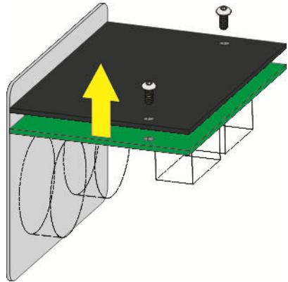
Figure 16: Unscrewing the base plate
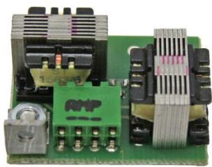
2) Remove the four blue jumpers from the top side of the circuit board and mount the transformer module in their place.
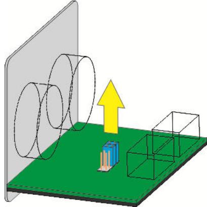
Figure 17: Removing jumpers

NOTE
Jumpers
After removing the jumpers, keep them in a safe place in case you want to remove the TRAFO IN module in the future. In that case, put the four blue jumpers back in their original position.
3) Fit the TRAFO IN module carefully.
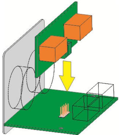
Figure 18: Mounting the transformer

RISK OF DAMAGE!
When fitting the module, take care to ensure that none of the pins of the connector becomes bent.
4) Screw the transformer module in place with the screw supplied.
5) Attach the cover plate together with the strain relief clip.
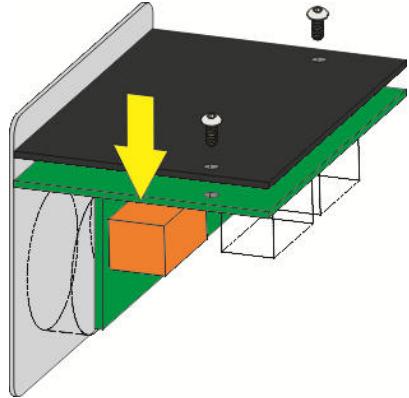
Figure 19: Screwing on the base plate.
Connecting TRAFO OUT
The TRAFO OUT plug-in module can only be used in conjunction with the AUX/LINE OUT module or the LINE OUT (ACTIVE) module or the LINE OUT (PASSIVE) module.
You will need:
- TRAFO OUT module and AUX/LINE OUT module or LINE OUT (ACTIVE) module or LINE OUT (PASSIVE) module
- Two supplied stainless steel cheese-head screws M3x5
Size 2 Allen key
1) Undo the two screws on the underside of the AUX/LINE OUT or LINE OUT module. These screws fasten the black cover plate on the underside and the metal strain relief clip on the upper side.
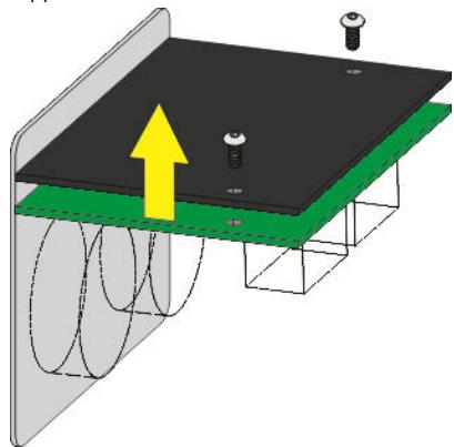
Figure 20: Unscrewing the base plate
2) Remove the four blue jumpers from the upper side of the circuit board and mount the transformer module in their place.
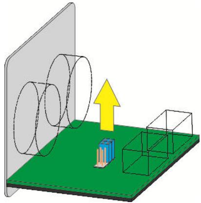
Figure 21: Removing jumpers

NOTE
Jumpers
After removing the jumpers, keep them in a safe place in case you want to remove the TRAFO OUT module in the future. In that case, put the four blue jumpers back in their original position.
3) Fit the TRAFO OUT module carefully.
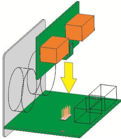
Figure 22: Mounting the transformer

ATTENTION
RISK OF DAMAGE!
When fitting the module, take care to ensure that none of the pins of the connector becomes bent.
4) Screw the transformer module in place with the screws supplied.
5) Attach the cover plate together with the strain relief clip.
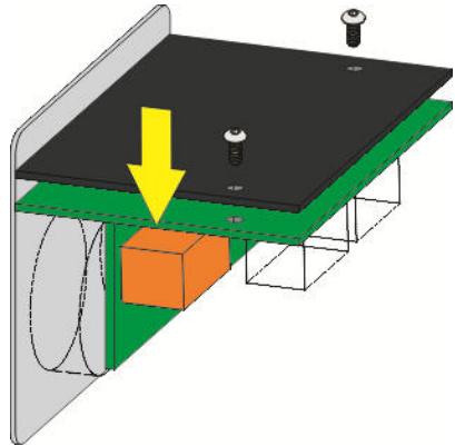
Figure 23: Screwing on the base plate.
Module wiring diagram
The wiring diagram provides information about the design and operating method of the individual modules of your AMM 10 multi-media connection system and shows how to wire them to one another correctly.
AMM 10 wiring diagram
This diagram illustrates one of the many ways of setting up a multi-media system in a room using the AMM 10. However, you can be as creative as you like in designing a multi-media connection tailored precisely to your needs.

NOTE
WIRING DIAGRAMS
The wiring diagrams can be found in the appendix at the end of the document.
4 Operation
MASTER CONTROL
The MASTER CONTROL module is connected to the PSU 10 power supply. It supplies power to the REC OUT recording output module.
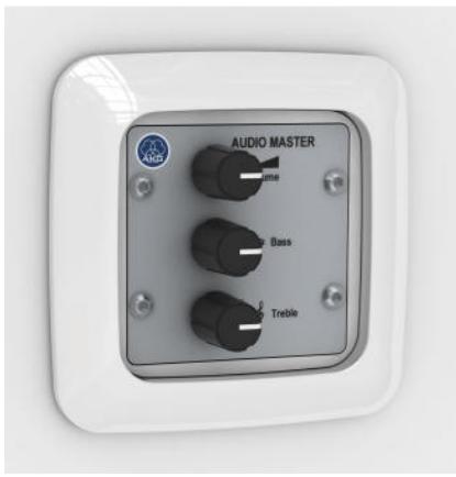
The front panel of the MASTER CONTROL has volume, bass and treble controls. How you set these affects all output modules and the CONTROL OUT module, but not the REC OUT record module.
Maximum number within the AMM 10 system:
Only one MASTER CONTROL can be used. The system must include this module.
D-MIC IN
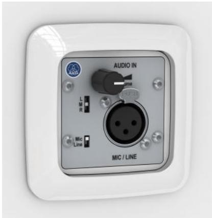
The front panel contains the volume control and the XLR input socket.
The "Mic / Line" slide switch is used to select an input sensitivity of -60dBu (Mic) or +/-0dBu (Line). Another slide switch is used to allocate the signal to the left (L) or right (R) stereo channel, or both channels simultaneously in mono operation (M).
Both slide switches are set back from the surface of the panel to protect against accidental switching. They can only be operated with a pointed object, such as a ballpoint pen.
Maximum number within the AMM 10 system:
Up to 10 MIC/LINE modules can be used, provided the power supply is adequate.
C-MIC IN
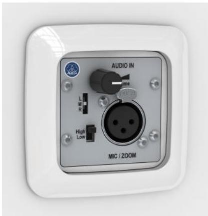
The preamplifier of the MIC/ZOOM module is equipped with a limiter and a configurable compressor. The limiter ensures a uniform maximum volume, while the compressor largely compensates for different mouth-to-mic distances or varying loudness of speech. The compressor function can be configured with jumpers prior to installation.
The front panel contains the volume control and the XLR input socket.
The "High / Low" slide switch is used to select an input sensitivity of -60dBu (High) or -40dBu (Low). Another slide switch is used to allocate the signal to the left (L) or right (R) stereo channel, or both channels simultaneously in mono operation (M).
Both slide switches are set back from the surface of the panel to protect against accidental switching. They can only be operated with a pointed object, such as a ballpoint pen.
Maximum number within the AMM 10 system:
Up to 10 MIC/ZOOM modules can be used, provided the power supply is adequate.
CD / PC IN
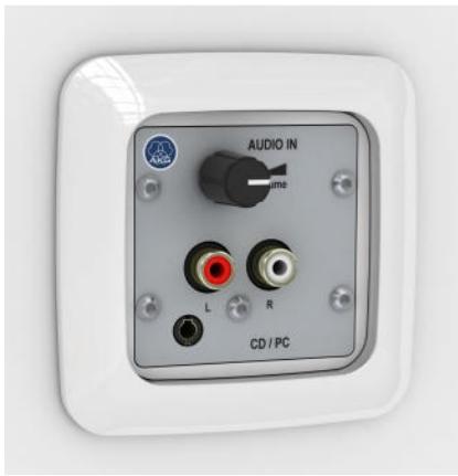
The AUX/LINE-IN module has two stereo phono sockets (L, R) and a 3.5mm stereo jack input. It also features a volume control.
Maximum number within the AMM 10 system:
Up to 10 AUX/LINE modules can be used, provided the power supply is adequate.

NOTE
EARTH LOOP
Connecting mains-powered audio sources with unbalanced outputs is often problematic, as an earth loop may be formed via the equipment's earth wire, antenna or similar.
If you want to use audio sources connected to earth, such as a PC, notebook, video recorder, tuner or similar with AUX/LINE-IN, we strongly recommend that you use the TRAFO IN (special accessory) (see "TRAFO IN" Page 54) plug-in module. This input transformer effectively breaks the earth loop.
MP3/PC IN
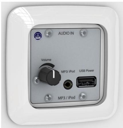
The front panel contains a volume control, a jack socket and a USB socket. This allows you to connect an MP3 player or Apple® iPod®.
Depending on its functionality, the connected device is supplied with battery-saving power, or the rechargeable battery is charged, via the USB socket. The audio signal from the playback device is fed into the 3.5mm stereo jack socket.

NOTE
USB SOCKET
The USB socket is used only to supply power, not to transfer data. The connected device must have an analogue audio output. Some devices, such as the Apple iPod Shuffle, cannot be charged simultaneously, i.e. during audio playback.
Maximum number within the AMM 10 system:
Up to 10 MP3 / USB POWER modules can be used, provided the power supply is adequate.
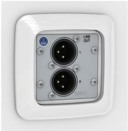
XLR OUT PAS.
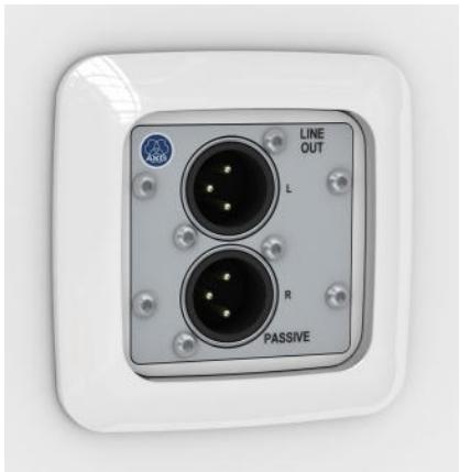
The LINE OUT (PASSIVE) module is an output module with a stereo XLR output (Line Out).
The volume and tone are controlled by the MASTER CONTROL (Page 49). The level also depends on the setting of the input module that is used. If several LINE OUT (PASSIVE) modules are used in the system, the settings of the MASTER CONTROL affect all of them equally.
Maximum number within the AMM 10 system:
Up to 10 LINE OUT (PASSIVE) modules can be used, provided the power supply is adequate.

NOTE
EARTH LOOP
With long transmission distances, where conditions may be further complicated by nearby electromagnetic influences, electrically balanced inputs and outputs are pushed to their technical limits. Under these unfavourable conditions, or for receiving equipment with unknown input circuits, we recommend using the TRAFO OUT (special accessory) (see "TRAFO OUT" Page 55) plug-in module. The transformer in this module effectively breaks any earth loops and prevents asymmetries and transient currents.
XLR OUT ACT.
The LINE OUT (ACTIVE) module is an output module with a stereo XLR output (Line Out).
The volume and tone are controlled by the MASTER CONTROL (Page 49). The level also depends on the setting of the input module that is used. If several LINE OUT (ACTIVE) modules are used in the system, the settings of the MASTER CONTROL affect all of them equally.
Maximum number within the AMM 10 system:
Up to 10 LINE OUT (ACTIVE) modules can be used, provided the power supply is adequate.

NOTE
EARTH LOOP
With long transmission distances, where conditions may be further complicated by nearby electromagnetic influences, electrically balanced inputs and outputs are pushed to their technical limits. Under these unfavourable conditions, or for receiving equipment with unknown input circuits, we recommend using the TRAFO OUT (special accessory) (see "TRAFO OUT" Page 55) plug-in module. The transformer in this module effectively breaks any earth loops and prevents asymmetries and transient currents.
CONTROL OUT
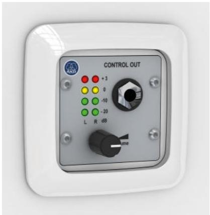
The CONTROL OUT module is an output module with a headphone socket.
Use of this output module is especially recommended to help inexperienced operating personnel set levels. The result can be acoustically checked via the headphone output, unless the audio is played back in the same room anyway.
The front panel contains a volume control and a 6.3 mm headphone jack socket. In addition, 8 LEDs indicate the current signal level on both stereo channels.
Maximum number within the AMM 10 system:
Up to 10 CONTROL OUT modules can be used, provided the power supply is adequate.
REC OUT
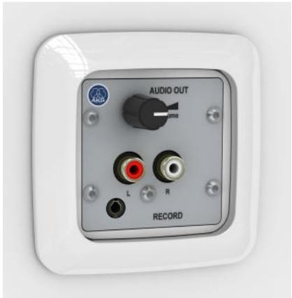
The front panel of the AUX/LINE OUT output module has two stereo phono sockets (L, R) and a 3.5mm stereo output jack socket. The recording level can be set via the volume control. This is dependent on the input controls of the input modules, but independent of the master volume setting.
As a special feature, the AUX/LINE OUT module has a pre-attached connection cable which connects this module to the MASTER CONTROL. Therefore, AUX/LINE OUT cannot be more than one slot away from the MASTER CONTROL.
Maximum number within the AMM 10 system:
Only one AUX/LINE OUT module can be used.

NOTE
EARTH LOOP
Connecting mains-powered recording devices with unbalanced outputs is often problematic, as an earth loop may be formed via the equipment's earth wire, antenna or similar. If you want to use recording devices connected to earth, such as a PC, notebook or similar with the REC output module, we strongly recommend that you use the TRAFO OUT (special accessory) (see "TRAFO OUT" Page 55) plug-in module. This input transformer effectively breaks the earth loop.
PSU10
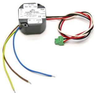
Power is supplied by the PSU 10 power supply unit. It is an efficient switched-mode power supply. Special design features guarantee optimum voltage smoothing and hence adulterated sound quality.

ATTENTION
RISK OF INJURY!
Other power supply units not approved by us are not to be used!
Depending on the composition of your system, the PSU 10 can supply at least 10 active modules.

NOTE
POWER SUPPLY
When planning your system, calculate the overall power consumption based on the technical data of the individual modules. If your system exceeds the capacity of the PSU 10, please contact us directly for a solution.
Maximum number within the AMM 10 system:
Only one PSU 10 module can be used. The system must include this module. If necessary, the PSU 10 can be replaced with a higher-capacity power supply unit.
TRAFO IN
The TRAFO IN plug-in module can only be used in conjunction with the AUX/LINE IN module. The unbalanced inputs are kept potential-free by the isolating transformers.
TRAFO OUT
The TRAFO OUT plug-in module can only be used in conjunction with the AUX/LINE OUT module or the LINE OUT (ACTIVE) module or the LINE OUT (PASSIVE) module. The outputs are kept potential-free and earth loops are effectively broken by the isolating transformers. Asymmetries and transient currents are also effectively prevented in this way.
5 Cleaning
Unplug the power supply unit from the socket.
Clean the surface of the unit with a moistened (not wet) cloth.

ATTENTION
Never use caustic or scouring cleaners or cleaning agents containing alcohol or solvents, since these may damage the enamel and plastic parts.
6 Specifications
MASTER CONTROL
System input:
| Type: | Electrically balanced |
| Number | 2 (stereo) |
| Nominal level | -7 dBu |
| Overload resistance | 10 dBu |
| System output: | |
| Type: | Unbalanced |
| Number | 2 (stereo) |
| Nominal level | ± 0 dBu |
| Minimum load impedance | 100 Ohm (@ -3 dB) |
| T.H.D. | < 0.005 % (@ 1 kHz) |
| Frequency range | 20 Hz ... 30 kHz |
| Bass control cut-off frequency | 100 Hz |
| Treble control cut-off frequency | 10 kHz |
| Range of tone controls | ± 12 dB |
| Signal-to-noise ratio | 85 dB S/N |
| Power supply: | |
| Operating voltage | ± 12 V DC (± 10 %) |
| Power consumption max. | ± 37 mA |
| Terminals | Phoenix screw terminal block Type: MC1.5/3ST-3.81 |
| Cross-section min. | 0.14 mm² |
| Cross-section max. | 1.5 mm² |
| System cable connections: | |
| Type | Spring force terminal 2 x 9-pole |
| Conductor type | Rigid |
| Cross-section min. | 0.12 mm² / AWG 26 |
| Cross-section max. | 0.5 mm² / AWG 20 |
| Expansion connectors: | |
| Type (1) | 7-pole JST |
| Purpose (1) | Volume remote control module |
| Type (2) | 5-pole JST |
| Purpose (2) | REC OUT |
| Type (3) | 6-pole post connector |
| Purpose (3) | LINE L/R |
| General: | |
| Permitted ambient temp. | approx. 0°C ... +55°C |
| Dimensions (l x w x h) | 50 x 50 x 50 |
| Front | Stainless steel |
| Weight | approx. 70 g (including LINE L/R) |
D-MIC IN
Input:
| Type | Electrically balanced |
| Nominal level | -60 / ±0 dBu (switchable) |
| Overload resistance | 10 dB |
| Impedance | 15 kΩ (@ 1 kHz) |
| Terminals | XLR 3-pole female |
| System output: | |
| Type | Electrically balanced |
| Number | 2 (stereo) |
| Nominal level | -7 dBu |
| Minimum load impedance | 7.2 kΩ (@ -3 dB) |
| T.H.D. | < 0.05 % (@ 1 kHz) |
| Frequency range | 50 Hz ... 60 kHz |
| Signal-to-noise ratio | 70 dB S/N (±0 dBu) |
| 63 dB S/N (-60 dBu) | |
| Power supply: | |
| Operating voltage | ± 12 V DC (± 10 %) |
| Power consumption max. | ± 16 mA |
| System cable connections: | |
| Type | Spring force terminal 2 x 9-pole |
| Conductor type | Rigid |
| Cross-section min. | 0.12 mm² / AWG 26 |
| Cross-section max. | 0.5 mm² / AWG 20 |
| Expansion connectors: | |
| Type | 7-pole JST |
| Purpose | Volume remote control module |
| General: | |
| Permitted ambient temp. | approx. 0°C ... +55°C |
| Dimensions (l x w x h) | 50 x 50 x 50 |
| Front | Stainless steel |
| Weight | approx. 60 g |
C-MIC IN
Input:
| Type | Electrically balanced |
| Nominal level | -60 / -40 dBu (switchable) |
| Overload resistance | 18 dB (limiter) |
| Impedance | 15 kΩ (@ 1 kHz) |
| Phantom power | +24 V DC |
| Terminals | XLR 3-pole female |
| System output: | |
| Type | Electrically balanced |
| Number | 2 (stereo) |
| Nominal level | -7 dBu |
| Minimum load impedance | 7.2 kΩ (@ -3 db) |
| T.H.D. | < 0.05 % (@ 1kHz) |
| Frequency range | 20 Hz ... 30 kHz |
| Signal-to-noise ratio | 70 dB S/N (±0 dBu) |
| 63 dB S/N (-60 dBu) | |
| Power supply: | |
| Operating voltage | ± 12 V DC (± 10%) |
| Power consumption max. | ± 50 mA |
| System cable connections: | |
| Type | Spring force terminal 2 x 9-pole |
| Conductor type | Rigid |
| Cross-section min. | 0.12 mm² / AWG 26 |
| Cross-section max. | 0.5mm² / AWG 20 |
| Expansion connectors: | |
| Type | 7-pole JST |
| Purpose | Volume remote control module |
| General: | |
| Permitted ambient temp. | approx. 0°C ... +55°C |
| Dimensions (l x w x h) | 50 x 50 x 50 |
| Front | Stainless steel |
| Weight | approx. 60 g |
CD / PC IN
Input:
| Type | Unbalanced |
| Nominal level | ± 0dBu |
| Overload resistance | 10dB |
| Impedance | 20 kΩ (@ 1kHz) |
| Connector A | Stereo jack socket 3.5mm |
| Connector B | Stereo phono sockets (RCA) |
System output:
| Type | Electrically balanced |
| Number | 2 (stereo) |
| Nominal level | -7 dBu |
| Minimum load impedance | 7.2 kΩ (@ -3 dB) |
| T.H.D. | < 0.03% (@ 1kHz) |
| Frequency range | 40 Hz ... 50 kHz |
| Signal-to-noise ratio | > 70 dB S/N |
Power supply:
| Operating voltage | ± 12 V DC (± 10%) |
| Power consumption max. | ± 16 mA |
System cable connections:
| Type | Spring force terminal 2 x 9-pole |
| Conductor type | Rigid |
| Cross-section min. | 0.12 mm² / AWG 26 |
| Cross-section max. | 0.5 mm² / AWG 20 |
Expansion connectors:
| Type (1) | 7-pole JST |
| Purpose (1) | Volume remote control module |
| Type (2) | 8-pole post connector |
| Purpose (2) | TRAFO IN |
General:
| Permitted ambient temp. | approx. 0°C ... +55°C |
| Dimensions (l x w x h) | 50 x 50 x 50 |
| Front | Stainless steel |
| Weight | approx. 60 g |
MP3/PC IN
Input:
| Type | Unbalanced |
| Nominal level | ± 0dBu |
| Overload resistance | 10 dB |
| Impedance | 20 kΩ (@ 1kHz) |
| Connector | Stereo jack socket 3.5 mm |
Charging socket:
| Type | USB® Type A |
| Voltage | 5 V DC |
| Max. current | 100 mA, continuous short circuit proof |
System output:
| Type | Electrically balanced |
| Number | 2 (stereo) |
| Nominal level | -7 dBu |
| Minimum load impedance | 7.2 kΩ (@ -3 dB) |
| T.H.D. | < 0.03 % (@ 1 kHz) |
| Frequency range | 40 Hz ... 50 kHz |
| Signal-to-noise ratio | 70 dB S/N |
Power supply:
| Operating voltage | ± 12 V DC (± 10%) |
| Power consumption max. | ± 50 mA during charging |
| Power consumption typical | ± 25 mA |
| System cable connections: | |
| Type | Spring force terminal 2 x 9-pole |
| Conductor type | Rigid |
| Cross-section min. | 0.12 mm² / AWG 26 |
| Cross-section max. | 0.5 mm² / AWG 20 |
| Expansion connectors: | |
| Type | 7-pole JST |
| Purpose | Volume remote control module |
| General: | |
| Permitted ambient temp. | approx. 0°C ... +55°C |
| Dimensions (I x w x h) | 50 x 50 x 50 |
| Front | Stainless steel |
| Weight | approx. 60 g |
XLR OUT PAS.
Input:
| Type | Balanced |
| Number | 2 (stereo) |
| Nominal level | ± 0 dBu |
| Terminals | Phoenix screw terminal block type:MC1.5/3ST-3.81 |
| Cross-section min. | 0.14 mm² |
| Cross-section max. | 1.5 mm² |
| Output: | |
| Type | Balanced |
| Number | 2 (stereo) |
| Connector | 2 x XLR 3-pole male |
| Nominal level | ± 0 dBu |
| Expansion connectors: | |
| Type | 8-pole post connector |
| Purpose | Transformer OUT |
| General: | |
| Permitted ambient temp. | approx. 0°C ... +55°C |
| Front | Stainless steel |
| Weight | approx. 70 g |
XLR OUT ACT.
Output:
| Type | Electrically balanced |
| Number | 2 (stereo) |
| Connector | 2 x XLR 3-pole male |
| Nominal level | ± 0 dBu |
| Overload resistance | 15 dB |
| Minimum load impedance | 120 Ω (@ -3 dB) |
| T.H.D. | < 0.08 % (@ 1 kHz) |
| Frequency range | 40 Hz ... 50 kHz |
| Signal-to-noise ratio | > 75 dB S/N |
| Input: | |
| Type | Unbalanced |
| Number | 2 (stereo) |
| Nominal level | -7 dBu |
| Impedance | 10 kΩ (@ 1 kHz) |
| Power supply: | |
| Operating voltage | ± 12 V DC (± 10%) |
| Power consumption max. | ± 15 mA |
| System cable connections: | |
| Type | Spring force terminal 2 x 9-pole |
| Conductor type | Rigid |
| Cross-section min. | 0.12 mm² / AWG 26 |
| Cross-section max. | 0.5 mm² / AWG 20 |
| Expansion connectors: | |
| Type | 8-pole post connector |
| Purpose | Transformer OUT |
| General: | |
| Permitted ambient temp. | approx. 0°C ... +55°C |
| Front | Stainless steel |
| Weight | approx. 70 g |
CONTROL OUT
Output:
| Type | Unbalanced |
| Nominal level | ± 0 dBu |
| Overload resistance | 15 dB |
| Nominal terminal impedance | >32 Ω |
| T.H.D. | < 0.1% (@ 1kHz) |
| Frequency range | 40 Hz ... 20 kHz |
| Signal-to-noise ratio | >80 dB S/N |
| Terminals | Stereo jack socket 3.5mm |
| Level display: | |
| Display range | -20 ... +3 dB |
| Graduation | -20, -10, ±0, +3 dB |
| Number of channels | 2 (stereo) |
| System input: | |
| Type | Unbalanced |
| Number | 2 (stereo) |
| Nominal level | -7 dBu |
| Impedance | approx. 3 kΩ |
| Power supply: | |
| Operating voltage | ± 12 V DC (± 10%) |
| Power consumption max. | ± 30 mA |
| System cable connections: | |
| Type | Spring force terminal 2 x 9-pole |
| Conductor type | Rigid |
| Cross-section min. | 0.12mm² / AWG 26 |
| Cross-section max. | 0.5mm² / AWG 20 |
| Expansion connectors | -/- |
| General: | |
| Permitted ambient temp. | approx. 0°C ... +55°C |
| Front | Stainless steel |
| Weight | approx. 70 g |
REC OUT
Input:
| Type | Unbalanced |
| Number | 2 (stereo) |
| Nominal level | -7 dBu |
| Impedance | 10 kΩ (@ 1kHz) |
| Output: | |
| Type | Unbalanced |
| Number | 2 (stereo) |
| Nominal level | 0 dBu |
| Max. output level | 15 dB |
| Min. output level | 200 Ω (@ -3 dB) |
| T.H.D. | < 0.001% (@ 1 kHz) |
| Frequency range | 40 Hz ... 50 kHz |
| Signal-to-noise ratio | >90 dB S/N |
| Connector A | Stereo jack socket 3.5mm |
| Connector B | Stereo phono sockets (RCA) |
| Power supply: | |
| Operating voltage | ±12 V DC (±10%) |
| Power consumption max. | ±6 mA |
| Power supply connectors: | |
| Type | Pre-attached cable |
| Length | 20 cm |
| Plug | JST 5-pole |
| Expansion connectors: | |
| Type | 8-pole post connector |
| Purpose | Transformer OUT |
| General: | |
| Permitted ambient temp. | approx. 0°C ... +55°C |
| Front | Stainless steel |
| Weight | approx. 70 g |
PS10
Mains input:
| Mains voltage | 230 V AC typ. 184 ... 264 V range |
| Mains frequency | 47 ... 63Hz |
| Power rating | max 12 W |
| Fuse protection | Internal polyfuse |
| Terminals | Screw terminals for L / N / PE |
| Cross-section min. | 0.75 mm² |
| Cross-section max. | 1.5 mm² |
| Output: | |
| Output voltage | ± 12 V DC (± 3%) |
| Output current max. | ± 250 mA |
| Protective circuits | Continuously protected against short circuit and open circuit |
| Ripple | < 5 mV eff. |
| Terminals | Screw terminals for +12V / 0V / 0V / -12V |
| Cross-section min. | 0.14 mm² |
| Cross-section max. | 1.5 mm² |
| System cable connections | -/- |
General:
| Permitted ambient temp. | approx. 0°C ... +55°C |
| Front | Stainless steel |
| Weight | approx. 200 g |
TRAFO IN
Input:
| Type | Balanced |
| Number | 2 (stereo) |
| Nominal level | ± 0 dBu |
| Max. input level | + 10 dBu |
Output:
| Type | Transformer – balanced earth-free |
| Number | 2 (stereo) |
| Nominal level | ± 0 dBu |
| Minimum load impedance | 5 kΩ |
| T.H.D. | < 0.005% (@ 1 kHz) / ± 0 dBu |
| Frequency range | 10 Hz ... 100 kHz |
| Transformation ratio | 1:1 |
Terminals:
| Type | 8-pole post connector (socket) |
| General: | |
| Permitted ambient temp. | approx. 0°C ... +55°C |
| Weight | approx. 30 g |
TRAFO OUT
Input:
| Type | Balanced |
| Number | 2 (stereo) |
| Nominal level | ± 0 dBu |
| Max. input level | +10 dBu |
Output:
| Type | Transformer – balanced earth-free |
| Number | 2 (stereo) |
| Nominal level | ± 0 dBu |
| Minimum load impedance | 600 Ω |
| T.H.D. | < 0.01% (@ 1 kHz) / ± 0 dBu |
| Frequency range | 30 Hz ... 100 kHz |
| Transformation ratio | 1:1 |
Terminals:
| Type | 8-pole post connector (socket) |
| General: | |
| Permitted ambient temp. | approx. 0°C ... +55°C |
| Weight | approx. 30 g |
7 Troubleshooting

ATTENTION
RISK OF INJURY!
Only authorised service personnel may open the device for troubleshooting.
| Problem | Possible cause | Remedy |
| No sound | Plug of PSU 10 is not connected to MASTER CONTROL | Connect PSU 10 |
| Voltage at modules less than ± 10.9 V | Reduce cable length | |
| No earth potential, metal drain wire has been cut | Use new CAT5 cable | |
| Cable not properly connected | Connect bus cable correctly | |
| LINE OUT module is not connected to amplifier | Connect output module to amplifier | |
| Microphone or auxiliary device not connected | Connect microphone or auxiliary device to unit | |
| Selector switch on MIC/LINE or MIC/ZOOM is set to LINE input | Set selector switch to MIC | |
| Volume control set to minimum | Turn up volume control | |
| Phantom power is switched off | Switch on phantom power for condensor microphone | |
| Distorted signal reproduction | Volume control turned up too far | Turn down volume |
| Input signal level too high | Reduce input signal | |
| Selector switch on MIC/LINE or MIC/ZOOM is set to MIC input | Set selector switch to LINE | |
| Indeterminate malfunction | Voltage at modules less than ± 10.9 V | Reduce cable length |
| Cable not properly connected | Connect bus cable correctly | |
| No earth potential, metal drain wire has been cut | Use new CAT5 cable | |
| Earth loop due to earthing of external equipment | Use TRAFO IN or TRAFO OUT transformer modules |
If the error persists despite these instructions, contact AKG Acoustics GmbH or your AKG dealer immediately.
8 Copyright
Copyright © AKG Acoustics GmbH 2009 - 2010
This manual and this documentation are protected by copyright.
No part of it may be copied or reproduced in any form without the consent of AKG Acoustics GmbH.
In compiling this manual, every effort has been made to ensure the accuracy of its content. However, AKG Acoustics GmbH assumes no liability for the correctness of the content of this manual or this documentation. Furthermore, AKG Acoustics GmbH reserves the right to change this manual or this documentation without prior warning.
This manual also covers optional hardware modules that are not included in the basic version.
Descriptions of optional hardware modules in this manual do not imply that these modules are also included in the hardware package purchased by you. Please ask about the optional hardware modules.
Sommaire
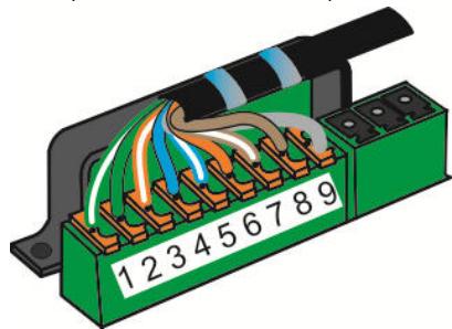
Figure 11: Anti-traction du cable CAT
For other products and distributors worldwide visit www.akg.com


ROHS OK
Technische Änderungen vorbehalten. Specifications subject to change without notice. Ces caractéristiques sont susceptibles de modifications. Ci riserviamo il diritto di effettuare modifiche tecniche. Nos reservamos el correcho de introducir modificaciones sociales. Especificações sujeitas a mudanças sem avis的前提。
10/10/9100 U 13390
- Safety and Environment
- Safety
- Risk of hearing loss!
- Environment
- Description
- Introduction
- Items supplied with starter kit
- Optional Accessories
- Summary
- Modules
- MASTER CONTROL
- D-MIC IN
- C-MIC IN
- CD/PCIN
- MP3/PC IN
- XLR OUT ACT.
- CONTROL
- REC OUT
- XLR OUT PAS.
- TRAFO IN
- TRAFO OUT
- PSU 10
- Installation and Connection
- RISK OF INJURY!
- Assembly sequence
- RISK OF DAMAGE!
- Connecting the modules
- Preparing the cabling
- CABLE LENGTH
- Installing in cable ducts:
- Flush mounting:
- Stripping the CAT cable
- REMOVING THE SHIELDING
- EARTH POTENTIAL
- Wiring the modules
- DETACHING INDIVIDUAL WIRES
- Connecting TRAFO IN
- You will need:
- Jumpers
- Module wiring diagram
- AMM 10 wiring diagram
- WIRING DIAGRAMS
- Operation
- Maximum number within the AMM 10 system:
- EARTH LOOP
- USB SOCKET
- POWER SUPPLY
- Cleaning
- Specifications
- Input:
- System output:
- Power supply:
- System cable connections:
- Expansion connectors:
- General:
- Charging socket:
- Output:
- Terminals:
- Troubleshooting
- Copyright
- Sommaire
Brand : AKG
Model : AMM 10
Category : Wireless Microphone System