
GS-105A - Network switch ZYXEL - Free user manual and instructions
Find the device manual for free GS-105A ZYXEL in PDF.
| Product type | Unmanaged network switch |
| Model | GS-105A |
| Brand | ZYXEL |
| Number of ports | 5 RJ-45 Ethernet ports |
| Port speed | 10/100/1000 Mbps (auto-negotiation) |
| Supported cable type | UTP/STP Category 3, 4, 5 or higher |
| Maximum cable length | 100 meters (328 feet) |
| Network features | Auto-MDI/MDIX, full-duplex/half-duplex, store-and-forward |
| Power supply | External power adapter (included) |
| Power consumption | Approximately 5 W (estimated) |
| Dimensions (W x D x H) | Approximately 14.5 x 9.0 x 3.0 cm |
| Weight | Approximately 0.3 kg |
| LED indicators | PWR (green), 100/1000 (green/orange), LNK/ACT (green), FDX/COL (orange) |
| Operating temperature | 0 °C to 40 °C (estimated) |
| Operating humidity | 10% to 90% non-condensing (estimated) |
| Certifications | FCC Class A, CE, BSMI |
| Warranty | 2 years (according to ZyXEL conditions) |
| Installation | On a desk, flat and stable surface |
| Maintenance and cleaning | Disconnect before cleaning; use a dry, soft cloth |
| Safety | Do not obstruct ventilation openings; avoid liquids |
| Spare parts and repairability | Not user-repairable; contact ZyXEL support |
Frequently Asked Questions - GS-105A ZYXEL
User questions about GS-105A ZYXEL
0 question about this device. Answer the ones you know or ask your own.
Ask a new question about this device
Download the instructions for your Network switch in PDF format for free! Find your manual GS-105A - ZYXEL and take your electronic device back in hand. On this page are published all the documents necessary for the use of your device. GS-105A by ZYXEL.
USER MANUAL GS-105A ZYXEL
Interference Statements and Warnings
FCC Interference Statement
This device complies with Part 15 of the FCC rules. Operation is subject to the following two conditions:
(1) This device may not cause harmful interference.
(2) This device must accept any interference received, including interference that may cause undesired operations.
FCC Warning
This equipment has been tested and found to comply with the limits for a Class A digital device, pursuant to Part 15 of the FCC Rules. These limits are designed to provide reasonable protection against harmful interference in a commercial environment. This equipment generates, uses, and can radiate radio frequency energy and, if not installed and used in accordance with the instruction manual, may cause harmful interference to radio communications. Operation of this equipment in a residential area is likely to cause harmful interference in which case the user will be required to correct the interference at his own expense.
CE Mark Warning
This is a class A product. In a domestic environment this product may cause radio interference in which case the user may be required to take adequate measures.
Taiwanese BSMI (Bureau of Standards, Metrology and Inspection) A Warning
警告使用者
Refer to the product page at
www.zyxel.com.
ZyXEL Limited Warranty
ZyXEL warrants to the original end user (purchaser) that this product is free from any defects in materials or workmanship for a period of up to two (2) years from the date of purchase. During the warranty period and upon proof of purchase, should the product have indications of failure due to faulty workmanship and/or materials, ZyXEL will, at its discretion, repair or replace the defective products or components without charge for either parts or labor and to whatever extent it shall deem necessary to restore the product or components to proper operating condition. Any replacement will consist of a new or re-manufactured functionally equivalent product of equal value, and will be solely at the discretion of ZyXEL. This warranty shall not apply if the product is modified, misused, tampered with, damaged by an act of God, or subjected to abnormal working conditions.
Note
Repair or replacement, as provided under this warranty, is the exclusive remedy of the purchaser. This warranty is in lieu of all other warranties, express or implied, including any implied warranty of merchantability or fitness for a particular use or purpose. ZyXEL shall in no event be held liable for indirect or consequential damages of any kind of character to the purchaser.
To obtain the services of this warranty, contact ZyXEL's Service Center for your Return Material Authorization number (RMA). Products must be returned Postage Prepaid. It is recommended that the unit be insured when shipped. Any returned products without proof of purchase or those with an out-dated warranty will be repaired or replaced (at the discretion of ZyXEL) and the customer will be billed for parts and labor. All repaired or replaced products will be shipped by ZyXEL to the corresponding return address, Postage Paid. This warranty gives you specific legal rights, and you may also have other rights that vary from country to country.
Getting to Know Your Switch
Introduction
The switch is a multi-port switch that can be used to build high-performance switched networks. The switch is a store-and-forward device that offers low latency for high-speed networking. The switch is designed for SOHO (Small Office Home Office) businesses.
Standalone Workgroup Application
The switch can be used as a standalone switch to which computers, servers and print server are directly connected to form a small workgroup.
Standalone Workgroup Example
Hardware Installation and Connection
The switch is suitable for an office environment where it can be placed on a desktop.
Desktop Installation
Step 1. Make sure the switch is clean and dry.
Step 2. Set the switch on a smooth, level flat space strong enough to support the weight of the switch and the connected cables. Make sure there is a power outlet nearby.
Step 3. Use the supplied power adapter to connect your switch to a power source. Refer to the label on the power adapter for more information.
Do not block the ventilation holes.
Rear Panel Power Connection
Connect one end of the supplied power adaptor to the power port on the rear panel of the switch and the other end to the appropriate power source. The PWR LED turns on.
Port Connection
For GS-105, the Ethernet ports are located on the rear panel. For GS-108, the Ethernet ports are located on the front panel.

natural_image
Dark blue background with a small black square labeled 'POWER' in the top right corner (no other text or symbols)Figure 1 Rear Panel: GS-108

natural_image
Front view of a network switch port with five ports and a power button (no text or symbols on the switches)Figure 2 Rear Panel: GS-105
RJ-45 Auto-negotiating Ports
Your switch comes with 5 or 8 10/100/1000M RJ-45 ports depending on the model of your switch. The auto-negotiation feature allows the switch to detect the speed of incoming transmission and adjust appropriately without manual intervention. It allows data transfers of 10 Mbps, 100 Mbps or 1000 Mbps in either half-duplex or full-duplex mode depending on your Ethernet network.
Auto-sensing (MDI/MDIX) Ethernet Ports
Each Ethernet port allows you to connect to a computer or to a hub using either a straight-through or a crossover Ethernet cable.
The following table describes the types of network cable used for the different connection speeds.
Table 1 Ethernet Cable Type
| SPEED | NETWORK CABLE TYPE |
| 10 Base-T | 100 2-pair UTP/STP Category 3, 4 or 5 |
| 100 Base-TX | 100 2-pair UTP/STP Category 5 |
| 1000 Base-T | 100 4-pair UTP/STP Category 5 |
Cable length between connections must not exceed 100 meters (328 feet).
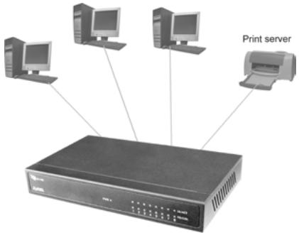
Front Panel LEDs
The LEDs on the front panel indicate the real-time status of the switch.
Figure 3 Front Panel LED: GS-108
The following table gives descriptions of the LEDs.
Table 2 Front Panel LED Descriptions
| LED | COLOR | STATUS | DESCRIPTION |
| PWR | Green | On | The switch is on and receiving power. |
| Off | The switch is not receiving power. | ||
| 100/1000 | Green | On | The port is operating at 1000Mbps. |
| Off | The port is operating at 10Mbps or no device is attached. | ||
| Orange | On | The port is operating at 100Mbps. | |
| Off | The port is operating at 10Mbps or no device is attached. | ||
| LNK/ACT | Green | On | The port is connected to an Ethernet network. |
| Off | The port is not connected to an Ethernet network. | ||
| Blinking | The port is receiving or transmitting data. | ||
| FDX/COL | Orange | On | The port is operating in full-duplex mode. |
| Blinking | Packet collision occurred on this port. | ||
| Off | The port is operating in half-duplex mode or no Ethernet device is connected to this port. |
- Interference Statements and Warnings
- FCC Interference Statement
- FCC Warning
- CE Mark Warning
- Taiwanese BSMI (Bureau of Standards, Metrology and Inspection) A Warning
- ZyXEL Limited Warranty
- Note
- Getting to Know Your Switch
- Introduction
- Standalone Workgroup Application
- Hardware Installation and Connection
- Desktop Installation
- Rear Panel Power Connection
- Port Connection
- RJ-45 Auto-negotiating Ports
- Auto-sensing (MDI/MDIX) Ethernet Ports
- Front Panel LEDs
Brand : ZYXEL
Model : GS-105A
Category : Network switch