
MECABLITZ 58 AF-1 P DIGITAL - External Flash METZ - Free user manual and instructions
Find the device manual for free MECABLITZ 58 AF-1 P DIGITAL METZ in PDF.

| Brand | Metz |
| Model | Mecablitz 58 AF-1 P Digital |
| Product Type | External flash for compatible Pentax and Samsung cameras |
| Max guide number (ISO 100/21°, zoom 105 mm) | 58 (meters) / 192 (feet) |
| Color temperature | Approximately 5600 K |
| ISO sensitivity range | ISO 6 to 6400 |
| Operating modes | TTL, P-TTL, Automatic A, Manual M, Stroboscope, Spot Beam |
| Special functions | HSS, 1st/2nd curtain sync, red-eye reduction, AF illuminator, pilot light, secondary reflector, wireless P-TTL remote, exposure compensation ±3 EV |
| Motorized zoom of main reflector | Automatic or manual, from 24 mm to 105 mm (18 mm with wide-angle diffuser) |
| Head orientation | Vertical: -7° to 90°; Horizontal: 0° to 180° (left/right) |
| Power supply | 4 AA batteries (NiCd, NiMH, alkaline, lithium) or Power Pack P76 (optional) |
| Battery life (full power) | Approximately 180 flashes with NiMH 1600 mAh batteries; approximately 430 with Power Pack P76 |
| Recycling time (full power) | Approximately 5 s with NiMH batteries; approximately 2.5 s with Power Pack P76 |
| Dimensions (H × W × D) | 71 × 148 × 99 mm |
| Weight (with batteries) | Approximately 355 grams |
| Maintenance and cleaning | Use a soft, dry or silicone cloth; do not use detergent. Form the capacitor every 3 months if not in use. |
| Safety | Do not fire near flammable gas, eyes; do not expose to heat; do not disassemble (high voltage); stop after 15 flashes at full power to avoid overheating. |
| Spare parts and repairability | Firmware update via USB; factory reset. Optional accessories: Mecabounce 58-90, reflector screen 58-23, Power Pack P76, cable V58-50. |
| General information | Dedicated flash for Pentax and Samsung SLR cameras with TTL/P-TTL control. Compatible with wireless P-TTL Remote system. Warranty: refer to manufacturer's conditions. |
Frequently Asked Questions - MECABLITZ 58 AF-1 P DIGITAL METZ
User questions about MECABLITZ 58 AF-1 P DIGITAL METZ
0 question about this device. Answer the ones you know or ask your own.
Ask a new question about this device
Download the instructions for your External Flash in PDF format for free! Find your manual MECABLITZ 58 AF-1 P DIGITAL - METZ and take your electronic device back in hand. On this page are published all the documents necessary for the use of your device. MECABLITZ 58 AF-1 P DIGITAL by METZ.
USER MANUAL MECABLITZ 58 AF-1 P DIGITAL METZ
MECABLITZ 58 AF-1 P digital
P T L Mode flash P-TTL
PHTHSS Mode flash TTL haute vitesse rapide P-TTL-HSS
5.4 Dosage flash/ambiance /P
5.9 Mode spot beam "SB"
7.7 Commutation metres - pieds (m / ft)
PTLHSS High-Speed-flitsfunctionie P-TTL-HSS
7.2 Beep-function (Beep)
[3] Knippert langzaam
8.2 Exposure control indicator in TTL flash mode 107
8.3 Warning indicator 107
9.Motor Zoom Reflector 107
10. Wide-angle diffuser 108
11. Flash techniques 108
11.1 Bounce flash 108
11.2 Bounce flash with a reflector card 108
11.3 Bounce flash with secondary reflector 108
11.4 Close-ups / macro shots 109
11.5 Manual flash exposure corrections 109
12. Flash readiness indication 109
13. Automatic flash sync speed control 110
14. Correct exposure indication 110
15. Flash range indication 110
16. Flash synchronisation 111
16.1 Normal synchronisation 111
16.2 Second curtain synchronisation (REAR, 2nd curtain, SLOW2) 111
16.3 Slow synchronisation / SLOW 111
16.4 High-speed flash mode P-TTL-HSS 111
16.5 Triggering control 112
17. Preflash function for red-eye reduction 112
18. Multi-zone AF measuring beam 112
19. Wireless P-TTL - remote system 113
19.1 Activating the remote flash mode as master 113
19.2 Activating the remote flash mode as Controller 114
19.3 Activating the remote flash mode as Slave 114
19.4 Deactivating the remote mode 115
20. Care and maintenance. 115
20.1 Firmware updates. 115
20.2 Reset 115
20.3 Flash capacitor forming 115
21. Troubleshooting 115
22. Technical data 118
23. Optional accessories 119
Table 3: Guide numbers at maximum light output (P 1) 179
Table 4: Flash durations at the individual partial light output levels. 180
Table 5: Camera shutter speeds in stroboscopic mode 181
Table 6: Recycling times and number of flashes with different battery types. 182
Table 7: Maximum guide numbers at HSS-Mode. 182
Introduction
Thank you for purchasing a Metz product. We are happy to welcome you as a customer.
Of course, you are excited to start using the flash unit right away. However, it is worthwhile reading the operating instructions first to learn how to use the flash correctly.
This flash unit is suited for:
- Analogue and digital Pentax cameras with TTL or P-TTL flash control and flash socket system, as well as compatible digital cameras from Samsung
This flash unit is not suited for other brands of cameras. Also take a look at the image page at the end of the manual.
1. Safety instructions
- The flash unit is intended and approved exclusively for photographic use!
- Never fire a flash in the vicinity of flammable gases or liquids (petrol, solvents, etc.)! DANGER OF EXPLOSION!
- Never take flash shots of car, bus or train drivers, or of motorcycle and bicycle riders while they are in motion. They could be blinded by the flash and cause an accident!
- Never fire a flash in the immediate vicinity of the eyes! A flash fired into the eyes of a person or animal at close range may damage the retina and lead to severe visual disorders, including blindness!
- Only use the approved power sources listed in the Operating Instructions!
- Do not expose batteries to excessive heat sources such as sunshine or fire!
- Never throw flat/dead batteries onto a fire!
- Dead batteries should be removed from the flash unit immediately, as lye leaking from dead batteries can damage the flash unit.
-
Never recharge dry cell batteries!
-
Do not expose the flash unit or battery charger to dripping or splashing water such as rain!
- Protect the flash unit from excessive heat and humidity! Do not store the flash unit in the glove compartment of a car.
- When a flash is fired, no opaque material may be in front of or directly on the reflector screen of the flash unit, nor may there be dirt on the reflector screen. The high heat generated by the flash can cause such material to burn or cause damage to the reflector screen.
- Do not touch the reflector screen after a series of flash shots, as you may burn yourself.
- Never disassemble the flash unit! DANGER: HIGH VOLTAGE! There are no components inside the flashgun that can be repaired by a layman.
- When taking a series of flash shots at full light output and with the rapid recycling times possible with NiCad/NiMH battery operation, make sure to wait for at least 10 minutes after 15 flashes. Otherwise, the flash unit will be overloaded.
- When taking a series of flash shots at full light output and with rapid recycling times, and with zoom positions of 35mm and less, the diffuser heats up, due to the high level of thermal energy. To protect itself from overheating, the flash unit will automatically increase the recycling time.
- This flash unit may be used in combination with a camera-integrated flash only if the flash can be folded out completely.
- Rapid changes in temperature may lead to condensation. If this occurs, allow time for the unit to become acclimatized.
- Never use defective batteries of any type with this flash unit.
2. Dedicated flash functions
Dedicated flash functions are flash functions that have been specially adapted to a given camera system. Depending on the type of camera, different flash functions are supported.
- Flash-ready indication in camera viewfinder/camera display
- Exposure control indication in camera viewfinder with TTL
Automatic flash sync speed control - Flash bracketing „FB“
Automatic flash / triggering control - Contrast control
- Spot beam mode „SB"
- TTL flash mode
- P-TTL flash mode
Automatic TTL-/P-TTL-fill-in flash control - Manual flash exposure correction
- 1st or 2nd curtain-synchronisation (REAR, 2nd curtain, SLOW2)
High-speed flash mode P-TTL-HSS
Automatic motor zoom control
Automatic AF measuring beam control (multi-zone AF measuring beam)
Automatic flash range indication - Programmed flash mode
- Preflash function for reducing the red-eye effect
- Wireless P-TTL remote flash mode
- Wake-up function for the flash unit
- Firmware update via USB connector
It is impossible to describe all camera types and their individual dedicated flash functions within the scope of these instructions. Therefore, please refer to the flash mode description in your camera's operating instructions to find out which functions are supported and which ones have to be set manually on the camera.
3. Preparing the flash unit for use
3.1 Mounting the flash unit
Mounting the flash unit on the camera
Turn off the camera and flash before mounting or removing.
- Turn the knurled nut ⑥ towards the flash unit housing as far as it will go. The locking pin in the adapter shoe is now fully retracted into the case.
- Slide the flash unit foot completely into the camera accessory shoe.
- Turn the knurled nut ⑥ towards the camera housing as far as it will go, clamping the flash unit in place. If the camera does not have a locking hole, the spring-loaded locking pin retracts into the adapter case so as not to damage the surface.
Removing the flash unit from the camera
Turn off the camera and flash before mounting or dismounting.
- Turn the knurled nut ⑥ towards the flash unit housing as far as it will go.
- Remove the flash unit from the camera's accessory shoe.
3.2 Power supply
Suitable batteries/rechargeable batteries
The flash unit can be operated with any of the following batteries:
- 4 NiCad batteries 1.2V, type IEC KR (size AA). They permit very fast recycling times and are economical in use because they are rechargeable.
- 4 nickel-metal-hydride batteries 1.2V, type IEC HR6 (size AA). They have a significantly higher capacity than NiCad batteries and are less harmful to the
environment, since they have no cadmium.
- 4 alkaline-manganese dry cell batteries 1.5V, type IEC LR6 (size AA). Maintenance-free power source for moderate power requirements.
- 4 lithium batteries 1.5V , type IEC FR6 (size AA). Maintenance-free high-capacity power source with a low self-discharge rate.
- Power Pack P76 with connecting cable V58-50 (optional accessory)
If your flash unit is not going to be used for an extended period of time, remove the batteries.
Replacing batteries
The batteries are flat or dead if the recycling time (elapsing from the triggering of a full-power flash, e.g. in the M mode, to the moment the flash ready indicator lights up again) exceeds 60 seconds.
- Turn off the flash unit at the main switch (15).
- Slide the battery compartment cover ⑧ downwards and fold open.
- Insert the batteries lengthwise as indicated by the battery symbols on the flash unit, and close the battery compartment cover ⑧ .
When inserting batteries, ensure that the polarity is correct and matches the symbols in the battery compartment. Inserting the batteries in the wrong direction can destroy the flash unit! Always replace all batteries simultaneously, and make sure that batteries are the same brand and have the same capacity. Flat or dead batteries should not be disposed of with ordinary household waste. Help protect the environment, and dispose of flat/dead batteries at the appropriate collection points.
3.3 Switching the flash unit on and off
The flash unit can be turned on by flipping the main switch ⑤ to the "ON" position. To turn off the flash unit, flip the main switch ⑤ to the left position.
If your flash unit is not going to be used for an extended period of time, we recommend turning it off with the main switch and removing the power source (i.e., batteries).
3.4 Power Pack P76 (optional accessory)
If a battery-operated flash does not meet your needs in terms of number of flashes and recycling times, a Power Pack P76 (optional) can be connected to the flash unit to provide extra power. A V58-50 connecting cable (optional) is necessary for connecting the Power Pack P76 to the flash unit.
In this case, no batteries have to be inserted into the flash unit.
When attaching the Power Pack P76 or the V58-50 connecting cable (accessory) to the flash unit, the main switch of the flash must be in the left "OFF" position. The flash unit is then turned on or off using the switch on the Power Pack P76 (see Operating Instructions for the Power Pack).
To protect the flash unit from thermal overload when connected to the Power Pack, a monitoring control increases the recycling times during heavy usage. Both flash unit and Power Pack should be switched off before the connecting cable is attached or removed from either unit.
3.5 Auto OFF for the flash unit
To save battery power and prevent inadvertent battery drain, the flash unit is factory-set to automatically switch to standby mode (Auto OFF) 10 minutes after
- being switched on,
- a flash is fired
the shutter release is actuated - the camera's exposure metering system is switched off. ...The flash readiness indicator and the LC display are also switched off.
If the flash is manually switched on again, the last settings prior to the automatic switch off are retained and immediately available. The flash unit can be reactivated by pressing any button or by lightly depressing the shutter release (wake up function). The flash unit should always be turned off using the main switch if it is not going to be used for an extended period.
If necessary, the Auto OFF function can be set to occur after 1 minute of inactivity, or can be deactivated (see 7.10).
4. Display illumination
Every time a button on the flash unit is pressed, the flash display illumination is activated for 10 seconds. When a flash is fired via the camera or a hand release, the display lightning 416 on the flash unit is switched off.
5. Operating modes (mode menu)
The flash unit supports TL, PTL, automatic A, manual M, SB and stro-boscope modes
Depending on the type of camera, other flash modes may be supported. These flash operating modes can be selected and activated in the mode menu following a data transfer with the camera. Depending on the system, some camera models (depending on the camera's operating mode) only support the TTL-/P-TTL flash mode. Other flash modes (automatic A, manual M etc.) cannot be selected or activated!
5.1 Adjusting procedure for flash operating modes
- Press the "Mode" button until the word "Mode" appears on the display. You can choose from the following operating modes:
TTL flash mode
P-TTL flash mode
P HSS High speed flash mode P-TTL-HSS
A Automatic flash mode
M Manual flash mode
Stroboscope flash mode
SB Spot beam mode "SB"
- Set the flash mode of your choice (TTL, automatic A, manual M, etc.) using the UP ▲ and DOWN▼ keys. The flash mode you choose is then highlighted. The settings take effect immediately.
- Press the "Return" button → , and the display changes back to the normal view. If the "Return" button → is not pressed, the display will change back to the normal view after about 5 seconds.
The flash parameters for ISO, aperture and lens focal length or mirror position are set automatically, if the camera transfers the necessary data to the flash unit. The range indicator on the display of the control unit matches the flash parameters transferred from the camera.
If the camera does not transfer one or more flash parameters to the flash unit, you will have to adjust these settings by hand (see 6).
5.2 TTL- flash mode
The TTL flash mode offers a very simple method of achieving excellent flash shots. In this mode, exposure readings are taken by a sensor built into the camera which measures the amount of light through the camera lens (TTL). The electronic control circuit within the camera transmits a stop signal to the flash unit after sufficient light has been emitted, instantly interrupting the flash. The advantage of this flash mode is that all factors influencing correct exposure (filters, change of aperture and focal length with zoom lenses, extensions for close-ups, etc.) are automatically taken into account.
TTL flash mode is supported by all modes of camera operation.
Different types of digital cameras only support the P-TTL flash mode (see 5.3)!
Setting procedure:
- Press the "Mode" button until "Mode" flashes on the LC display.
- Set the HL flash mode using the UP and DOWN keys. The flash mode you choose is then highlighted. The setting takes effect immediately.
- Press the "Return" button → to change the display back to the normal view. If the "Return" button → is not pressed, the display will change back to the normal view after about 5 seconds.
If the shot was properly lit, the correct exposure indication ⑭ will flash "OK" for about 3 seconds (see 14).
5.3 P-TTL flash mode
The P-TTL flash mode with measuring preflash is a further development of the standard TTL flash mode of analogue cameras. During the shot and before the actual exposure, one or more almost indiscernible preflashes are executed by the flash unit. The light reflected by the preflash is evaluated by the camera. According to the evaluation, the subsequent flash exposure will be adjusted by the camera to suit the situation (see the camera's operating instructions).
Depending on the camera model, the preflashes precede the main flash by such a short interval that they practically cannot be distinguished from the main flash! The preflashes do not contribute to the lighting of the shot.
Setting procedure:
- Press the "Mode" button until "Mode" flashes on the LC display.
- Set the PTL flash mode using the UP and DOWN keys. The flash mode you choose is then highlighted. The setting takes effect immediately.
- Press the "Return" button → to change the display back to the normal view. If the "Return" button → is not pressed, the display will change back to the normal view after about 5 seconds.
If the shot was properly lit, the correct exposure indication ④ will flash "OK" for about 3 seconds (see 14).
In order to be able to work with slower shutter speeds than the flash sync speed it is possible to activate the P-TTL-HSS high-speed flash mode in the P-TTL flash mode depending on the type of camera (see 16.4).
5.4 ML / PMLfill-in flash mode
With most camera models, the auto programme mode P and subject programmes activate the automatic fill-in flash mode in daylight (see the camera's operating instructions) when in TTL- or P-TTL mode.
With the fill-in flash you can remove annoying shadows and achieve a balanced exposure between motive and background in shots with backlight. A computer-controlled metering system takes care of the appropriate combination of shutter speed, working aperture and flash output.
Ensure that the frontlighting source does not shine directly into the lens, as this will interfere with the camera's TTL metering system.
Ensure that the centre-jour light source does not shine directly into the lens, as this will interfere with the camera's TTL metering system.
An adjustment or display for the automatic TTL fill-in flash mode on the flash unit doesn't occur in this case.
5.5 Automatic flash mode
In the automatic flash mode A, the flash unit sensor ⑩ measures the light that reflects back from the subject. The sensor ⑩ has a coverage of about 25irc , and only measures the light for the time a flash is fired by the mecablitz. The flash is cut off as soon as sufficient light has been emitted for correct exposure. The sensor ⑩ of the mecablitz has to be directed at the subject.
The maximum range is shown on the LC display. The shortest shot distance is approximately 10% of the maximum distance range. The subject should be located within the middle third of the distance range shown on the LC display to allow the electronic system sufficient leeway for compensation.
Setting procedure:
-
Press the „Mode" button until „Mode" flashes on the LC display.
-
Set the flash mode A using the UP and DOWN keys. The flash mode selected is then highlighted. The setting takes effect immediately.
- Press the "Return" button → to change the LC display back to the normal view. If the "Return" button → is not pressed, the display will change back to the normal view after about 5 seconds.
If the shot was properly lit, the correct exposure indication ⑭ will flash "OK" for about 3 seconds (see 14).
5.6 Automatic flash mode
When shooting in automatic fill-in flash mode in daylight, the automatic flash mode A will automatically set a correction of between -1 and -2 f-stops to compensate for flash exposures (see 6.3 and 11.5).
This has a graduated lightening effect on shadowy areas, which has a natural appearance on the photograph.
5.7 Manual flash mode
In the manual flash mode M, the flash unit emits the full uncontrolled amount of light if no partial light output has been selected. The specific photographic situation can be taken into account by making adjustments to the aperture setting or by selecting a suitable partial light setting.
Setting procedure:
- Press the "Mode" button until "Mode" flashes on the LC display.
- Choose the flash mode M using the UP ▲ and DOWN▼ arrows. The flash mode M is then highlighted. The setting takes effect immediately.
- Press the "Return" button to change the LC display back to the normal view. If the "Return" button is not pressed, the display will change back to the normal view after about 5 seconds.
Set partial light output:
-
Press the "Para" button (Parameters) until "P" flashes on the LC display for partial light output.
-
Set the desired light output (1/1-1/256) with the + / - buttons. The setting takes effect immediately.
- Press the "Return" button to change the LC display back to the normal view. If the "Return" button is not pressed, the display will change back to the normal view after about 5 seconds.
The mecablitz LC display will indicate the flash-to-subject distance required for a correct flash exposure.
Some cameras only support the M manual flash mode when the camera is set to the manual operating mode M.
5.8 Strobe flash mode
The strobe flash mode is a manual flash mode. It allows several flash exposures to be made on a single photo, which can be especially interesting for movement studies or special effect images. In strobe flash mode, several flashes at a certain flash frequency are emitted. For this reason, this function is only possible with a partial light output of 1/4 or less.
The flash frequency (flashes per second) for a stroboscope image can be set between 1 ... 50 Hz in 1 Hz intervals, and the number of flashes can be set between 2 ... 50 in intervals of one.
Setting procedure:
- Press the "Mode" button until "Mode" flashes on the LC display.
- Choose the flash mode using the UP and DOWN arrows. The flash mode is then highlighted. The setting takes effect immediately.
- Press the "Return" button → to change the LC display back to the normal view. If the "Return" button → is not pressed, the display will change back to the normal view after about 5 seconds.
Strobe number of flashes (N)
In strobe mode, the number of flashes per shot (N) can be selected.
The number of flashes can be set from 2 to 50 in intervals of one. The maximum manual partial light output is automatically adjusted to this number.
Strobe flash frequency (f)
Strobe mode allows you to select the flash frequency (f), which indicates the number of flashes per second. The number of flashes can be set from 1 to 50 in intervals of one. The maximum manual partial light output is automatically adjusted to this number.
Setting procedure:
- Press the "Para" button (Parameters) until the desired flash parameter (N or f) flashes on the LC display.
- Set the desired value using the + / - buttons. The setting takes effect immediately.
- Press the "Return" button → to change the LC display back to the normal view. If the "Return" button → is not pressed, the display will change back to the normal view after about 5 seconds.
The maximum possible partial light output depends on the ISO and aperture settings, and is automatically set in strobe mode. If you desire short flashes, you can manually reduce the partial light output to the lowest value of 1/256.
The mecablitz LC display will indicate the flash-to-subject distance required for a correct flash exposure, given the parameters selected. By changing the aperture setting or the partial light output, this value can be adjusted to fit the actual distance to the subject.
Setting procedure:
- Press the "Para" button (Parameters) until the desired flash parameter (P=partial light output) appears on the LC display.
- Set the desired value using the + / - buttons. The setting takes effect immediately.
- Press the "Return" button → to change the LC display back to the normal view. If the "Return" button → is not pressed, the display will change back to the normal view after about 5 seconds.
The secondary reflector is not supported in the Stroboscopic flash mode. If
the secondary reflector was activated in the select menu, it will not also flash in the Stroboscopic flash mode! In the display, the symbol for the secondary reflector will not be shown!
5.9 Spot-beam mode
In the spot beam mode, the AF measuring beam can be used to focus on a subject at low ambient light level without firing a flash when the shot is taken.
There is no flash-ready indicator in spot beam mode and no exposure control indicator in the camera viewfinder. The camera is not set to its sync speed and behaves as though there were no flash unit connected.
U Spot beam mode is only activated when the flash unit is switched on and is flash-ready (check the flash-ready indicator on the flash unit!).
When the camera shutter is released, no flash is fired. Please read the notes on the AF measuring beam in chapter 18.
6. Flash parameters (Parameter menu)
For the flash unit to operate correctly, various flash parameters such as the zoom position of the main reflector, aperture, ISO light sensitivity, etc. have to be adjusted to match the camera.
For this automatic data transfer to occur, the flash unit has to be mounted on the camera, and both devices have to be switched on. In addition, a data exchange between the camera and flash unit has to be initiated, for which you simply briefly press the shutter release. The maximum range as per the current flash parameters is shown on the display.
6.1 Setting procedure for the flash parameters
When a button is pressed for the first time, the LC display is illuminated.
Depending on the flash mode set, various flash parameters are shown in the menu: For cameras with digital data transfer, the flash parameters for aperture (F), lens focal length (Zoom), and light sensitivity (ISO) are automatically set on the flash unit. The flash parameters for aperture (F) and light sensitivity (ISO)
cannot be changed.
- Press the "Para" button (Parameters) until the desired flash parameter (see below) appears on the LC display.
The following parameters are available:
| TTL/P-TTL/ P-TTL-HSS/A/SB | M/M HSS | ### | Table 1 |
| - | - | N | Number of strobe flashe |
| - | - | f | Strobe flash frequency |
| - | P | P | Manual partial light output |
| Zoom | Zoom | Zoom | Mainreflektor position |
| EV | - | - | Manual flash exposure correction |
- Set the desired value using the + / - buttons. The setting takes effect immediately.
- Press the "Return" button → to change the LC display back to the normal view. If the "Return" button → is not pressed, the display will change back to the normal view after about 5 seconds.
Depending on the system, the aperture setting will not be shown on the display of the flash!
6.2 Main reflector position (Zoom)
If there is no digital data transfer between the camera and flash unit, the reflector positions
24 mm - 28 mm - 35 mm - 50 mm - 70 mm - 85 mm - 105 mm (35mm format 24 x 36) can be set manually.
MZoom will then appear in the LC display.
Setting procedure:
- Press the "Para" button (Parameters) until "Zoom" appears on the LC display.
- Set the desired value using the + / - buttons. The setting takes effect immediately.
- Press the "Return" button → to change the LC display back to the normal view. If the "Return" button → is not pressed, the display will change back to the normal view after about 5 seconds.
During digital data transfer between the camera and flash unit, the main reflector positions are adjusted automatically.
AZoom will then appear in the LC display.
6.3 Flash exposure correction (EV)
Manual flash exposure correction (EV) can help offset extreme differences in contrast between the subject and background. Corrections from -3 f-stops (EV) to +3 f-stops (EV) can be made, in 1/3 increments (also see 11.5).
Flash exposure correction is only activated in the TTL and P-TTL flash modes if the camera supports this function (see the camera's operating instructions)! Flash exposure correction is activated in automatic flash mode A irrespective of the camera model!
Setting procedure:
- Press the "Para" button (Parameters) until "EV" flashes on the LC display.
- Set the desired EV value using the + / - buttons. The setting takes effect immediately.
- Press the "Return" button to change the LC display back to the normal view. If the "Return" button is not pressed, the display will change back to the normal view after about 5 seconds.
6.4 Manual partial light output (P)
In the manual mode M and the strobe mode , the light output can also be adjusted to fit the shooting situation with the manual partial light output parameter (P). Settings in manual flash mode M range from P 1/1 (full light output) to P 1/256, in intervals of 1/3.
Setting procedure:
- Press the "Para" button (Parameters) until "P" appears on the LC display.
- Set the desired light output (1/1-1/256) with the +/- buttons. The setting takes effect immediately.
- Press the "Return" button → to change the LC display back to the normal view. If the "Return" button → is not pressed, the display will change back to the normal view after about 5 seconds.
In strobe mode , the maximum partial light output is automatically adjusted to fit the flash parameters chosen.
In strobe mode , reduction of the manual partial light output is only possible in full intervals.
When the number of flashes (N) and the flash frequency (f) are reset, the partial light output is not reset.
7. Special functions (Select menu)
Special functions are selected using the „Sel" (Select) button. Depending on the camera model and flash mode set, various special functions are available. If certain special functions are not supported by your camera, these functions may not be displayed in the menu. Also see table 2 for more information.
7.1 Setting procedure for the special functions
- Press the "Sel" key repeatedly until "Select" appears on the display.
- Use the UP and DOWN arrows to select the item of your choice or special function from the menu. The selected menu item will be highlighted against a dark background.
The following special functions are available, depending on the mode and camera model:
Table 2
| TTL/P-TTL | A | M/M HSS | |
| - | |||
| REAR | REAR | REAR | - |
| Contrast | - | - | - |
| Beep | Beep | Beep | Beep |
| Remote | Remote | Remote | Remote |
| FB | FB | - | - |
| Standby | Standby | Standby | Standby |
| ML | ML | ML | ML |
| KEYLOCK | KEYLOCK | KEYLOCK | KEYLOCK |
| ZoomExt | ZoomExt | ZoomExt | ZoomExt |
| ZoomSize | ZoomSize | ZoomSize | ZoomSize |
| m / ft | m / ft | m / ft | m / ft |

- Press the "Set" key to confirm the special function selection.
- Choose the setting desired using the UP and DOWN arrows. The setting takes effect immediately.
- Press "Return" → repeatedly to return the display to its normal reading. If the "Return" button → is not pressed, the display will change back to the normal view after about 5 seconds.
7.2 Beep function (Beep)
The beep function allows the user to receive an acoustic signal for certain functions of the flash unit. This allows the photographer to concentrate fully on the subject and taking the picture, and not have to worry about any optical status indicators.
The beep function signals when the flash is ready, when the correct flash exposure has been reached, or when an error occurs.
Acoustic signals after the flash unit has been turned on:
- A short (about two seconds) uninterrupted beep signal after turning the flash on indicates that the flash unit is ready.
Beep signals after taking a photograph:
- A short (about two seconds) uninterrupted beep signal directly after a picture is taken indicates that the shot was exposed correctly and the flash is ready again. If no beep signal sounds, then the shot was underexposed.
- A broken (- - - ) beep signal directly after a shot indicates that the shot was correctly exposed. The flash is only ready however after a second (about two seconds) continuous beep.
Beep signals when adjusting automatic mode settings:
- A short beep signal as an alarm in automatic mode indicates that the aperture and ISO settings exceed the permissible light control range. The auto aperture of the mecablitz is then automatically adjusted to the next permissible value.
When the beep function is turned on, the symbol is also displayed on the LC display.
Setting procedure:
- Press the "Sel" button repeatedly until "Select" appears on the display.
- Use the UP ▲ and DOWN▼ buttons to select „BEEP" from the menu. The selected menu item will be highlighted against a dark background.
- Press the "Set" key to confirm the special function selection.
- Choose the setting desired using the UP and DOWN arrows. The setting takes effect immediately.
- Press "Return" → repeatedly to return the display to its normal reading. If the "Return" key → not pressed, the display will switch back to normal automatically after approximately 5 seconds.
7.3 Flash Bracketing Series (FB)
A series of flash exposures (flash-bracketing FB) can be carried out in the and automatic A flash modes. A flash bracketing series consists of three successive flash shots with different flash exposure correction values.
T
When a flash bracketing series is set, FB and the correction value appear on the display. The possible correction values range from 1/3 to 3 apertures in one-third aperture increments.
Setting procedure:
- Press the "SEL" button repeatedly until "Select" appears on the display.
- Select the menu option "FB" by pressing the UP and DOWN buttons. The selected menu option will be highlighted.
- Confirm the selection of the special function by pressing the "Set" button.
- Select the desired setting with the UP and DOWN buttons. The setting takes effect immediately.
- Press the "Return" button → repeatedly until the screen is reset to its normal view. If the "Return" button → is not pressed, the display is automatically reset to its normal view after about 5 seconds.
When nFB0 is displayed, the flash bracketing series is deactivated.
- The first shot is taken without a correction value. "FB 1" will also appear on the display.
- The second shot is taken with minus correction. "FB 2" and the minus correction value (EV) will also appear on the display.
- The third shot is taken with plus correction. "FB 3" and the plus correction value (EV) will also appear on the display.
- After the third shot, the flash bracketing series is automatically deleted. "FB" will disappear from the display.
When the flash bracketing series is set, the correction value is always shown as a positive value!
Flash bracketing series in the TTL/P-TTL flash mode
A flash bracketing series in the TTL flash mode is only possible if the camera supports the setting of a manual flash exposure correction on the flash unit (see camera instruction manual)! Otherwise, the shots are taken without a correction value!
Flash bracketing in automatic flash mode A
The type of camera is not important for a flash bracketing series in automatic flash mode A.
7.4 Extended Zoom Mode (Zoom Ext)
In the extended zoom mode, the focal length of the main reflector is reduced to one level below the focal length of the camera lens. The resulting broader light coverage provides additional dispersed light (reflections) inside rooms so that a softer flash illumination is possible.
Example:
The focal length of the camera lens is 50 mm . The extended zoom mode sets a 35 mm reflector position on the flash unit. However, 50 mm continues to be shown on the display.
- When „Ext ON" is displayed, the extended zoom mode is activated.
- When „Ext OFF" is displayed, the extended zoom mode is deactivated.
Setting procedure:
- Press the "SEL" button repeatedly until "Select" appears on the display.
- Select the menu option „ZoomExt" by pressing the UP and DOWN keys. The selected menu option will be highlighted.
- Confirm the selection of the special function by pressing the "Set" button.
- Select the desired setting with the UP and DOWN keys. The setting takes effect immediately.
- Press the "Return" button → repeatedly until the screen is reset to its normal view. If the "Return" button → is not pressed, the display is automatically
reset to its normal view after about 5 seconds.
Once the extended zoom mode is activated, "EZoom" will appear on the display next to the focal length.
Depending on the system, the extended zoom mode is supported for lens focal lengths of 28 mm or more (35mm format).
7.5 Adjusting exposure format (Zoom Size)
With some digital cameras it is possible to adjust the light angle of the main reflector to suit the chip format (the dimensions of the image recording module).
- When „Size ON“ appears, Zoom Size is activated.
The reflector position display is adjusted to the image format of the digital cameras. - When „Size OFF“ appears, Zoom Size is deactivated.
The display of the reflector position is shown in small picture format (24 × 36) .
Setting procedure:
- Press the "SEL" button repeatedly until "Select" appears on the display.
- Select the menu option „ZoomSize" by pressing the UP and DOWN keys. The selected menu option will be highlighted.
- Confirm the selection of the special function by pressing the "Set" button.
- Select the desired setting with the UP and DOWN keys. The setting takes effect immediately.
- Press the "Return" button → repeatedly until the screen is reset to its normal view. If the "Return" button → is not pressed, the display is automatically reset to its normal view after about 5 seconds.
Once the Zoom Size mode is activated, "SZoom" will appear on the display next to the focal length.
Refer to your camera's instruction manual for further information.
7.6 Cordless remote mode (Remote)
- When „Remote OFF" appears, the cordless remote mode is deactivated.
- When "Remote Master" appears, the flash unit is operating as a guiding master flash unit on the camera.
- When „Remote Slave“ appears, the flash unit is operating completely as a slave flash unit. See also Section 19.
Setting procedure:
- Press the "SEL" button repeatedly until "Select" appears on the display.
- Select the "Remote" menu option by pressing the UP and DOWN keys. The selected menu option will be highlighted.
- Confirm the selection of the special function by pressing the "Set" button.
- Select the desired setting with the UP and DOWN keys. The setting takes effect immediately.
- Press the "Return" button → repeatedly until the screen is reset to its normal view. If the "Return" button → is not pressed, the display is automatically reset to its normal view after about 5 seconds.
7.7 Meter-Feet changeover (m/ft)
The maximum flash range indicated by the flash unit's display can either be shown in meters or feet. The setting can be adjusted under the menu option m/ft.
Setting procedure:
- Press the „SEL“ button repeatedly until „Select“ appears on the display.
- Select the "m/ft" menu option by pressing the UP and DOWN keys. The selected menu option will be highlighted.
- Confirm the selection of the special function by pressing the "Set" button.
-
Select the desired setting with the UP and DOWN keys. The setting takes effect immediately.
-
When m is displayed, distances will be shown in meters.
-
When ft'' is displayed, distances will be shown in feet.
-
Press the "Return" button → repeatedly until the display is reset to its normal state. If the "Return" button → is not pressed, the display is automatically reset to its normal view after about 5 seconds.
7.8 Secondary reflector
The secondary reflector i is used for frontal brightening in the case of indirect lighting when the main reflector is pivoted to the side or upwards (see 11.3). If the secondary reflector ⑨ produces too much light, it can be reduced to 1/2 or 1/4.
Off setting: Secondary reflector is turned off.
- P1 / 1'' setting: secondary reflector is operating at full light output.
- P1 / 2'' setting: secondary reflector is operating at 1/2 light output.
- P1 / 4'' setting: secondary reflector is operating at 1/4 light output.
When the secondary reflector is activated and the setting is saved, a symbol will appear in the display.
Depending on the camera model, the preflash function for reducing the red-eye effect is performed by the preflashes from the secondary reflector even if this isn't activated!
Setting procedure:
- Press the "SEL" button repeatedly until "Select" appears on the display.
- Select the menu option by pressing the UP and DOWN buttons. The selected menu option will be highlighted.
- Confirm the selection of the special function by pressing the "Set" button.
- Select the desired setting with the UP and DOWN buttons. The setting takes effect immediately.
- Press the "Return" button → repeatedly until the display is reset to its normal state. If the "Return" button → is not pressed, the display is automatically reset to its normal view after about 5 seconds.
Please also refer to the information in Section 11.3!
7.9 Modelling Light (ML)
The modelling light is a high-frequency stroboscopic flash. It creates the impression of a semi-permanent light for a duration of about 3 seconds. The modelling light enables the user to assess light distribution and the formation of shadows before taking pictures.
- The modelling light is activated when "ML ON" is displayed.
- The modelling light is deactivated when „ML OFF“ is displayed.
Setting procedure:
- Press the "SEL" button repeatedly until "Select" appears on the display.
- Select the menu option „ML" by pressing the UP and DOWN keys. The selected menu option will be highlighted.
- Confirm the selection of the special function by pressing the "Set" button.
- Select the desired setting with the UP and DOWN keys. The setting takes effect immediately.
- Press the "Return" button → repeatedly until the screen is reset to its normal state. If the "Return" button → is not pressed, the display is automatically reset to its normal view after about 5 seconds.
Once the modelling light function is activated, the symbol lubsuit is displayed on the flash-ready indicator ⑥ or the manual firing button. The modelling light is activated when the manual firing button ⑥ is pressed.
The function of the modelling light is not supported in the wireless remote system. The secondary reflector 9 is not supported by the modelling light function!
7.10 Auto OFF Function (Standby)
To save battery power and prevent inadvertent battery discharge, the flash unit is factory-set to automatically switch over to standby mode, while flash readiness and the LC display are switched off about 10 minutes after -
- Switch on
-
Firing a flash,
-
Activating the shutter release
- Switching off the camera's exposure metering system.
If the flash is manually switched on again, the last settings prior to the automatic switch off are retained and immediately available. The flash unit is reactivated merely by depressing any of the buttons or by touching the shutter release (wake-up function).
The flash unit should always be turned off by the main switch ⑤ if it is not going to be used for an extended period!
A corresponding symbol appears on the display when the Auto-OFF function is activated. The flash unit switches to the energy-saving Standby mode when it is not in use for more than 1 or 10 minutes, depending on the setting. It is reactivated by depressing any button or by touching the shutter release (wake-up function).
Setting procedure:
- Press the „SEL“ button repeatedly until „Select“ appears on the display.
- Select the „Standby" menu option by pressing the UP and DOWN keys. The selected menu option will be highlighted.
- Confirm the selection of the special function by pressing the "Set" button.
- Select the desired setting with the UP and DOWN buttons. The setting takes effect immediately.
-
Press the "Return" button → repeatedly until the screen is reset to its normal state. If the "Return" button → is not pressed, the display is automatically reset to its normal state after about 5 seconds.
-
When "Standby 10min" is displayed, the Auto OFF function will be activated after 10 minutes.
- When "Standby 1 min" is displayed, the Auto OFF function will be activated after 1 minute.
- When "Standby OFF" is displayed, the Auto OFF function is deactivated.
7.11 KEYLOCK
The KEYLOCK function enables the user to lock the buttons on the flash unit to prevent them from inadvertently being pressed. When the KEYLOCK function is activated, a symbol O = m appears on the display above three buttons.
Activating the KEYLOCK function:
- Press the „SEL“ button repeatedly until „Select“ appears on the display.
- Select the menu option „KEYLOCK" by pressing the UP and DOWN buttons. The selected menu option will be highlighted.
- Confirm the selection of the special function by pressing the "Set" button.
-
Select the desired setting with the UP and DOWN buttons.
-
When „KEYLOCK YES?" is displayed, the Key-Lock function is activated.
- When „KEYLOCK NO?“ is displayed, the Key-Lock function is deactivated.
- Press the "Set" key and confirm the setting.
Deactivating the KEYLOCK function
When a button is pressed, "UNLOCK Press these keys" is displayed. A corresponding symbol O is displayed to indicate that the buttons are locked. To deactivate the Key-Lock function, press both middle buttons for about 3 seconds. The display is reset to its normal state when the KEYLOCK function is deactivated.
7.12 Contrast
To facilitate subject and pictorial composition, the camera flash can be combined with an external flash unit (mecablitz) to perform so-called contrast control when in TTL- or P-TTL flash mode. Here the camera flash provides 1/3 of the required flash power and the external flash unit provides the remaining 2/3.
Please observe the maximum possible flash range (guide number) of both flash units to ensure the correct operation of the contrast control!
The benefits of contrast control can, however, only be optimally exploited if the external flash unit is set up at a reasonable distance from the built-in camera flash. To do so, the following original Pentax accessories are available:
The "sync cable F 5P", combined with the "adapter foot F" (to hold the external flash unit) and "adapter foot FG" (for the connection to the camera). In this context, please read the notes in the camera's operating instructions.
The auto-focus measuring beam in the mecablitz cannot be used in the contrast control mode.
Adjusting the setting
- Press the "SEL" button repeatedly until "Select" appears on the display.
- Use the UP and DOWN buttons to select "Contrast" in the menu. The selected menu option is indicated by a dark bar.
- Press the "Set" button and confirm the setting of the special function.
-
Use the UP and DOWN buttons to make the desired settings. The setting is effective immediately..
-
In the ON setting the contrast function is activated.
-
In the OFF setting the contrast function is deactivated.
-
Press "Return" → repeatedly to return the display to normal. If the "Return" button is not pressed, the display will switch back to normal automatically after approximately 5 seconds.
When the external flash unit (mecablitz) and the integrated camera flash are flash-ready, is appears on the display of the flash unit and the contrast function is activated when the shot is taken.
If either of the flash units is not flash-ready, does not appear on the display and the contrast function is not activated. The shot is then taken using normal synchronisation (1st shutter curtain synchronisation).
The contrast function is not activated if the camera flash has not been engaged or the TTL or P-TTL flash mode has not been selected on the flash unit. Synchronisation is with the 1st shutter curtain. The contrast function is automatically cancelled as soon as REAR mode (see 16.2) or the High-Speed flash mode P-TTL-HSS (see 16.4) are activated.
Most integrated camera flash units only light focal lengths up to 35mm (see the
camera's operating instructions). If working with a focal length shorter than 35mm , a flash symbol appears in the LC display of the camera or in the camera viewfinder to warn you that the marginal illumination of the subject may not be sufficient! For more details see your camera's operating instructions.
8. Indicators in the camera viewfinder
Information is only displayed in the viewfinder if the metering system is activated, e.g. when lightly touching the shutter release. Under certain circumstances the information displayed in your camera's viewfinder may differ from those described below. More details on the indicators in the camera viewfinder can be found in the camera's operating instructions.
8.1 Flash-ready indicator
lights up
The flash unit is flash-ready. When the camera shutter is released the flash is fired.
does not light up
The flash unit is not flash-ready. Wait until the mecablitz is flash-ready.
Or in the case of a flash-ready flash unit:
the camera activates the triggering control owing to intense ambient light conditions (see chapter 16.5). In this case no flash is needed to take the shot!
8.2 Exposure control indicator in TTL flash mode
In the P-TTL flash mode an exposure control indicator lights up in the viewfinder for a correctly exposed shot!
flashes rapidly after the shot has been taken The shot was correctly exposed.
goes out immediately after the shot has been taken The shot was underexposed. Reduce the distance to the subject, select a larger aperture (=) smaller f-number) or use a higher film speed. Wait until the flashready indicator reappears before taking the next picture.
8.3 Warning indicator
[4] flashes slowly
Flash is needed given the current photographic situation. Signal that a flash unit needs to be used and/or that the (internal or external) flash unit should be switched on.
[4] flashes rapidly before the shot has been taken
The shot cannot be fully illuminated at the edges of the picture with the selected lens focal length (e.g. using a wide-angle lens 28mm ) using the integrated camera flash, because the lens focal length is less than 35mm .
flashes rapidly before the shot has been taken
The shot cannot be fully illuminated at the edges of the picture with the selected lens focal length (e.g. wide-angle lens) and using the current reflector position of the mecablitz, for instance if the value for the reflector position (mm) is greater than the lens focal length.
9. Motor Zoom Reflector
The zoom position of the main reflector can be adjusted for focal lengths of at least 24mm (35 mm format). For lenses with focal lengths of 18 mm or more, the integrated wide-angle diffuser ② can be positioned over the main reflector ⑦.
The following zoom positions are available:
24 - 28 - 35 - 50 - 70 - 85 - 105 (focal lengths in mm)
(corresponding to 35mm format)
When using the wide-angle diffuser ② the main reflector ⑦ is automatically moved to the 24 mm position! Because of the wide-angle diffuser, 18 mm appears on the display (see 9).
Automatic zoom adjustment
This causes the zoom position of the main mirror ⑦ to automatically adjust to the lens focal length. "AZoom" and the mirror position will then appear on the flash unit's display panel.
Manual adjustment of the zoom position with AZoom
The zoom position of the main reflector ⑦ can also be changed when the flash unit is used with a camera capable of data transmission, in order to achieve special lighting effects (such as hot-spot, etc.). See also 6.2.
Once saved, "MZoom" will be indicated on the display.
Resetting to AZoom mode
- Touch the shutter release to begin a data transfer between the flash unit and the camera.
- Continue changing the zoom position until AZoom appears on the display.
10. Wide-angle diffuser
With the wide angle diffuser ②, focal lengths of 18mm or more can be illuminated (35 mm format).
Pull the wide-angle diffuser ② out from the main reflector ⑦ as far as it will go, and then release it. The wide-angle diffuser automatically folds downwards.
The main reflector automatically moves to the required position. The distance readings and the zoom value are corrected to 18mm on the display panel.
To insert the wide-angle diffuser ②, turn it upwards 90irc and push it all the way in.
11. Flash techniques
11.1 Bounce flash
Bounce flash illuminates the subject more softly and reduces dense shadows. It also reduces the drop in light from foreground to background that occurs for physical reasons.
The main reflector ⑦ of the flash unit can be swivelled horizontally and tilted vertically for bounce flash. To avoid colour cast in your shots, the reflective surface should be colour-neutral or white. For frontal fill-in lighting, the secondary reflector ⑨ can also be activated in the Select Menu (see 7.8).
When tilting the main reflector vertically, make sure that it is turned through an angle that is wide enough to prevent direct light from falling on the subject. The reflector should be tilted at least as far as the 60irc lock-in position.
Flash ranges do not appear on the display when the main reflector is turned.
11.2 Bounce flash with a reflector card
The use of bounce flash with the integrated reflector card ① can bring out highlights in the eyes of human subjects.
- Tilt the reflector head upwards by 90irc .
- Pull the reflector card ① together with the wide-angle diffuser ② above out from the reflector head
- Hold the reflector card ① and insert the wide-angle diffuser ② into the reflector head.
11.3 Bounce flash with secondary reflector
When the main reflector ⑦ is swivelled or tilted, the secondary reflector ⑨ can also be activated in the Select Menu for frontal fill-in lighting of the subject (see 7.8).
Using the secondary reflector ⑨ is generally practical and feasible only for bounce flash with a swivelled or tilted main reflector ⑦ . If the main reflector is
not swivelled or tilted, the secondary reflector will not be activated for the shot. If the light from the secondary reflector is too bright, it can be reduced by half in the Select Menu (see 7.8).
The secondary reflector is not supported by the stroboscopic and modeling light (ML) flash modes. The secondary reflector does not flash when the main reflector is in its normal position or is tilted downwards.
11.4 Close-ups / macro shots
In close-ups and macro shots, parallax error between the flash unit and lens may result in shadows on the lower edge of the image. To compensate for this, the main reflector can be tilted downwards by an angle of -7irc . To do this, depress the reflector release button ⑬ and tilt the reflector downward.
If the main reflector is tilted downwards, "TILT" is shown on the display to indicate this.
Certain minimum lighting distances must be maintained for close-up shots to avoid overexposure.
The minimum lighting distance is approximately 10% of the maximum flash range indicated on the LC display. For close-up shots, make sure that the flash light is not shaded by the lens.
11.5 Manual flash exposure corrections
The auto flash exposure mode of the flash unit, as of most cameras, is adjusted to a reflection factor of 25% (the average reflection factor of flash subjects). A dark background that absorbs much of the light or a highly reflective bright background (backlit shots, for example) may result in, respectively, underexposure or overexposure of the subject.
To offset these effects, the flash exposure can be adjusted manually for the shot with a correction value. The extent of the correction depends on the contrast between subject and background.
In TTL/P-TTL and automatic flash modes, manual flash exposure correction factors of from -3 EV (f-stops) to +3 EV (f-stops) can be adjusted on the flash unit in
1/3 step increments.
Many cameras have a setting element for exposure corrections that can also be used in TTL/P-TTL flash mode. Please refer to the information in the camera's operating instructions.
Dark subject in front of a bright background:
Positive correction value (approximately +1 to +2 f-stops EV).
Bright subject in front of a dark background:
Negative correction value (approximately -1 to -2 f-stops EV).
When a correction value is set, the flash range indicated on the flash unit display may change as it adjusts to the correction value (depending on the type of camera). For adjustments, see 6.4.
Manual flash exposure correction is possible in TTL/P-TTL flash mode only if the camera supports this function (consult the camera's operating instructions). If the camera does not support this function, the adjusted correction value will have no effect. For some camera models, the manual flash exposure corrections must be adjusted on the camera. If this is the case, no correction value will appear on the flash unit display.
12. Flash readiness indication
When the flash capacitor is charged, the flash readiness symbol lights up on the flash unit, indicating that the flash is ready to fire. This means that flash light can be used for the next shot. Flash readiness is also transmitted to the camera and indicated accordingly in the camera's viewfinder.
If a shot is taken before the flash readiness indicator appears in the camera's viewfinder, then the flash unit will not be triggered and, if the camera has already switched to flash sync speed (see 13), the shot may have the wrong exposure.
The multi-zone AF measuring flash ① integrated into the flash unit can be activated by AF cameras only when flash readiness is indicated (see 18).
13. Automatic flash sync speed control
Depending on the camera model and camera mode, the shutter speed is switched to flash sync speed when flash readiness is reached (see the camera's operating instructions).
Shutter speeds cannot be set faster than the flash sync speed, or they are switched automatically to the flash sync speed. Various cameras have a sync speed range, for example from 1/30 sec. to 1/125 sec (see the camera's operating instructions). The sync speed set by the camera depends on the camera mode, the ambient light, and the focal length of the lens used.
Shutter speeds slower than the flash sync speed can be set according to the camera mode and the selected flash synchronisation (see also the camera's operating instructions and 16).
When using a camera with a between-the-lens shutter (see the camera's operating instructions) or P-TTL-HSS high-speed flash mode (see 16.4), flash sync speed is not controlled automatically. As a result, the flash can be used at all shutter speeds. If you need the full light output of the flash unit, you should not select a shutter speed that is faster than 1/125 second.
14. Correct exposure indication
The correct exposure indication "OK" ⑭ only lights up if the shot was correctly exposed in TTL flash mode or automatic flash mode.
If no "OK" exposure indication ⑭ appears after the shot, then the shot was underexposed. You will need to repeat the shot with the next smaller f-number (for example, f/8 instead of f/11), or the distance to the subject or reflecting surface (for example with bounce flash) will have to be reduced. Note the maximum flash range indicated on the display of the flash unit (see 15).
15. Flash range indication
The maximum flash range is indicated on the display panel of the flash unit. The value indicated relates to subjects with a reflection factor of 25% , which applies to most photographic situations. Strong deviations from this reflection factor, as in the case of highly reflective or poorly reflective subjects, may affect the flash range.
In TTL- and automatic flash mode, the subject should be in the middle third of the indicated range. This will give the automatic exposure control sufficient scope for compensation.
To avoid overexposure, the minimum distance from the subject should be no less than 10% of the indicated value. An adjustment can be made to a particular photographic situation by changing the aperture setting, for example.
In manual flash mode M, the distance that must be maintained from the subject for correct flash exposure is indicated. An adjustment to the photographic situation at hand can be achieved by, for example, changing the aperture setting on the lens and by selecting either full light output or P'' for a partial light output level.
The flash range can be expressed in either meters (m) or feet (ft) according to the chosen setting (see 7.7). There is no flash range indication in remote mode or when the main reflector is swivelled or tilted.
Automatic adjustment of the flash range indication
The cameras transfer the flash parameters (e.g. lighting sensitivity ISO, lens focal length, aperture and exposure correction) to the flash unit. The flash unit automatically adjusts its settings accordingly. The maximum flash range is calculated from the flash parameters and the guide number and indicated on the display. This requires an exchange of data between camera and flash unit, effected for example by tapping the shutter release.
16. Flash synchronisation
16.1 Normal synchronisation
In normal synchronisation the flash unit is triggered at the beginning of the shutter time (first curtain synchronisation). Normal synchronisation is the standard mode on all cameras. It is suitable for most flash shots. The camera, depending on the mode being used, is switched to the flash sync speed. Speeds between 1/30 sec. and 1/125 sec. are customary (see the camera's operating instructions). No settings are necessary on the flash unit, nor is there any display for this mode.
16.2 Second curtain synchronisation (REAR, 2nd curtain, SLOW2)
Some cameras offer the option of second-curtain synchronisation (2nd curtain mode), in which the flash unit is not triggered until the end of the exposure time. This is particularly advantageous when used with slow shutter speeds (slower than 1/30 sec.) and moving subjects that have their own source of light. With second-curtain synchronisation, a moving light source will trail a light streak instead of building one up ahead of itself, as it does when the flash is synchronised with the first shutter curtain. Second-curtain synchronisation thus produces a more "natural" image of the photographic situation when there are moving light sources. Depending on its operating mode, the camera sets shutter speeds slower than its sync speed.
On some cameras, the REAR function is not possible in certain operating modes (e.g., certain vari- or subject programmes). In that case, the REAR mode cannot be selected, or the REAR function is automatically cancelled or ignored (see the camera's operating instructions).
Adjusting the setting
- Press the "SEL" button repeatedly until "Select" appears on the display.
- Use the UP and DOWN buttons to select "REAR" (2nd curtain synchronisation) from the menu. The selected menu option is indicated by a dark bar.
-
Press the "Set" button and confirm the setting of the special function.
-
Use the UP and DOWN buttons to make the desired settings. The setting is effective immediately.
In the "REAR ON" setting, synchronization is on the 2nd shutter curtain.
In the "REAR OFF" setting synchronisation is set to normal.
- Press "Return" → repeatedly to return the display to normal. If the "Return" → button is not pressed, the display will switch back to normal automatically after approximately 5 seconds.
If the 2nd shutter curtainisation is activated "REAR" appears on the display!
The REAR mode is automatically cancelled as soon as the flash unit is switched to contrast or the High-Speed flash mode P-TTL-HSS.
Use a tripod to avoid camera shake with slow shutter speeds!
16.3 Slow synchronisation / SLOW
Various cameras feature slow flash synchronisation in certain modes. This setting will give added prominence to the background at lower ambient light levels. This is achieved by matching the shutter speed to the ambient light. Accordingly, shutter speeds that are slower than the flash sync speed are automatically adjusted by the camera. Some cameras automatically activate SLOW synchronisation in connection with certain camera programs (e.g. "Av" aperture priority, night shots program, etc.). No settings are made on the flash unit nor is there any display for this mode.
Use a tripod to avoid camera shake with slow shutter speeds!
16.4 High-speed flash mode P-TTL-HSS
Different cameras with focal-plane shutters support the high speed flash mode P-TTL-HSS (= High-speed synchronisation; see the camera's operating instructions). This flash mode makes it possible to use a flash unit even with shutter speeds that are faster than the flash sync speed. This mode is interesting, e.g. for portrait shots in very bright ambient light, when a large depth of field is to be limited and
a wide aperture selected (e.g. F 2.0)! The flash unit supports high speed synchronisation in P-TTL (P-TTL HSS) mode.
However, due to physical properties, the guide number and thus also the range of the flash unit are at times considerably limited in the high-speed flash mode! Therefore, be sure to note the maximum flash range on the LC display of the flash unit. The high-speed flash mode is automatically activated if the shutter speed selected on the camera - manually or automatically - is faster than the flash sync speed.
Bear in mind that in high-speed flash mode, the guide number of the flash unit is additionally constrained by the shutter speed: The faster the shutter speed, the lower the guide number! The settings are made in the Mode menu (see 5.1). In high-speed flash mode P-TTL-HSS, contrast and REAR mode cannot be activated, respectively these modes are cancelled automatically as soon as P-TTL-HSS is activated (see chapters 7.12 and 16.2).
16.5 Triggering control
The camera will prevent the flash from triggering if the available ambient light is too bright for normal mode exposure. The exposure will be made with the shutter speed shown on the display or in the viewfinder of the camera. With some cameras, the trigger control is active when the flash-ready indicator on the view finder goes out. When the camera shutter is released, no flash is fired.
On some cameras, the trigger control only works in fully automatic or programmeme "P" mode (see the camera's operating instructions).
17. Preflash function for red-eye reduction
The red-eye effect occurs when the person being photographed is looking more or less straight into the camera, the ambient lighting is poor, and the flash unit is mounted close to the camera. The flash unit then illuminates the interior of the subject's eyes through the pupils.
Some camera models have a preflash function for reducing the red-eye effect. One or more preflashes induce the pupils to contract more, thereby reducing the red-eye effect.
On some cameras, the preflash function supports only the camera's internal flash unit or an illuminator incorporated in the camera body (see the camer's operating instructions). The preflash function is set on the camera (see the camera's operating instructions). Second curtain synchronisation (2nd curtain) is not possible when the preflash function is used.
18. Multi-zone AF measuring beam
The multi-zone AF measuring beam ⑪ is activated in the flash unit by the camera when the ambient lighting conditions become inadequate for automatic focusing. It projects onto the subject a striped pattern that the camera can use to focus. Depending on the camera's activated AF sensor, the AF beam has a range of approximately 6m to 9m (with a standard 1.7 / 50mm lens). The maximum flash range is reached with the camera's central AF sensor. Parallax error between lens and AF measuring beam limits the close-up range with the AF measuring beam to approximately 0.7m to 1m .
If the multi-zone AF measuring beam ⑪ is to be activated by the camera, the „single AF (S)“ autofocus mode must be set on the camera and the flash unit must indicate flash readiness. Some camera models support only the camera's internal AF measuring beam. In this case, the multi-zone AF measuring beam ⑪ of the flash unit is not activated (as in the case of compact cameras; see the camera's operating instructions).
Low-speed zoom lenses can significantly curtail the range of the AF measuring beam.
Some cameras support the AF measuring beam in the flash unit only with the camera's central AF sensor. If a peripheral AF sensor is selected, then the AF measuring beam will not be activated in the flash unit.
19. Wireless P-TTL - remote system
The wireless P-TTL remote system consists of a Master or Controller flash unit on the camera and/or the built-in camera flash (see the camera's operating instructions) and one or more Slave flash units. The Slave flash unit(s) are controlled via wireless technology by the secondary reflector of the Controller or Master flash unit. The light of the secondary reflector does not contribute to the exposure of the shot.
When the master function is activated, the built-in camera flash controls the Slave unit(s) with its flash light and at the same time contributes to exposing the shot.
When the controller function is activated, the built-in camera flash only controls the Slave unit(s) with its light. The light of the Controller does not contribute to the exposure of the shot.
The light of the Slave flash unit is controlled by wireless technology via flash pulses from the Controller or Master flash unit on the camera (P-TTL remote).
To prevent multiple remote systems in the same room from interfering with one another, there are four independent remote channels to choose from (Channels 1 to 4). Master and Slave flash units belonging to the same remote system must be set to the same remote channel. The Slave flash units must be able to receive the light from the Master or Controller flash unit using the integrated remote mode sensor ③ .
When the controller or Slave flash unit are set to remote flash mode, the flash range is not indicated on the flash unit's display.
19.1 Activating the remote flash mode as master
- Press the "SEL" button repeatedly until "Select" appears on the display.
- Use the UP and DOWN buttons to select "Remote" from the menu. The selected menu option is indicated by a dark bar.
- Press the "Set" button to confirm the selection of "Remote".
- Use the UP ▲ and DOWN▼ buttons to select "Remote Master/Control". The setting is effective immediately.
- Press "Return" → repeatedly to return the display to normal. If the "Return" → button is not pressed, the display will switch back to normal automatically after approximately 5 seconds.
- Press the "Para" button repeatedly until the "Mode" button is also displayed.
- Press the "Mode" button repeated until "Master" appears on display.
- The setting is stored automatically. The display will switch back to normal automatically after approximately 5 seconds and the "Mode" button is cancelled in the display.
Setting the parameters
-
Press the "Para" button repeatedly until the desired parameter appears on the display. Here it is possible to make settings for...
-
EV: Flash exposure correction; -3 EV to +3 EV in increments of one third are possible
- Channel: Remote channel; channels 1 to 4 are possible
-
and MZoom: Reflector position; 24mm (18mm with wide angle attachment) up to 105mm are possible.
-
Use the (+) and (-) buttons to make the desired settings.
- Store the setting with the "Return" → button. If the "Return" → button is not pressed, the settings will be saved automatically after approximately 5 seconds.
19.2 Activating the remote flash mode as Controller
- Press the "SEL" button repeatedly until "Select" appears on the display.
- Use the UP and DOWN buttons to select "Remote" from the menu. The selected menu option is indicated by a dark bar.
- Press the "Set" button to confirm the selection of "Remote".
- Use the UP and DOWN buttons to select "Remote Master/Control". The setting is effective immediately.
- Press "Return" → repeatedly to return the display to normal. If the "Return" → button is not pressed, the display will switch back to normal automatically after approximately 5 seconds.
- Press the "Para" button repeatedly until the "Mode" button is also displayed.
- Press the "Mode" button repeated until "Control" appears on display.
Setting the parameters
- Press the "Para" button repeatedly until the desired parameter appears on the display. Here it is possible to make settings for...
- Channel: Remote channel; channels 1 to 4 are possible
- and MZoom: Reflector position; 24mm (18mm with wide angle attachment) up to 105mm are possible.
- Use the (+) and (-) buttons to make the desired settings.
- Store the setting with the "Return" → button. If the "Return" → button is not pressed, the settings will be saved automatically after approximately 5 seconds.
19.3 Activating the remote flash mode as Slave
- Press the "SEL" button repeatedly until "Select" appears on the display.
- Use the UP and DOWN buttons to select "Remote" from the menu. The selected menu option is indicated by a dark bar.
- Press the "Set" button to confirm the selection of "Remote".
- Use the UP ▲ and DOWN▼ buttons to select "Remote Slave". The setting is effective immediately.
- Press "Return" → repeatedly to return the display to normal. If the "Return" → button is not pressed, the display will switch back to normal automatically after approximately 5 seconds.
The Slave flash unit must be set to the same remote channel as the Master or Controller flash unit. The Slave flash mode (P-TTL remote) cannot be set manually on the Slave flash unit, because the Master and Controller flash units are controlled automatically!
- Store the setting with the "Return" → button. If the "Return" button → is not pressed, the settings will be saved automatically after approximately 5 seconds.
Setting the parameters
-
Press the "Para" button repeatedly until the desired parameter appears on the display. Here it is possible to make settings for...
-
EV: Flash exposure correction; -3 EV to +3 EV in increments of one third are possible
- Channel: Remote channel; channels 1 to 4 are possible
-
and MZoom: Reflector position; 24mm (18mm with wide angle attachment) up to 105mm are possible.
-
Use the (+) and (-) buttons to make the desired settings.
- Store the setting with the "Return" → button. If the "Return" button → is not pressed, the settings will be saved automatically after approximately 5 seconds.
19.4 Deactivating the remote mode
- Press the "SEL" button repeatedly until "Select" appears on the display.
- Use the UP and DOWN buttons to select "Remote" from the menu. The selected menu option is indicated by a dark bar.
- Press the "Set" button to confirm the selection of "Remote".
- Use the UP and DOWN buttons to select "Remote OFF". The setting is effective immediately.
- Press "Return" → repeatedly to return the display to normal. If the "Return" → button is not pressed, the display will switch back to normal automatically after approximately 5 seconds.
20. Care and maintenance
Remove dust and grime with a soft dry cloth or silicon-treated cloth. Do not use cleaning agents as these may damage the plastic parts.
20.1 Firmware updates
The flash unit's firmware can be updated through the USB port (5) and adjusted to the technical requirements of future cameras (Firmware Update).
For more information, visit the Metz homepage at www.metz.de.
20.2 Reset
The flash unit can be reset to the factory settings. To do this, press the "Mode" key and hold it down for approx. 3 seconds. "Reset" will then appear on the display panel. After about 3 seconds the display reading will return to the factory setting.
This will not affect the firmware updates for the flash unit.
20.3 Flash capacitor forming
The flash capacitor built into the flash unit undergoes physical change if the unit is not switched on for a prolonged period. For this reason it is necessary to switch the unit on for approximately 10 minutes at least once every three months. The power
supplied by the power source must be sufficient to cause the flash readiness indicator to light up no more than one minute after the flash unit is switched on.
21. Troubleshooting
Should the flash unit fail to function properly or meaningless content appear on the flash unit display panel, switch the flash unit off with the main switch for approximately 10 seconds. Check the camera settings and make sure the foot of the flash unit is mounted correctly in the camera's accessory shoe.
Replace the batteries with new or freshly charged batteries.
The flash unit should function normally again once it is switched back on. If this is not the case, contact your local dealer.
Below is a list of some of the problems that may occur when the flash unit is used. For each item, possible causes and remedies for the problem are listed.
Only the flash operating mode TTL can be chosen and selected on the flash unit.
- Depending on the system, some camera models (depending on the camera's operating mode) only support the TTL flash mode. Other flash modes (automatic A, manual M etc.) cannot be selected or activated! See chapter 5.
No maximum flash range indication appears on the display panel.
- The main reflector is not in normal position.
- The flash unit has been set to remote operation.
TILT" appears on the display
- The main reflector is tilted downwards for close-up or macro shots.
"POWERPACK" appears on the display
- An unauthorised power pack has been connected to the mecablit. Use only a Metz Power Pack P76.
- A Metz Power Pack P76 is connected and there are still batteries in the battery compartment of the mecablitz. Remove the batteries from the mecablitz.
A battery warning appears on the display
- When the battery warning appears on the display there is still enough power left for a few more flashes. See also chapter 3.2 "Replacing batteries". There are, however, battery batches with which the battery warning appears relatively early, even though there may still be up to 50% of the flashes still available. In wireless remote mode it is not possible to provide a battery warning for system-related reasons.
A battery symbol appears on the display
- There is a Metz Power Pack P76 connected to the mecablitz and there are batteries in the battery compartment of the mecablitz. Remove batteries from the mecablitz.
The AF measuring beam of the flash unit is not activated.
The flash unit is not ready for firing.
- The camera is not in Single AF mode (S-AF).
- The camera supports only its own internal AF measuring beam.
- Some cameras support the AF measuring beam in the flash unit only with the camera's central AF sensor. If a peripheral AF sensor is selected, then the AF measuring beam will not be activated in the flash unit. Activate the central AF sensor.
The reflector position is not automatically adjusted to the current zoom position of the lens.
- The camera is not transmitting any digital data to the flash unit.
- There is no exchange of data between the flash unit and the camera. Tap the camera's shutter release.
The sign for the zoom position of the reflector blinks in the display
- Warning advice of shading on the edge of the picture: The focus of the lens (converted to 35mm - small picture format 24× 36 ) set on the camera is smaller than the zoom position set on the reflector.
The secondary reflector cannot be activated, or no flash is triggered.
- The secondary reflector does not support the stroboscopic and modelling light (ML) flash modes. In these modes the secondary reflector cannot be activated, or the secondary reflector does not trigger a flash.
- The main reflector is in its normal position or tilted downwards.
The P-TTL or P-TTL-HSS flash modes cannot be called up and/or set on the flash unit.
- The camera does not support this flash mode. See camera's operating instructions.
- No data exchange took place between the flash unit and camera. Lightly touch the shutter release.
The secondary reflector flashes even though it is switched off.
- The mecablitz operates as a master in the remote system. The secondary reflector of the master flash unit controls the slave flash units. The light of the secondary reflector does not contribute to the exposure of the shot in this case.
The setting for manual TTL/P-TTL flash exposure correction has no effect.
- The camera does not support manual TTL flash exposure correction on the flash unit.
Flash unit cannot be set for P-TTL wireless remote operation as the master flash unit.
- There has been no exchange of data between the flash unit and the camera. Tap the camera's shutter release.
- The camera does not support the P-TTL remote flash mode.
Automatic switching to the flash sync speed fails to occur.
- The camera has a between-the-lens shutter (as do most compact cameras), Switching to sync speed is therefore unnecessary.
-
The camera is set to high-speed flash mode P-TTL-HSS. In this case no switching to sync speed occurs.
-
The camera operates with shutter speeds that are slower than the flash sync speed. Depending on the camera mode, there is no switch to flash sync speed (see the camera's operating instructions).
The shots have shadows in the bottom of the image.
- Because of parallax error between lens and flash unit, close-up shots may not, depending on the focal length at the bottom of the image, be fully illuminated. Tilt the main reflector downwards or turn the wide-angle diffuser in front of the reflector.
The shots are too dark.
- The subject is beyond the range of the flash unit. Note: Using bounce flash reduces the range of the flash unit.
- The subject contains very bright or highly reflective areas. The metering system of the camera or flash unit is deceived as a result. Set a positive manual flash exposure correction, e.g., +1 EV.
The shots are too bright.
- In close-up shots, overexposure (shots that are too bright) may result if the shutter speed is faster than the flash sync speed. The minimum distance from the subject should be at least 10% of the maximum flash range indicated on the display.
The flash parameters for ISO film speed and the aperture (f-stop) cannot be adjusted on the flash unit.
- There is an exchange of digital data between flash unit and camera through which the ISO and aperture (f) values are automatically adjusted on the flash unit. In this case the manual setting of ISO and aperture isn't possible!
The REAR mode cannot be activated on the flash unit.
- No data exchange took place between the flash unit and camera. Lightly touch the shutter release.
- The flash unit is set to high-speed flash mode P-TTL-HSS (see 16.4).
The contrast function mode cannot be set on the flash unit.
- No data exchange took place between the flash unit and camera. Lightly touch the shutter release.
- The flash unit is set to high-speed flash mode P-TTL-HSS (see 16.4).
- The internal camera flash is not engaged.
- The internal camera flash or the external flash unit (mecablitz) is not flash-ready.
22. Technical data
Max. guide numbers at ISO 100/21°, zoom 105 mm:
In the metric system: 58 In the imperial system: 192
Automatic aperture adjustment at ISO 100/21°:
f1.0 to f45, including intermediate values
Manual partial light output levels:
1/1 ... 1/256 light output, in one-third increments.
Flash durations see table 4, page 180:
Sensor measuring angle: approx. 25irc
Colour temperature:
approx. 5600K
Film speed: ISO 6 to ISO 6400
Synchronisation:
low-voltage ignition
Number of flashes (at full light output):
- Approx. 180 with NiMH batteries 1600 mAh
- Approx. 180 with high-capacity alkaline manganese batteries
- Approx. 430 with Metz Power Pack P76 (special accessory)
(at full light output)
Recycling time (at full light output):
- Approx. 5 sec with NiMH batteries
- Approx. 5 sec with high-capacity alkaline manganese batteries
- Approx. 2,5 sec with Power Pack P76
(at full light output)
Light coverage:
Main reflector from 24mm (35 mm format)
Main reflector with wide-angle diffuser from 18mm (35 mm format)
Secondary reflector from 35mm (35 mm format)
Swivelling ranges and locking positions of the reflector
upwards -7° 45° 60° 75° 90°
counter-clockwise 30irc 60irc 90irc 120irc 150irc 180irc
clockwise 30irc 60irc 90irc 120irc
Dimensions, approx., in mm (W x H x D):
71× 148× 99
Weight: 355 gr
Included:
Flash unit with integrated wide-angle diffuser, operating instructions, T58 bag, mounting foot
23. Optional accessories
We accept no liability for malfunctions of or damage to the flash unit caused by the use of accessories of other manufacturers.
- Mecabounce 58-90
(Order No. 000058902)
With this diffuser, soft lighting can be achieved in a very simple manner. It gives your pictures a marvellous soft appearance. Skin tones are captured more faithfully. The maximum working range is reduced by about half in conformity with the loss of light.
- Bounce diffuser 58-23
(Order No. 000058235)
Softens heavy shadows with reflected light.
Power Pack P76
(Order No. 000129768)
For a higher number of flashes.
Requires connecting cable V58-50 (Order No. 000058504).
Disposal of batteries
Do not dispose of spent batteries with domestic rubbish.
Please return spent batteries to collecting points should they exist in your country!
Please return only fully discharged batteries.
Normally, batteries are fully discharged if:
- the device they powered switches itself off and indicates "Spent Batteries".
- they no longer function properly after prolonged use.
To ensure short-circuit safety please cover the battery poles with adhesive tape.
P TLLHSSModo flash High-Speed P-TTL-HSS
in senso antiorario 30irc 60irc 90irc 120irc 150irc 180irc
in senso orario 30irc 60irc 90irc 120irc
Dimensioni approssimative in (L× H× P)
71 × 148 × 99
Peso: 355 gr
Dotazione standard:
Your Metz product is designed and manufactured with high quality materials and components which can be recycled and reused.
This symbol means that electrical and electronic equipment, at their end-of-life, should be disposed of seperately from your household waste.
Please, dispose of this equipment at your local community waste collection/recycling centre.
Please, help us to conserve the environment we live in!

①
CE Note: Within the framework of the CE approval symbol, correct exposure was evaluated in the course of the electromagnetic compatibility test. Do not touch the SCA contacts! In exceptional cases the unit can be damaged if these contacts are touched.
Manual firing button and exposure ok indicator
Consumer electronics
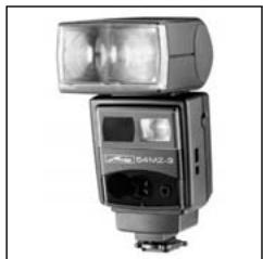
Photoelectronics
Plastics technology
Industrial electronics
Metz - always first class.

C E
707 47 0014.A1
D F NL GB I E
- MECABLITZ 58 AF-1 P digital
- Dosage flash/ambiance /P
- Mode spot beam "SB"
- Commutation metres - pieds (m / ft)
- Beep-function (Beep)
- Introduction
- Safety instructions
- Dedicated flash functions
- Preparing the flash unit for use
- Mounting the flash unit
- Mounting the flash unit on the camera
- Removing the flash unit from the camera
- Power supply
- Suitable batteries/rechargeable batteries
- Replacing batteries
- Switching the flash unit on and off
- Power Pack P76 (optional accessory)
- Auto OFF for the flash unit
- Display illumination
- Operating modes (mode menu)
- Adjusting procedure for flash operating modes
- TTL- flash mode
- Setting procedure:
- P-TTL flash mode
- ML / PMLfill-in flash mode
- Automatic flash mode
- Automatic flash mode
- Manual flash mode
- Set partial light output:
- Strobe flash mode
- Strobe number of flashes (N)
- Strobe flash frequency (f)
- Spot-beam mode
- Flash parameters (Parameter menu)
- Setting procedure for the flash parameters
- Main reflector position (Zoom)
- Flash exposure correction (EV)
- Manual partial light output (P)
- Special functions (Select menu)
- Setting procedure for the special functions
- Beep function (Beep)
- Acoustic signals after the flash unit has been turned on:
- Beep signals after taking a photograph:
- Beep signals when adjusting automatic mode settings:
- When the beep function is turned on, the symbol is also displayed on the LC display.
- Flash Bracketing Series (FB)
- When nFB0 is displayed, the flash bracketing series is deactivated.
- When the flash bracketing series is set, the correction value is always shown as a positive value!
- Flash bracketing series in the TTL/P-TTL flash mode
- Flash bracketing in automatic flash mode A
- Extended Zoom Mode (Zoom Ext)
- Example:
- Adjusting exposure format (Zoom Size)
- Cordless remote mode (Remote)
- Meter-Feet changeover (m/ft)
- Secondary reflector
- Modelling Light (ML)
- Auto OFF Function (Standby)
- KEYLOCK
- Activating the KEYLOCK function:
- Deactivating the KEYLOCK function
- Contrast
- Adjusting the setting
- Indicators in the camera viewfinder
- Flash-ready indicator
- Exposure control indicator in TTL flash mode
- Warning indicator
- Motor Zoom Reflector
- The following zoom positions are available:
- Automatic zoom adjustment
- Manual adjustment of the zoom position with AZoom
- Resetting to AZoom mode
- Wide-angle diffuser
- Flash techniques
- Bounce flash
- Bounce flash with a reflector card
- Bounce flash with secondary reflector
- Close-ups / macro shots
- Manual flash exposure corrections
- Dark subject in front of a bright background:
- Bright subject in front of a dark background:
- Flash readiness indication
- Automatic flash sync speed control
- Correct exposure indication
- Flash range indication
- Automatic adjustment of the flash range indication
- Flash synchronisation
- Normal synchronisation
- Second curtain synchronisation (REAR, 2nd curtain, SLOW2)
- Slow synchronisation / SLOW
- High-speed flash mode P-TTL-HSS
- Triggering control
- Preflash function for red-eye reduction
- Multi-zone AF measuring beam
- Wireless P-TTL - remote system
- Activating the remote flash mode as master
- Setting the parameters
- Activating the remote flash mode as Controller
- Activating the remote flash mode as Slave
- Deactivating the remote mode
- Care and maintenance
- Firmware updates
- Reset
- Flash capacitor forming
- Troubleshooting
- TILT" appears on the display
- "POWERPACK" appears on the display
- A battery warning appears on the display
- A battery symbol appears on the display
- The AF measuring beam of the flash unit is not activated.
- The reflector position is not automatically adjusted to the current zoom position of the lens.
- The sign for the zoom position of the reflector blinks in the display
- The secondary reflector cannot be activated, or no flash is triggered.
- The P-TTL or P-TTL-HSS flash modes cannot be called up and/or set on the flash unit.
- The secondary reflector flashes even though it is switched off.
- The setting for manual TTL/P-TTL flash exposure correction has no effect.
- Flash unit cannot be set for P-TTL wireless remote operation as the master flash unit.
- Automatic switching to the flash sync speed fails to occur.
- The shots have shadows in the bottom of the image.
- The shots are too dark.
- The shots are too bright.
- The flash parameters for ISO film speed and the aperture (f-stop) cannot be adjusted on the flash unit.
- The REAR mode cannot be activated on the flash unit.
- The contrast function mode cannot be set on the flash unit.
- Technical data
- Optional accessories
- Disposal of batteries
Brand : METZ
Model : MECABLITZ 58 AF-1 P DIGITAL
Category : External Flash