Drumfit Indoor Ultra Rider - Fitness Equipment CECOTEC - Free user manual and instructions
Find the device manual for free Drumfit Indoor Ultra Rider CECOTEC in PDF.


| Product type | Connected spinning indoor bike |
| Brand | Cecotec |
| Model | Drumfit Indoor Ultra Rider |
| Users | Adults and teenagers over 14 years old |
| Maximum user weight | 120 kg |
| Dimensions (L × W × H) | 128 × 52 × 118 cm |
| Net weight | 36 kg |
| Flywheel | 12 kg |
| Resistance | Continuously adjustable by knob |
| Transmission | Quiet belt |
| Connectivity | Wi-Fi, smartphone app (compatible with iOS and Android) |
| Console | Backlit LCD: time, distance, speed, calories, heart rate |
| Power supply | AC adapter (input 100–240 V, output 5 V/2 A) included |
| Adjustments | Handlebar and seat height adjustable |
| Safety | Emergency brake, adjustable stabilizers |
| Maintenance | Clean with a damp cloth, periodically check tightening and wear |
| Accessories | Tablet holder, bottle holder |
| Warranty | 2 years |
Frequently Asked Questions - Drumfit Indoor Ultra Rider CECOTEC
User questions about Drumfit Indoor Ultra Rider CECOTEC
0 question about this device. Answer the ones you know or ask your own.
Ask a new question about this device
Download the instructions for your Fitness Equipment in PDF format for free! Find your manual Drumfit Indoor Ultra Rider - CECOTEC and take your electronic device back in hand. On this page are published all the documents necessary for the use of your device. Drumfit Indoor Ultra Rider by CECOTEC.
USER MANUAL Drumfit Indoor Ultra Rider CECOTEC
Safety instructions 8
-
Parts and components 61
-
Before use 64
-
Assembly 65
-
Operation 67
-
Wi-Fi connectivity and mobile App 70
-
Cleaning and maintenance 71
-
Technical specifications 71
-
Recycling of electrical and electronic equipment 72
-
Technical support and warranty 72
-
Information on data stored by connected products in accordance with Regulation (EU)
2023/2854 ("Data Regulation") 72
-
Copyright 73
-
EU Declaration of Conformity 73
SOMMAIRE
EN · The coding in this manual is generic and applies to all code variants of the appliance.
Read the following instructions carefully before using the product. Keep this instruction manual for future reference or new users.
- Read the entire manual before assembling and using the machine. The product will only be safe if it is properly assembled, cared for and used correctly. It is your responsibility to make sure every user is informed about the warnings and precautions stated in this instruction manual.
- Before starting a training session, it is recommended that you consult your doctor if you have any adverse health or physical condition that may pose a risk to your safety or make it difficult to use the exercise bike properly. Your doctor's advice is essential if you are taking medication that affects your heart rate, blood pressure, or cholesterol level.
- Be aware of your body signals. Incorrect or excessive exercise can deteriorate your health. Stop exercising if you experience any of the following symptoms: pain, tightness in your chest, irregular heartbeat, extreme shortness of breath, dizziness, or nausea. If you experience any of these conditions, you should consult your doctor before continuing with your training.
- This machine can be used by children aged 14 years and above and persons with reduced physical, sensory, or mental capabilities or lack of experience and knowledge if they have been given supervision or instruction concerning the use of the machine in a safe way and understand the hazards involved. Children must not play with the appliance. Cleaning and user maintenance must not be carried out by children without supervision.
- Keep children and animals away from the assembling area,
as small parts could cause risk of suffocation if swallowed.
- Keep children and pets away from the machine. Do not allow children to use it and/or play with the machine. It is designed for adults only.
- Use the exercise bike on a solid, even surface with a protective cover for your floor or carpet.
- Ensure all screws and nuts are properly tightened before using the machine.
- The safety level of the machine can only be ensured through regular examination for damage or signs of wear and tear.
- Use the machine as indicated in this instruction manual. If you find any defective component while assembling or checking the machine, or if you hear any unusual noise coming from the equipment during use, stop using it. Do not use the equipment until the problem has been solved.
- Make sure you have enough space to lay out the parts before starting. Leave a free space of at least 0.6 m in front of all access areas of the machine in case of emergency. You can share the access areas with other machine nearby. Always ensure there are not any objects blocking the entrance and exit of the machine.

- Wear suitable clothing while using the machine. Avoid wearing loose clothing which may get caught in the equipment.
-
WARNING: this training machine is not suitable for high-precision purposes. This equipment is HC class.
-
WARNING: this machine operates by means of a flywheel. Be careful when in motion and ensure that it completely stops before getting down, as the inertia of the flywheel and pedals could cause injury to yourself or others.
- Maximum user weight: 130 kg.
- It is not recommended for outdoor use. This machine is designed for indoor use.
- This machine is designed for domestic use only and is not intended for bars, restaurants, farmhouses, hotels, motels, and offices.
- The machine is not suitable for therapeutic use.
- Care must be taken when lifting or moving the equipment so as not to injure your back.
- WARNING: the heart rate sensors may be inaccurate, as it is not a medical device. Sensors can give you estimated heart rate information. If you feel any discomfort, stop exercising immediately. It may be dangerous for your health. If it persists, go immediately to the nearest medical centre.
- If repairs are required, please consult your supplier for further information or contact Cecotec Customer Service.
- If any parts protrude from the machine, they may interfere with the user's movement.
INSTRUCTIONS DE SÉCURITÉ
Modo HRC (65% / 75% / 90%)
https://cecotec.es/es/information/declaration-of-conformity
1. PARTS AND COMPONENTS
Fig. 1
| No. | Description | Qty. |
| 1 | Console | 1 |
| 2 | Right handlebar upper cover | 1 |
| 3 | Phillips round head screw M5×10×∅10 | 2 |
| 4 | Square end cap J50×25 | 1 |
| 5 | Left handlebar upper cover | 1 |
| 6 | Right handlebar lower cover | 1 |
| 7 | Console bracket | 1 |
| 8 | Left handlebar lower cover | 1 |
| 9 | Phillips round head self-tapping screw ST3×16×∅5.6 | 6 |
| 10 | Handlebar | 1 |
| 11 | Washer D10×∅20×2.0 | 2 |
| 12 | Spring washer D10 | 2 |
| 13 | L-shaped knob | 1 |
| 14 | Socket head cap screw M10×30 | 2 |
| 15 | Left/right pedal | 2 |
| 16 | Left/right crank arm | 2 |
| 17 | Acorn nut | 4 |
| 18 | Spring washer D8 | 4 |
| 19 | Curved washer D8×∅20×2×R38 | 4 |
| 20 | Socket head cap screw ∅7.8×30, M6×15, S5 | 2 |
| 21 | Wheel | 2 |
| 22 | Washer D6×∅12×1.5 | 2 |
| 23 | Socket head cap screw M6×12×S5 | 2 |
| 24 | End cap ∅76 | 4 |
| 25 | Front stabiliser | 1 |
| 26 | Nut M8×H5.5×S14 | 4 |
| 27 | Adjustable foot | 4 |
| 28 | Main frame | 1 |
| 29 | Carriage bolt M8×90×20×20×H5 | 2 |
| 30 | Rear stabiliser | 1 |
| 31 | Spring-loaded adjustment knob | 1 |
| 32 | Saddle post | 1 |
| 33 | Not used | 2 |
| 34 | Saddle | 1 |
| 35 | Handlebar post | 1 |
| 36 | End cap | 4 |
| 37 | Not used | 1 |
| 38 | End cap | 2 |
| 39 | Hex flange nut M10×1.25×H7.5×S14 | 2 |
| 40 | Round decorative cover | 2 |
| 41 | Plastic plate decorative cover | 2 |
| 42 | Phillips round head self-tapping screw ST4.2×19×∅8 | 2 |
| 43 | Left/right chain cover | 2 |
| 44 | Connection column | 1 |
| 45 | Nylon nut M6×H6×S10 | 5 |
| 46 | Spring washer D6 | 4 |
| 47 | Shaft | 1 |
| 48 | Shaft bushing | 1 |
| 49 | Wave washer D20×∅26×0.3 | 1 |
| 50 | Belt pulley | 1 |
| 51 | Circular magnet | 1 |
| 52 | Hex bolt M6×16×S10 | 2 |
| 53 | Multi-V belt | 1 |
| 54 | Bearing | 2 |
| 55 | Seat post upper cover (L/R) | 1 set |
| 56 | Nylon nut M8×H7.5×S13 | 4 |
| 57 | Freewheel carriage bolt ∅10×35 M8×10×H6 | 1 |
| 58 | Bushing ∅10.2×∅15×8 | 1 |
| 59 | Freewheel adjustment plate | 1 |
| 60 | Arc freewheel | 1 |
| 61 | Not used | 0 |
| 62 | Not used | 0 |
| 63 | Not used | 0 |
| 64 | Washer D6×∅16×1.5 | 6 |
| 65 | Not used | 0 |
| 66 | Not used | 0 |
| 67 | Sensor | 1 |
| 68 | Phillips round head screw ST4.2×16×∅8 | 7 |
| 69 | Seat post lower right cover | 1 |
| 70 | EMS unidirectional flywheel | 1 |
| 71 | Circlip D20 | 1 |
| 72 | Not used | 0 |
| 73 | Not used | 0 |
| 74 | Phillips round head screw ST4.2×6×∅8 | 4 |
| 75 | Not used | 0 |
| 76 | Phillips round head self-tapping screw ST4.2×25×∅8 | 4 |
| 77 | Lower handlebar post cover (L/R) | 1 set |
| 78 | Connection tube lower cover | 1 |
| 79 | Phillips round head screw M5×10×∅10 | 2 |
| 80 | Seat post lower left cover | 1 |
| 81 | Stopper pin | 1 |
| 82 | Bushing | 1 |
| 83 | Connection tube upper cover | 1 |
| 84 | D-shaped bushing | 1 |
| 85 | Not used | 0 |
| 86 | Phillips countersunk screw M5×18×∅8 | 6 |
| 87 | Locking block | 1 |
| 88 | Rubber adhesive pad | 1 |
| 89 | Lower sliding block | 1 |
| 90 | Saddle cross-tube joint | 1 |
| 91 | Square end cap J40 | 2 |
| 92 | Rubber pad | 1 |
ENGLISH
| 93 | Stopper block | 1 |
| 94 | Phillips round head screw M4×12×∅7 | 2 |
| 95 | Limiter pin | 4 |
| 96 | Allen key S5 | 1 |
| 97 | Locking lever | 1 |
| 98 | Washer d6×∅14×2 | 1 |
| 99 | Not used | 0 |
| 100 | End cap | 2 |
| 101 | Packing tube | 2 |
| 102 | Power adapter | 1 |
| 103 | Not used | 0 |
| 104 | Extension cable 1 | 1 |
| 105 | Extension cable 2 | 1 |
| 106 | Pulse sensor cable | 2 |
| 107 | Countersunk socket screw M8×20, hex socket S5 | 2 |
| 108 | Bottle holder | 1 |
| 109 | Power extension cable | 1 |
| 110 | Printed Circuit Board (PCB) | 1 |
| 111 | Socket head cap screw M6×35, S5 | 1 |
| 112 | Washer M8×∅13×1.5 | 1 |
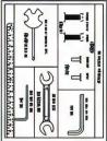
| A | Fixed spanner S13-14-15 | 1 |
| B | Allen key S8 | 1 |
| C | Allen key S5 | 1 |
| D | Cast spanner S13-S15 | 2 |
Note:
The graphics in this manual are schematic representations and may not exactly match the product.
2. BEFORE USE
- This appliance comes in a packaging designed to protect it during transport. Remove the appliance from its box. You can keep the original box and other packaging materials in a safe place to prevent damage to the appliance if you need to transport it in the future. If
you wish to dispose of the original packaging, make sure all items are recycled properly.
- Check that all parts and components are included and in good condition. If any of them are missing or damaged, please contact Cecotec's Official Technical Support Service immediately.
Box contents:
- Product
- Instruction manual
- Do not remove the product's serial number in order to keep proper traceability if technical assistance is required.
3. ASSEMBLY
Step 1
Fig. 3
Remove the packaging tube (101), carriage bolt M8×90×20×H5 (29), curved washer D8 (19), spring washer D8 (18) and acorn nut (17) from the main frame (28) using the L-shaped knob (13).
Attach the front stabiliser (25) and rear stabiliser (30) to the main frame (28) using the carriage bolt M8×90×20×H5 (29), curved washer D8×∅20×2×R38 (19), spring washer D8 (18) and acorn nut (17).
Step 2
Fig. 4
- Connect extension cable 1 (104) and extension cable 2 (105) as shown in Figure 4.
- Attach the console bracket (7) to the handlebar post (35) using the countersunk socket screw M8×20, hex socket S5 (107). Tighten with the Allen key S5 (C).
- Attach the handlebar (10) to the handlebar post (35) with the socket head cap screw M10×30 (14), spring washer D10 (12) and flat washer D10 (11). Tighten with the Allen key S8 (B).
Step 3
Fig. 5
- Remove the Phillips round head screw (3) from the console (1).
- Connect the console (1) cable—connectors (1a) and (1b)—to extension cable 1 (104) and pulse sensor cable (106), respectively. Ensure that the connectors are fully inserted and correctly locked in place.
ENGLISH
- Attach the console (1) to the console bracket (7) using the same screw removed in step 1. Check that no cables (104/106) are trapped between the console (1) and console bracket (7).
Step 4
Fig. 6
Attach the saddle (34) to the seat post (32) using the cast spanner S13 S15 (D). Before final tightening, adjust the position and angle of the saddle (34) to your preference and ensure it is firmly secured to the seat post (32).
Step 5
Fig. 7
• Install the left pedal (15) on the left crank arm (16). Start by hand and tighten anticlockwise. Complete the tightening with the fixed spanner S13-14-15 (A).
• Install the right pedal (15) on the right crank arm (16). Start by hand and tighten clockwise. Complete the tightening with the fixed spanner S13-14-15 (A).
Power supply:
Before beginning exercise, connect the power adapter (102) to the mains socket and to the equipment connector (via the power extension cable (109)). Fig. 8.
After completing your workout, disconnect the power adapter (102) from the mains socket.
Final inspection
- Do not use the equipment until assembly has been completed and proper operation has been verified according to this instruction manual.
- Inspect the machine to ensure that all fasteners are firmly tightened and that components are correctly assembled.
Moving the machine
Fig. 9
- Disconnect the power adapter (102) and, if applicable, the power extension cable (109).
- Use the transport handle to carefully tilt the machine until its weight rests on the wheels (21).
- Push the machine to the desired position.
- Carefully lower the machine until it is fully supported on the floor.
Note: The machine may be moved by one or more people depending on their physical
capabilities. Ensure that you and others are in suitable physical condition to move the machine safely.
Levelling the machine
Fig. 10
The machine must be levelled if the surface of your training area is uneven or if the base is slightly raised from the floor.
To adjust:
- Position the machine in your training area.
- Stand safely on the rear part of the "rail assembly" for approximately 20 seconds.
- Step down from the machine.
- Loosen the nuts M8×H5.5×S14 (26) and adjust the adjustable feet (27) until they all contact the floor.
- Adjust until the machine is level, then re-tighten the nuts M8×H5.5×S14 (26).
Safety note: Do not adjust the adjustable feet (27) to such a height that they may become detached or unscrew from the equipment. This could cause injury or damage. Ensure that the machine is level and stable before exercising.
4. OPERATION
Power-on and standby mode
When connecting the power adapter (102), the console (1) illuminates all LCD segments and emits a long beep. It then enters user selection mode. Note: if no signal is detected for approximately 256 seconds, the monitor enters standby mode. Press any button to reactivate the console (1).
User selection (USER)
- There are 5 users available. When powering on, use UP or DOWN to choose the desired user and press MODE to confirm.
Training mode selection
After confirming the user, press MODE to enter training mode selection.
• Use UP or DOWN to choose the mode and press MODE to confirm.
• Available modes: MANUAL, PROGRAM, WATT, HRC, USER.
Function buttons on the console (1)
. RESET
- Press and hold for more than 3 seconds to return to user selection.
ENGLISH
- In a setting screen, it clears/sets the active field to its initial value.
- During mode selection, it returns to user selection.
- In the Body Fat program, return to the main menu.
. MODE
- Confirm selections (mode, values).
. UP
- Navigate up (mode selection).
- Increases values (settings).
- During training, it increases the level of resistance.
. DOWN
- Navigate down (mode selection).
- Decreases values (adjustments).
- During training, the level of resistance decreases.
. ST/SP (Start/Stop)
- Starts or stops training.
- Start the body fat measurement in the Body Fat program.
- In USER mode selection, enter manual profile editing.
RECOVERY
o Initiates a 60-second pulse recovery test. Upon completion, the LCD displays F1-F6 (F1 = best recovery; F6 = worst).
Adjustment of training data
After confirming the user, select the training mode and confirm with MODE to enter the data setting.
• Available fields: TIME (time), DIST (distance), CAL (calories), THR (target heart rate).
- Important: only one of the three TIME or DIST or CAL fields can be preset per session (the rest count up). THR can be additionally preset when the mode allows it.
During training, adjust the resistance level with UP/DOWN.
MANUAL mode
-
Select MANUAL and press MODE to select the field to be set (TIME, DIST, CAL, THR). Each field flashes; adjust with UP/DOWN and confirm with MODE.
• Range and behaviour: -
TIME: 1:00–99:00 (default 0:00; step ±1:00). Without preset, counts upwards; with preset, counts down to 0.
- DIST: 1.0–999.0 (default 0.0; step ±1.0). Without preset, counts upwards; with preset, counts down to 0.
-
CAL: 10–9990 (default 0; step ±10). Without preset, counts upwards; with preset, counts down to 0.
-
WATT: 25–400 (default 25; step ±5). Informational only in MANUAL; does not regulate automatically.
- THR: 60–220 (default 90; step ±1). If the set range is exceeded, the monitor warns.
Acoustic warning: when the preset value reaches 0, a beep sounds.
PROGRAM mode (preset programs)
There are 12 preset programs and 1 Body Fat program. Each preset program has 16 load segments; available resistance levels are 1–32.
- Select a program with UP/DOWN, press MODE and choose the field to be preset (TIME, DIST, CAL, THR if applicable). Adjust with UP/DOWN and confirm with MODE.
You can change the resistance level during exercise with UP/DOWN.
The bicycle beeps when the preset value (if applicable) reaches 0.
Body Fat Program
- Access: selection within PROGRAM with UP/DOWN or by means of the dedicated Body Fat key.
- Adjust personal data: age, sex, height and weight. Each field flashes; adjust with UP/DOWN and confirm with MODE.
Measurement: press ST/SP and hold the hand-held pulse sensors. Continue at rest until the result is displayed.
WATT mode
- Select WATT and press MODE to adjust TIME, WATT, DIST, CAL, THR. Adjust with UP/DOWN and confirm with MODE.
During training, the monitor automatically adjusts the resistance level to maintain the preset WATT value based on your pedalling speed.
The machine beeps when the preset value reaches 0 (if applicable).
THR mode (personalized target heart rate)
- Select THR and press MODE to preset one of TIME or DIST or CAL and, in addition, THR. Adjust with UP/DOWN and confirm with MODE.
During exercise, hold the hand-held pulse sensors. The monitor automatically modifies the level to reach the set THR. - Control logic: if the measured pulse is below the THR, the level increases by 1 every 30 seconds; if above, the level decreases by 1 every 20 seconds.
The bicycle beeps when the preset value (if applicable) reaches 0.
HRC Mode (65% / 75% / 90%)
- Select 65%, 75% or 90% and press MODE to preset TIME, DIST or CAL. Adjust with UP/DOWN and confirm with MODE.
• Automatic cardiac targeting:
- 65 % TARGET H.R = 65 % × (220 - AGE )
- 75 % TARGET H.R = 75 % × (220 - AGE )
ENGLISH
- 90 % TARGET H.R = 90 % × (220 - AGE )
During exercise, hold the hand pulse sensors; the monitor automatically adjusts the level to approach the target.
The machine beeps when the preset value reaches 0 (if applicable).
USER mode (user program)
• Allows you to define your own load profile.
- Press MODE: the first load segment flashes; adjust the level with UP/DOWN and confirm with MODE to proceed to the next segment. Repeat until all 20 segments are completed.
- Then press MODE to select the field to be preset (TIME or DIST or CAL) and, if applicable, THR. Adjust with UP/DOWN and confirm with MODE.
During training, the level can also be adjusted manually with UP/DOWN.
The bicycle beeps when the preset value (if applicable) reaches 0.
RECOVERY function (recovery test, 60 seconds)
With the exercise stopped, press RECOVERY and hold the pulse sensors. After 60 seconds, F1-F6 is displayed (F1 = best).
General notes
During any training, you can adjust the resistance with UP/DOWN.
If stopped with ST/SP, press ST/SP again to resume.
If the unit goes to sleep, press any button to reactivate the Display (1).
5. WI-FI CONNECTIVITY AND MOBILE APP
a. Kinomap
Search, download and install the Kinomap app from the Apple Store or Google Play depending on your mobile phone system.
1) Access the app and click on the "More" page.
2) Select the option "Add new training machine".
3) Select the type of equipment "stationary bike".
4) Then click on the device or on "Cecotec" to pair the machine.
5) Look for videos to start the training.
b. Zwift
Search, download and install the Zswift APP from the Apple Store or Google Play depending on your mobile phone system.
1) Create an account and access the APP.
2) Activate the product sensors and Bluetooth on your phone or tablet.
3) Select the type of equipment "stationary bike".
4) Then click on the power or speed source icon.
5) Search route to start training.
Please note that it is not possible to include a complete application guide in this manual, as it is a free third-party application and is updated continuously.
For more information about the app, please refer to the instructions found within the specific application or in the Google PlayStore or AppStore.
6. CLEANING AND MAINTENANCE
- Periodically lubricate moving parts to prevent premature wear.
- Inspect and tighten all parts before use. If any part is damaged, replace it immediately and do not use the machine until it is in perfect condition.
- Clean the machine with a slightly damp cloth and non-abrasive detergent. Do not use solvents.
- Do not try to repair the machine by yourself. If you experience any difficulties with assembly, operation or believe parts are missing, please contact your dealer or Cecotec's Official Technical Support Service.
Warning:
The frequency of cleaning and maintenance depends on usage frequency and intensity.
7. TECHNICAL SPECIFICATIONS
Product: Drumfit Indoor Ultra Rider
Product reference: EU01_122643
Maximum user weight: 130 kg
Class: HC
Voltage: 220 - 240 V
Frequency: 50 – 60 Hz
Power: 400 W
ENGLISH
Technical specifications may change without prior notice to improve product quality. Made in China | Designed in Spain
8. RECYCLING OF ELECTRICAL AND ELECTRONIC EQUIPMENT

This symbol indicates that, according to the applicable regulations, the product and/or battery must be disposed of separately from household waste. When this product reaches the end of its shelf life, you should dispose of the batteries/accumulators and take them to a collection point designated by the local authorities.
For detailed information on how to properly dispose of electrical and electronic equipment and/or the corresponding batteries, consumers should contact their local authorities.
Information regarding national packaging recycling systems and their marking can be found on our website.
Compliance with the above guidelines will help protect the environment.
9. TECHNICAL SUPPORT AND WARRANTY
Cecotec shall be liable to the end user or consumer for any lack of conformity that exists at the time of product delivery under the terms, conditions and deadlines established by applicable regulations.
Repairs should be carried out by qualified personnel.
If at any moment you detect any problem with your product or have any doubt, do not hesitate to contact the official Cecotec Technical Support Service at +34 96 321 07 28.
10. INFORMATION ON DATA STORED BY CONNECTED PRODUCTS IN ACCORDANCE WITH REGULATION (EU) 2023/2854 ("DATA REGULATION")
Cecotec's connected products and related services are those that generate different data and information during use. In accordance with the provisions of the Data Regulation, through this document Cecotec provides you with information about your rights concerning the data generated and about how to access such data.
This right allows you to use the data for any lawful purpose, including, among others, product and/or service optimisation or contracting post-sale services with third parties.
As a user, you may exercise your right of access, within the limits provided for by the Data
Regulation, through the email address data.act@cecotec.es. To protect the generated data—and in order to prevent fraud or identity theft—CECOTEC may require additional information to verify your status as a user.
Data is stored for a determined period of time.
11. COPYRIGHT
The intellectual property rights over the texts in this manual belong to CECOTEC INNOVACIONES, S.L. All rights reserved. The content of this publication may not, either in part or in its entirety, be reproduced, stored in a retrieval system, transmitted or distributed by any means (electronic, mechanical, photocopying, recording or similar) without prior authorisation from CECOTEC INNOVACIONES, S.L.
12. EU DECLARATION OF CONFORMITY
CE Cecotec Innovaciones hereby declares that this indoor exercise bike, model EU01_122643 – Drumfit Indoor Ultra Rider, is in conformity with the Radio Equipment Directive 2014/53/EU.
The full text of the EU Declaration of Conformity can be found on the following website: https://cecotec.es/es/information/declaration-of-conformity
1. PIÈCES ET COMPOSANTS
Image 1:
https://storececotec.de/de/information/declaration-of-conformity1. Parti e componenti
1. PARTI E COMPONENTI
Figura 1:
5. CONNETTIVITÀ WI-FI E APP
a. Kinomap
Modo HRC (65% / 75% / 90%)
- 65% TARGET H.R = 65% × (220 - IDADE)
- 75% TARGET H.R = 75% × (220 - IDADE)
- 90% TARGET H.R = 90% × (220 - IDADE)
https://cecotec.pt/pt/information/declaration-of-conformity
1. ONDERDELEN EN COMPONENTEN
Afbeelding 1:
HRC-modus (65% / 75% / 90%)
Product: Drumfit Indoor Ultra Rider
Productreferentie: EU01_122643
https://cecotec.es/es/information/declaration-of-conformity
1. CZĘŚCI I KOMPONENTY
Rysunek 1:
- 90% TARGET H.R = 90% × (220 - WIEK)
https://cecotec.es/es/information/declaration-of-conformity
1. PARÇALAR VE BILEŞENLER
Şekil 1:
https://cecotec.es/es/information/declaration-of-conformity
1. PECES I COMPONENTS
Figura 1:
Mode PROGRAM (programs preestablerts)
Mode HRC (65% / 75% / 90%)
https://cecotec.es/ca/information/declaration-of-conformity
HRC mód (65% / 75% / 90%)
https://cecotec.es/es/information/declaration-of-conformity

Fig./Img./Abb./Afb./Rys.1
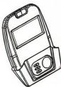 |  |  | |
| #1 Display 1PC | #7 Display Post 1PC | #10 Handlebar 1PC | |
 | 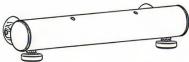 |  | |
| #15 Pedal 1pair | #25 Front Stabilizer Assembly 1PC | #30 Rear Stabilizer Assembly 1PC | |
 | 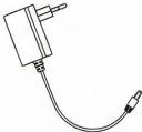 |  | |
| #54 Saddle 1PC | #102 Adaptor 1PC | Bilster Card 1PC | |
| [D6X0] | 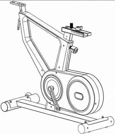 | ||
| #108 aluminum bottle holder 1PC | |||
| #28 Mainframe 1PC | |||
Fig./Img./Abb./Afb./Rys.2
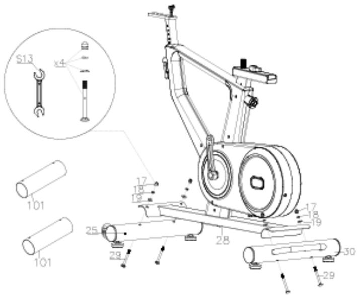
Fig./Img./Abb./Afb./Rys. 3

Fig./Img./Abb./Afb./Rys. 4

Fig./Img./Abb./Afb./Rys. 5

Fig./Img./Abb./Afb./Rys. 6

Fig./Img./Abb./Afb./Rys.7
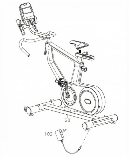
Fig./Img./Abb./Afb./Rys. 8
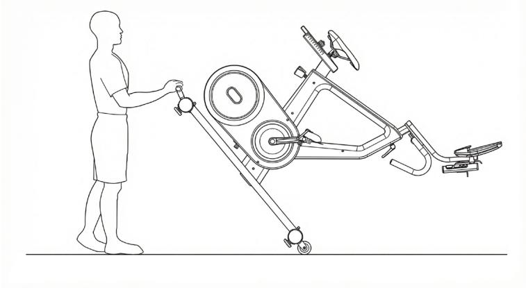
Fig./Img./Abb./Afb./Rys. 9

Fig./Img./Abb./Afb./Rys. 10
www.cecotec.es

- SOMMAIRE
- INSTRUCTIONS DE SÉCURITÉ
- PARTS AND COMPONENTS
- ENGLISH
- BEFORE USE
- BOX CONTENTS
- ASSEMBLY
- STEP 4
- FIG. 6
- STEP 5
- FIG. 7
- POWER SUPPLY
- FINAL INSPECTION
- MOVING THE MACHINE
- FIG. 9
- LEVELLING THE MACHINE
- OPERATION
- PROGRAM MODE (PRESET PROGRAMS)
- BODY FAT PROGRAM
- WATT MODE
- THR MODE (PERSONALIZED TARGET HEART RATE)
- HRC MODE (65% / 75% / 90%)
- WI-FI CONNECTIVITY AND MOBILE APP
- CLEANING AND MAINTENANCE
- TECHNICAL SPECIFICATIONS
- RECYCLING OF ELECTRICAL AND ELECTRONIC EQUIPMENT
- TECHNICAL SUPPORT AND WARRANTY
- INFORMATION ON DATA STORED BY CONNECTED PRODUCTS IN ACCORDANCE WITH REGULATION (EU) 2023/2854 ("DATA REGULATION")
- COPYRIGHT
- EU DECLARATION OF CONFORMITY
- PIÈCES ET COMPOSANTS
- PARTI E COMPONENTI
- CONNETTIVITÀ WI-FI E APP
- ONDERDELEN EN COMPONENTEN
- HRC-MODUS (65% / 75% / 90%)
- CZĘŚCI I KOMPONENTY
- PARÇALAR VE BILEŞENLER
- PECES I COMPONENTS
Brand : CECOTEC
Model : Drumfit Indoor Ultra Rider
Category : Fitness Equipment