
SM180 - Safety valve HONEYWELL - Free user manual and instructions
Find the device manual for free SM180 HONEYWELL in PDF.
| Product type | Diaphragm safety valve |
| Brand | Honeywell |
| Model | SM180 |
| Use | Protection of closed solar installations with intrinsic safety |
| Permissible fluid | Water or water-glycol mixture according to VDI 2035, liquids of groups 1 and 2 compatible |
| Set pressure | Factory set: 2.5 / 3.0 / 4.0 / 6.0 / 8.0 or 10.0 bar |
| Service temperature | -20 °C to +160 °C |
| Inlet connection (female thread) | Rp 1/2" or Rp 3/4" |
| Outlet connection (female thread) | Rp 1/2", Rp 3/4" or 1" |
| Body material | Brass |
| Diaphragm | Hot water resistant elastomer |
| Setting spring | Spring steel |
| Safety cap | High-quality plastic |
| Mounting position | Horizontal, safety cap facing upwards |
| Max. tightening torque of connections | 18 Nm |
| Inspection | Every 6 months (check of response capability) |
| Maintenance | Annually by a professional |
| Standards | Pressure Equipment Directive (PED), DIN 1988 part 8 |
| Delivery contents | Safety valve (body, spring, diaphragm, cap) |
| Warranty | Refer to general terms and conditions of sale |
Frequently Asked Questions - SM180 HONEYWELL
User questions about SM180 HONEYWELL
0 question about this device. Answer the ones you know or ask your own.
Ask a new question about this device
Download the instructions for your Safety valve in PDF format for free! Find your manual SM180 - HONEYWELL and take your electronic device back in hand. On this page are published all the documents necessary for the use of your device. SM180 by HONEYWELL.
USER MANUAL SM180 HONEYWELL
Keep instructions for later use!
Diaphragm safety valve
- Safety Guidelines 6
- Functional description 6
- Application 6
- Technical data 6
- Options 6
- Scope of delivery 6
- Assembly 7
- Commissioning 7
- Maintenance 8
- Disposal 8
F
- Follow the installation instructions.
- Use the appliance
according to its intended use - in good condition
with due regard to safety and risk of danger. - Note that the appliance is exclusively for use in the applications detailed in these installation instructions. Any other use will not be considered to comply with requirements and would invalidate the warranty.
- Please take note that any assembly, commissioning, servicing and adjustment work may only be carried out by authorized persons.
- Immediately rectify any malfunctions which may influence safety.
2. Functional description
Diaphragm safety valves of this type are directacting safety valves in which the disc is pushed up by the pressure from the system against a spring which is holding the valve closed. If the opening force exceeds the force exerted by the spring, then the valve disc is lifted off the valve seat and the valve discharges the medium. In accordance with the requirements of the standard, the full discharge capacity of the valve will be achieved when the system pressure climbs to no more than 10% above the set pressure of the valve. Full shutoff must be achieved if the system pressure falls to below 80% of the nominal set pressure of the valve. For valves rated up to 3.0 bar, the closing pressure can be taken as 0.6 bar minimum.
3. Application
To protect closed solar systems.
Medium Water or glycol-water mixture, according to VDI 2035
Liquids of the fluid group 1 and 2 (pressure device guideline, item 9) which do not affect the materials used.
4. Technical data
| Installation position | Horizontal with safety cap point-up |
| Opening pressure | Factory preset to 2.5, 3.0, 4.0, 6.0, 8.0 or 10.0 bar Subsequent alteration of the setting is not permitted and is impossible without destroying the security cap |
Operating temperature -20 °C...+160 °C
Connection size Internal thread on inlet 1 / 2^ 3 / 4^ Internal thread on outlet 1 / 2^ 3 / 4^ 1"
Valve size is defined by the size of the inlet connection
5. Options
| OS.-No. | Set pres-Connection | ||
| sure | size Inlet | size Outlet | |
| SM180- 1/2ZA2.5 | 2.5 bar | Rp1/2" IG | Rp1/2" IG |
| SM180- 1/2ZA3.0 | 3.0 bar | Rp1/2" IG | Rp1/2" IG |
| SM180- 1/2ZA4.0 | 4.0 bar | Rp1/2" IG | Rp1/2" IG |
| SM180- 1/2ZA6.0 | 6.0 bar | Rp1/2" IG | Rp1/2" IG |
| SM180- 1/2ZA8.0 | 8.0 bar | Rp1/2" IG | Rp1/2" IG |
| SM180- 1/2ZA10.0 | 10.0 bar | Rp1/2" IG | Rp1/2" IG |
| SM180- 1/2A2.5 | 2.5 bar | Rp1/2" IG | Rp3/4" IG |
| SM180- 1/2A3.0 | 3.0 bar | Rp1/2" IG | Rp3/4" IG |
| SM180- 1/2A4.0 | 4.0 bar | Rp1/2" IG | Rp3/4" IG |
| SM180- 1/2A6.0 | 6.0 bar | Rp1/2" IG | Rp3/4" IG |
| SM180- 1/2A8.0 | 8.0 bar | Rp1/2" IG | Rp3/4" IG |
| SM180- 1/2A10.0 | 10.0 bar | Rp1/2" IG | Rp3/4" IG |
| SM180- 3/4ZA2.5 | 2.5 bar | Rp3/4" IG | Rp3/4" IG |
| SM180- 3/4ZA3.0 | 3.0 bar | Rp3/4" IG | Rp3/4" IG |
| SM180- 3/4ZA4.0 | 4.0 bar | Rp3/4" IG | Rp3/4" IG |
| SM180- 3/4ZA6.0 | 6.0 bar | Rp3/4" IG | Rp3/4" IG |
| SM180- 3/4ZA8.0 | 8.0 bar | Rp3/4" IG | Rp3/4" IG |
| SM180- 3/4ZA10.0 | 10.0 bar | Rp3/4" IG | Rp3/4" IG |
| SM180- 3/4A2.5 | 2.5 bar | Rp3/4" IG | Rp1" IG |
| SM180- 3/4A3.0 | 3.0 bar | Rp3/4" IG | Rp1" IG |
| SM180- 3/4A4.0 | 4.0 bar | Rp3/4" IG | Rp1" IG |
| SM180- 3/4A6.0 | 6.0 bar | Rp3/4" IG | Rp1" IG |
| SM180- 3/4A8.0 | 8.0 bar | Rp3/4" IG | Rp1" IG |
| SM180- 3/4A10.0 | 10.0 bar | Rp3/4" IG | Rp1" IG |
6. Scope of delivery
The safety valve comprises:
Angled housing
- Adjustment spring
- Diaphragm
- Security cap with part label
7. Assembly
7.1 Installations Guidelines
-
Mount the safety valve at the highest point of the heat generator or in its immediate vicinity on the flow line
-
The installation must be carried out so that: o no shut-off fittings, restrictions or strainers are located between safety valve and heat generator o good access is provided for service and maintenance
o that the safety valve is positioned above the heat generator
o that between the safety valve and heat exchanger a max. 1 m long straight connection line with the size of the inlet diameter is installed
- The safety valve must be mounted so that in its installed condition no external forces act on it
- The discharge line must be performed to the size of the safety valve outlet diameter and may not have more than 2 elbows and or be longer than 2m
- The discharge line must be installed with an incline
7.2 Assembly instructions

The safety valve may not be overheated through welding and soldering work on the system. Install the safety valve only after these tasks are completed.
- Thoroughly flush pipework
- Install the membrane safety valve
o Tighten the connections with max. 18 Nm when joining. Cracks may form in the material when tighten to strongly which may cause leaks in the system.
o Installation in horizontal pipe with safety cap pointing up
o Note flow direction
o Install without tension or bending stresses
- Install discharge line
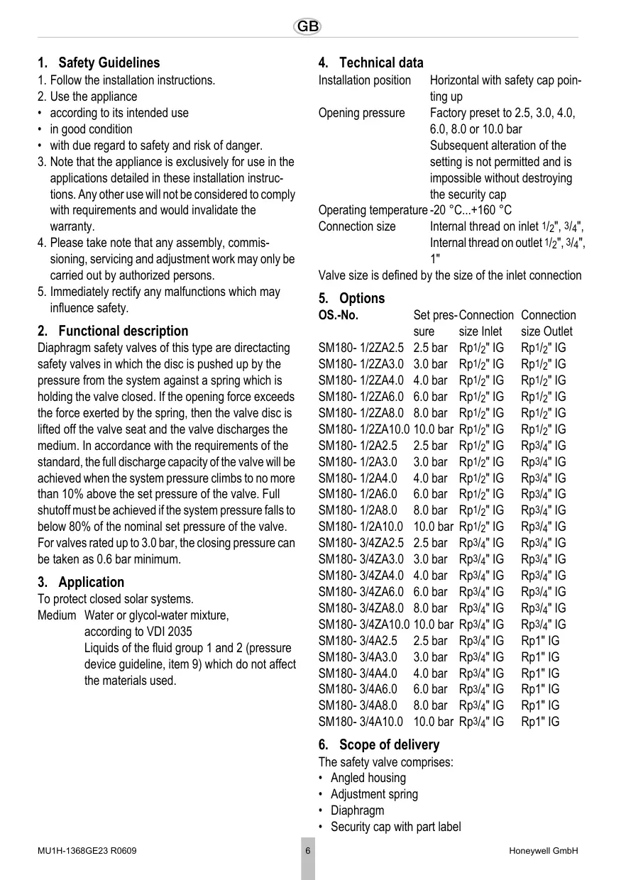
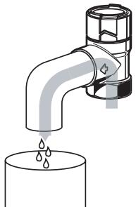
Risk of scaling through hot liquid escaping from the discharge opening. Route discharge line so that neither personal injuries nor property damage can be caused by discharged fluid.
The discharge opening is marked by an arrow on the valve body
4. Guide the outlet of the discharge line into a drain or container which can accept the total content of the system.

If there is a risk that the discharge line becomes clogged or can freeze, interrupt the discharge line, e.g. by a funnel. The discharge line of the funnel must have twice the cross-section of the safety valve intake
8. Commissioning
- Mount a warning sign readily visible near the discharge line or on the safety valve with the following text:
While heating, water must escape from the discharge line for safety reasons. Do not close! - Make sure that all water connections are tight
- We recommend flushing the supply line before commissioning the plant
9. Maintenance
In accordance with DIN 1988, Part 8, the following operations should be carried out regularly. A planned maintenance scheme is recommended.
9.1 Inspection
To be carried out by an installation company or the operator.
Frequency: every 6 month
Risk of scaling through hot liquid escaping from the discharge opening.
Function check by verifying the response: While the system is operating, briefly open the safety valve by turning the cap. After closing the cap the valve must close again the backed up water drain completely.
9.2 Maintenance
To be carried out by an installation company Interval: once a year Risk of scaling through hot liquid escaping from the discharge opening.
If a malfunction is detected, a repair can be attempted by opening and closing the cap several times. A replacement is necessary if this action is not successful.
10. Disposal
- Brass housing
Spring steel adjustment spring
High grade synthetic material security cap - Hot water resistant elastomer diaphragm

Observe the local requirements regarding correct waste recycling/disposal!
SM180- 1/2A4.0 4,0 bar Rp1/2" IG Rp3/4" IG
SM180- 1/2A6.0 6,0 bar Rp1/2" IG Rp3/4" IG
SM180- 1/2A8.0 8,0 bar Rp1/2" IG Rp3/4"IG
SM180- 1/2A10.0 10,0 bar Rp1/2" IG Rp3/4" IG
SM180-3/4ZA2.5 2,5 bar Rp3/4"IG Rp3/4"IG
SM180-3/4ZA3.0 3,0 bar Rp3/4" IG Rp3/4" IG
SM180-3/4ZA4.0 4,0 bar Rp3/4" IG Rp3/4" IG
SM180-3/4ZA6.0 6,0 bar Rp3/4" IG Rp3/4" IG
SM180-3/4ZA8.0 8,0 bar Rp3/4" IG Rp3/4" IG
SM180-3/4ZA10.0 10,0 bar Rp3/4"IG Rp3/4"IG
SM180-3/4A2.5 2,5 bar Rp3/4"IG Rp1"IG
SM180-3/4A3.0 3,0 bar Rp3/4"IG Rp1"IG
SM180-3/4A4.0 4,0 bar Rp3/4"IG Rp1"IG
SM180-3/4A6.0 6.0 bar Rp3/4"IG Rp1"IG
SM180-3/4A8.0 8.0 bar Rp3/4"IG Rpl"IG
SM180-3/4A10.0 10.0 bar Rp3/4"IG Rp1"IG
SM180- 1/2A4.0 4,0 bar Rp1/2" IG Rp3/4" IG
SM180- 1/2A6.0 6,0 bar Rp1/2" IG Rp3/4" IG
SM180- 1/2A8.0 8,0 bar Rp1/2" IG Rp3/4"IG
SM180- 1/2A10.0 10,0 bar Rp1/2" IG Rp3/4" IG
SM180-3/4ZA2.5 2,5 bar Rp3/4" IG Rp3/4" IG
SM180-3/4ZA3.0 3,0 bar Rp^3 / 4 IG Rp^3 / 4 IG
SM180-3/4ZA4.0 4,0 bar Rp^3 / 4 IG Rp^3 / 4 IG
SM180-3/4ZA6.0 6,0 bar Rp3/4"IG Rp3/4"IG
SM180-3/4ZA8.0 8,0 bar Rp3/4"IG Rp3/4"IG
SM180-3/4ZA10.0 10,0 bar Rp3/4"IG Rp3/4"IG
SM180-3/4A2.5 2,5 bar Rp3/4"IG Rp1"IG
SM180-3/4A3.0 3,0 bar Rp3/4"IG Rp1"IG
SM180-3/4A4.0 4,0 bar Rp3/4"IG Rp1"IG
SM180-3/4A6.0 6.0 bar Rp3/4"IG Rp1"IG
SM180-3/4A8.0 8.0 bar Rp3/4"IG Rp1"IG
SM180-3/4A10.0 10.0 bar Rp3/4"IG Rp1"IG
6. Fornitura
Pa3Mepom KlaIaHa JbIeTcpa3Mep npCoeDInHnHa HxOe
5.Obem noctabkn
| № apt. | Давлиения начала сраватыва няя | Раимер приноевский приноевский Я на ВхODE | Раимер Я на ВхODE |
| SM180- 1/2ZA2.5 | 2,5 бap | Rp1/2" B/pe3. | Rp1/2" B/pe3. |
| SM180- 1/2ZA3.0 | 3,0SBAP | Rp1/2" B/pe3. | Rp1/2" B/pe3. |
| SM180- 1/2ZA4.0 | 4,0SBAP | Rp1/2" B/pe3. | Rp1/2" B/pe3. |
| SM180- 1/2ZA6.0 | 6,0SBAP | Rp1/2" B/pe3. | Rp1/2" B/pe3. |
| SM180- 1/2ZA8.0 | 8,0SBAP | Rp1/2" B/pe3. | Rp1/2" B/pe3. |
| SM180- 1/2ZA10.0 | 10,0SBAP | Rp1/2" B/pe3. | Rp1/2" B/pe3. |
| SM180- 1/2A2.5 | 2,5SBAP | Rp1/2" B/pe3. | Rp3/4" B/pe3. |
| SM180- 1/2A3.0 | 3,0SBAP | Rp1/2" B/pe3. | Rp3/4" B/pe3. |
| SM180- 1/2A4.0 | 4,0SBAP | Rp1/2" B/pe3. | Rp3/4" B/pe3. |
| SM180- 1/2A6.0 | 6,0SBAP | Rp1/2" B/pe3. | Rp3/4" B/pe3. |
| SM180- 1/2A8.0 | 8,0SBAP | Rp1/2" B/pe3. | Rp3/4" B/pe3. |
| SM180- 1/2A10.0 | 10,0SBAP | Rp1/2" B/pe3. | Rp3/4" B/pe3. |
| SM180- 3/4ZA2.5 | 2,5SBAP | Rp3/4" B/pe3. | Rp3/4" B/pe3. |
| SM180- 3/4ZA3.0 | 3,0SBAP | Rp3/4" B/pe3. | Rp3/4" B/pe3. |
| SM180- 3/4ZA4.0 | 4,0SBAP | Rp3/4" B/pe3. | Rp3/4" B/pe3. |
| SM180- 3/4ZA6.0 | 6,0SBAP | Rp3/4" B/pe3. | Rp3/4" B/pe3. |
| SM180- 3/4ZA8.0 | 8,0SBAP | Rp3/4" B/pe3. | Rp3/4" B/pe3. |
| SM180- 3/4ZA10.0 | 10,0SBAP | Rp3/4" B/pe3. | Rp3/4" B/pe3. |
| SM180- 3/4A2.5 | 2,5SBAP | Rp3/4" B/pe3. | Rp1" B/pe3. |
| SM180- 3/4A3.0 | 3,0SBAP | Rp3/4" B/pe3. | Rp1" B/pe3. |
| SM180- 3/4A4.0 | 4,0SBAP | Rp3/4" B/pe3. | Rp1" B/pe3. |
| SM180- 3/4A6.0 | 6,0SBAP | Rp3/4" B/pe3. | Rp1" B/pe3. |
| SM180- 3/4A8.0 | 8,0SBAP | Rp3/4" B/pe3. | Rp1" B/pe3. |
| SM180- 3/4A10.0 | 10,0SBAP | Rp3/4" B/pe3. | Rp1" B/pe3. |
6.ObbemIOCTaBKn
PpeoXpaHnteJbHbI KJIanaH COCTOHT I3:
Kopnyc ByrIIOBOM mCOnJHHeHm
- Perynipyuem npykuHa
- MembpaHa
- Празхантейьн Колпачок схаразсеростник DeTaJIи
7. MoHTaX
7.1PykoBoDCTBO IO yctaHOBKe
CMOHTIPOBAbI ppeOxpaHITeNbHbI KlaanHa cAmoB BerXHeN ToUKe rHePaTOpA TePnAn INI B HeOpCeDCTBeHHo6I3n OToNaIOuSeJINHN
OcuyeCTBnTb yCTaHOBky TaK, YTO6bl: oMeJy npEdoxpaHITeNbHbIM KlaanAHOM n reHepaTOPm TeNla He 6bIIO 3aOpHoi apMaTybl, cyKeHNI CNT oOecneuBaIacb xopoOoee yDo6CTBO DoCTyna dIra IPOBeDEHnpeMOHThBIX pa6OT n pa6OT no TEXHnueckOMy OcbLynXBAHIO o npEdoxpaHITeNbHBI Klaanah pAcNoIarlanC hAD rHeHepaTOPm TeNla oMeJy npEdoxpaHITeNbHbIM KlaanAHOM n reHepaTOPom 6bla ycTaHOBNeHa npJam coEdinHITeNbHa JINnA DnHnOH He 60Je e 1 M pa3MepOM BXODHOrO nonepeuHOrO ceEHnIA
- PnpdoxpanHeIbHbI KJIanaH DoJIKeH 6blYcTaHOBJIeH TAK, YTO6bl BO BCTpoEHHom COCTOHN Ha Hero He DeIeCTBOBaJIIN BHeUHHe CIIbl
BbIyucHoi Tpy6oNpOBoDdoJIoJIeH 6bITb BblOnJIeH no pa3Mepy BbIXoHOrO nonepueHoro CeYeHn IpeoXpaHInTeNbHO rKlanaHa n He doJIoJIeH ImEt bOJe e 2 KoJIeH, a TaKKe He doJIoJIeH 6bITb DInHoH 6oJIe e 2 M
BbIyucKHO Tpy6oPBOOД OJKeH 6bITb npoloxeH cHaKIOHOM
3.YCTaHOBt BbInyCKHoT py6oPoBOd
Onachoctb noIyueHnOxOROBOT BbIXoJaSei,TopraeJxNIOKCTNa H BbIyCKHOM OTBepCTNI. YIoxNtB BblNyckHO Tpy6OpBOPOD TaK, UTObblBixOJaA JxNIOKCTb He CMOrla npuHNITb BpeJ IIOdAM NIN CEHHOMy IMUyEcTBy.
BbInyckHoe OTBepCTne OTMeueHo CTpeJIkoHa Kopnyce KnaanaHa
4. HanpaBntb BixOJ noTOK BblyckHOro Tpy60npoBOda B dpeHaxKbI CTOK ININ EMKOCTb, CnOC6HyIO BmecTNTB BECb 0bEm yctaHOKn.
B cnyuae BO3HNKHOBEHnO nAcHOCtN 3aKyopNBaHnI nn 3aMep3aHnBbInyckHOro Tpy60npOBoJa Heo6XoDMO OcyuecTBnTb pa3beDnHeHne BblyckHOro Tpy60npOBoJa (HaNPmEp, BOPOHKn).Y BblnyckHOro Tpy60npOBoJa BOPOHKn DoJIxHo 6bItb DBoHoe nonepueHoe ceYeHne BXoJa npedoxpaHnTeJbHoro KlaNaHa
8. BvoB B 3KcnplyaTaunio
- Pa3mecTntb B6IIN3n BblnyckHOro Tpy60npoBOda nIIN Ha npdeOxpaHITeNBOM KlaPAnHe XopoSoB BVIMyU TObLIuKcY c yka3aHHe CneDyHOJIero COdepXaHIny:
BoBpemrOToPJIeHnI3coo6paJxHnI 6e3OnaNCHOTnI3BbIpyCKHOro Tpy6OpBOVaIOJIXHa BbIXOHTb BOJa. He 3akynopnbTb!
2.Пюверпь ВОДОнрОНЦаEMOCТ BCEXnpICOeINHEnH BODI
3.Перед ВВОДOMВЗКСПУАТAUHUGYCTAHOBKNMbI peKOMeHdYeEM pOmbyTb BOДОПРОВODYCETb
9. YxoJ
BcootBeCTBnC DIN1988, Yactb 8 Heo6xOIMO peryIaRHOe npOBeHne npBVeEHHbIX daJeempeopnpTm. Mbl peKOMeHNyEM 3akNIOHTb DOROBOP TexHnueCKOrO 06cnyXnBaHnM MeJdy 3KcIIpyaTaUOnHHNKOM m PpeDpNpTNeM, OcyIeCTBnBUnm yCTaHOBVk.
9.1 INHcneKUa

IIOBOUNTCMOHTaXHoI opraHn3aUeI INN BnaJeJIbCeM
INHTepBaI:KaKdIbe6MecraeB
Onachoctb noIyehnO xKorOBOT
BbIXOJaIeI, TOpAYe JKnIOKCTN Ha BbIyCKHOM OTBepCTNI.
KoHTpOJI npaBnJIbHocTnФyHKUHOHropOBaHnnyTem npOBepKn cNoCobHocTn cpa6aTbIBaHn:BoBpeM pa60tby yCTaHOBKn nyTem BpaueHnKoIINaJka HEMHO npnoTkpItb Klaan. NocJe3aKpbIbAHnKoJINaJka KlaanH DoJIKeH ChOBA3aKpbITbcra, a NoRbVBJaaerBa ODa nIoHocTbHOCTeYb.
9.2 Texo6cnykBaHne

Automation and Control Solutions
Honeywell GmbH
Hardhofweg
D-74821 Mosbach
Phone: (49) 6261 810
Fax: (49) 6261 81309
http://europe.hbc.honeywell.com
www.honeywell.com
Manufactured for and on behalf of the
Environmental and Combustion Controls Division of
16, Switzerland by its Authorised Representative Honeywell GmbH
MU1H-1368GE23 R0609
Subject to change
- F
- Functional description
- Application
- Technical data
- Options
- Scope of delivery
- Assembly
- Installations Guidelines
- Assembly instructions
- Commissioning
- Maintenance
- Inspection
- Maintenance
- Disposal
- Fornitura
- 5.Obem noctabkn
- 6.ObbemIOCTaBKn
- MoHTaX
- BvoB B 3KcnplyaTaunio
- YxoJ
- INHcneKUa
- Texo6cnykBaHne
- Automation and Control Solutions
Brand : HONEYWELL
Model : SM180
Category : Safety valve