
SM150 - Safety valve HONEYWELL - Free user manual and instructions
Find the device manual for free SM150 HONEYWELL in PDF.
| Product Type | Safety Valve |
| Brand | Honeywell |
| Model | SM150 |
| Category | Diaphragm Safety Valve |
| Medium | Water (Drinking Water) |
| Opening Pressure | 6.0, 8.0 or 10.0 bar (factory preset, non-adjustable) |
| Max. Operating Temperature | 95°C |
| Installation Position | Horizontal, safety cap pointing up |
| Connection Size (Inlet) | Rp1/2" or Rp3/4" internal thread |
| Connection Size (Outlet) | Rp1/2", Rp3/4" or Rp1" internal thread |
| Housing Material | Brass |
| Spring Material | Spring steel |
| Cap Material | High-grade synthetic material |
| Diaphragm Material | Hot water resistant elastomer |
| Function | Direct-acting, opens when system pressure exceeds set pressure by up to 10%, reseats when pressure drops below 80% of set pressure |
| Inspection Interval | Every 6 months (function check by turning cap) |
| Maintenance Interval | Yearly (by installation company) |
| Disposal | Separate materials: brass, spring steel, synthetic cap, elastomer diaphragm. Follow local regulations. |
Frequently Asked Questions - SM150 HONEYWELL
User questions about SM150 HONEYWELL
0 question about this device. Answer the ones you know or ask your own.
Ask a new question about this device
Download the instructions for your Safety valve in PDF format for free! Find your manual SM150 - HONEYWELL and take your electronic device back in hand. On this page are published all the documents necessary for the use of your device. SM150 by HONEYWELL.
USER MANUAL SM150 HONEYWELL
- Safety Guidelines 6
- Functional description 6
- Application 6
- Technical data 6
- Options 6
- Scope of delivery 6
- Assembly 7
- Commissioning 7
- Maintenance 8
- Disposal 8
F
- Follow the installation instructions.
- Use the appliance
according to its intended use - in good condition
with due regard to safety and risk of danger. - Note that the appliance is exclusively for use in the applications detailed in these installation instructions. Any other use will not be considered to comply with requirements and would invalidate the warranty.
- Please take note that any assembly, commissioning, servicing and adjustment work may only be carried out by authorized persons.
- Immediately rectify any malfunctions which may influence safety.
2. Functional description
Diaphragm safety valves of this type are directacting safety valves in which the disc is pushed up by the pressure from the system against a spring which is holding the valve closed. If the opening force exceeds the force exerted by the spring, then the valve disc is lifted off the valve seat and the valve discharges the medium. In accordance with the requirements of the standard, the full discharge capacity of the valve will be achieved when the system pressure climbs to no more than 10% above the set pressure of the valve. Full shutoff must be achieved if the system pressure falls to below 80% of the nominal set pressure of the valve. For valves rated up to 3.0 bar, the closing pressure can be taken as 0.6 bar minimum.
3. Application
The membrane safety valve is only suitable to drain drinking water from closed hot drinking water systems according to DIN 1988 and DIN 4753-1 for protection against exceeding pressure
Medium Water
4. Technical data
Installation positionHorizontal with safety cap pointing up
Opening pressure Factory preset to 6.0, 8.0 or 10.0 bar Subsequent alteration of the setting is not permitted and is impossible without destroying the security cap
Operating temper- Max. 95^ rature
Connection size Internal thread on inlet 1 / 2^ 3 / 4^ Internal thread on outlet 1 / 2^ 3 / 4^ 1" Valve size is defined by the size of the inlet connection
5. Options
| OS.-No. | Set pres- | Connection | Connection |
| sure | size Inlet | size Outlet | |
| SM150- 1/2ZA | 6.0 bar | Rp1/2" IG | Rp1/2" IG |
| SM150- 1/2ZB | 8.0 bar | Rp1/2" IG | Rp1/2" IG |
| SM150- 1/2ZC | 10.0 bar | Rp1/2" IG | Rp1/2" IG |
| SM150- 1/2A | 6.0 bar | Rp1/2" IG | Rp3/4" IG |
| SM150- 1/2B | 8.0 bar | Rp1/2" IG | Rp3/4" IG |
| SM150- 1/2C | 10.0 bar | Rp1/2" IG | Rp3/4" IG |
| SM150- 3/4ZA | 6.0 bar | Rp3/4" IG | Rp3/4" IG |
| SM150- 3/4ZB | 8.0 bar | Rp3/4" IG | Rp3/4" IG |
| SM150- 3/4ZC | 10.0 bar | Rp3/4" IG | Rp3/4" IG |
| SM150- 3/4A | 6.0 bar | Rp3/4" IG | Rp1" IG |
| SM150- 3/4B | 8.0 bar | Rp3/4" IG | Rp1" IG |
| SM150- 3/4C | 10.0 bar | Rp3/4" IG | Rp1" IG |
6. Scope of delivery
The safety valve comprises:
Angled housing
- Adjustment spring
- Diaphragm
- Security cap with part label
7. Assembly
7.1 Installations Guidelines
- Safety valve must be installed in the cold water supply pipework before the water heater
- The installation must be carried out so that:
o There are no shutoff valves or fittings, narrowing of the pipework or strainers between the water heater and the safety valve
o good access is provided for service and maintenance
o that the safety valve is positioned above the heat generator
o that between the safety valve and heat exchanger a max. 1 m long straight connection line with the size of the inlet diameter is installed
- The safety valve must be mounted so that in its installed condition no external forces act on it
- The discharge line must be performed to the size of the safety valve outlet diameter and may not have more than 2 elbows and or be longer than 2m
- The discharge line must be installed with an incline
7.2 Assembly instructions

The safety valve may not be overheated through welding and soldering work on the system. Install the safety valve only after these tasks are completed.
- Thoroughly flush pipework
- Install the membrane safety valve
o Tighten the connections with max. 18 Nm when joining. Cracks may form in the material when tighten to strongly which may cause leaks in the system.
o Installation in horizontal pipe with safety cap pointing up
o Note flow direction
o Install without tension or bending stresses
- Install discharge line

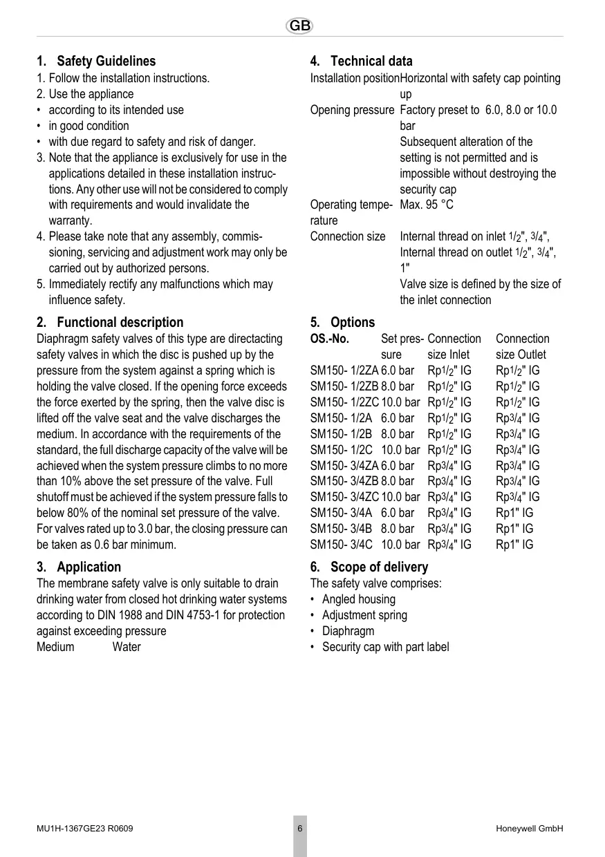
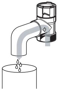
Risk of scaling through hot liquid escaping from the discharge opening.
Route discharge line so that neither personal injuries nor property damage can be caused by discharged fluid.

The discharge opening is marked by an arrow on the valve body
- Guide the outlet of the discharge line into a drain or container which can accept the total content of the system.


If there is a risk that the discharge line becomes clogged or can freeze, interrupt the discharge line, e.g. by a funnel. The discharge line of the funnel must have twice the cross-section of the safety valve intake
8. Commissioning
- Mount a warning sign readily visible near the discharge line or on the safety valve with the following text:

While heating, water must escape from the discharge line for safety reasons. Do not close!
- Make sure that all water connections are tight
- We recommend flushing the supply line before commissioning the plant
9. Maintenance
In accordance with DIN 1988, Part 8, the following operations should be carried out regularly. A planned maintenance scheme is recommended.
9.1 Inspection
To be carried out by an installation company or the operator.
Frequency: every 6 month
Risk of scaling through hot liquid escaping from the discharge opening.
Function check by verifying the response: While the system is operating, briefly open the safety valve by turning the cap. After closing the cap the valve must close again the backed up water drain completely.
9.2 Maintenance
To be carried out by an installation company Interval: once a year Risk of scaling through hot liquid escaping from the discharge opening.
If a malfunction is detected, a repair can be attempted by opening and closing the cap several times. A replacement is necessary if this action is not successful.
10. Disposal
- Brass housing
Spring steel adjustment spring
High grade synthetic material security cap - Hot water resistant elastomer diaphragm

Observe the local requirements regarding correct waste recycling/disposal!
SM150-3/4A 6,0 bar Rp3/4" IG Rp1" IG
SM150-3/4B 8,0 bar Rp3/4" IG Rp1" IG
SM150-3/4C 10,0 bar Rp3/4" IG Rp1" IG
6. Fornitura
MEm6paHHbI npEdoxpAHnTeHbI KJIanaH B COOTBeTCTBmC DIN 1988 n DIN 4753-1 nla 3aunTbI OT npEBblHeHnaBLeHn IpeHa3NaHeH NCKJIIOHTeJIbHO nIyBbINyCKaHnI INTbeBOI BObl I3 3aMKHyTbIX CnCTEm NITbeBOI TEPNoI BObl.
CpeHa BOda
- TexHnueckne XapaKTepeNCTnKn
TIOJIOXKeHHe Ha TOpN3OHTaNbHO
tpybo npoBoe peoOxpaHntbHbIM KOJIaKOM BBePx
IaBHeHne IpeDyuctaHObJeHoHa3aBOeHa Hauana 6,0,8,0 n1n 10,0 6ap
cpa6bTaBbAHn IocneIyUo7a peryInpOBKa yctaHOJIeHOrO Ha 3aBOJe DaJIeHnIcpa6BaTbIBAHn HEDOnyCTmHa n HeBO3MOxHa 6e3 pa3pyuHnI npedoxpAHNTelbHorO kONpaYka
Pabocay Max.95°C Tempepatya
Pa3mep BHytpenHnpe3b6a co cToPOhB
natpy6ka BXoJa 1/2",3/4",BHyTpENHn
pe3b6a co cToPOhBi BblXoJa 1/2",
3/4",1"
Pa3Mepom KlaapanaHa YBnIeTcpa3Mep npincoeHHeHna HbXoDe
5.Obbemnoctabkn
Nap. TaBHeH Pa3Mep Pa3Mep eHaJana npuCoEInHe npuCoEInHe cpa6aTbI HnHa BaXoDeJe Ha BbIXOe BAHN
SM150- 1/2ZA 6,0 6ap Rp1/2" B/pe3. Rp1/2" B/pe3.
SM150- 1/2ZB 8,0 6ap Rp1/2" B/pe3. Rp1/2" B/pe3.
SM150- 1/2ZC 10,06ap Rp1/2" b/pe3. Rp1/2" b/pe3.
SM150- 1/2A 6,0 6ap Rp1/2" B/pe3. Rp3/4" B/pe3.
SM150- 1/2B 8,06ap Rp1/2"B/pe3.Rp3/4"B/pe3.
SM150- 1/2C 10,0 6ap Rp1/2" B/pe3. Rp3/4" B/pe3.
SM150-3/4ZA 6,0 6ap Rp3/4" B/pe3. Rp3/4" B/pe3.
SM150-3/4ZB 8,06ap Rp3/4"B/pe3.Rp3/4"B/pe3.
SM150-3/4ZC 10,06apRp3/4"B/pe3.Rp3/4"B/pe3.
SM150-3/4A 6,0 6ap Rp3/4" B/pe3. Rp1" B/pe3.
SM150-3/4B 8,06ap Rp3/4" B/pe3.Rp1"B/pe3.
SM150-3/4C 10,06apRp3/4"Bpe3.Rp1"Bpe3.
6.ObbEmnoCTaBKn
PpeoXpaHnteJbHbI KJIanaH COCTOHT I3:
Kopnyc ByrIIOBOM mCOnJHHeHm
- PerynipyeMa npyknHa
- MemópaHa
- Празхантульный колачok схаразсерцкий DeТали
7. MoHTaX
7.1PykoBOdCTBO no yctaHOBKe
- MoHTIpOBaTb npEoXpaHnTeNbHbI KNaHaN npei HarpeBaTeJeM BOdb I TpybOpBoD XOJNoHOH BObl
OcuyeCTBnTb yctaHOBky TaK, YTO6bl: oMeJdy npedoxpaHHTeJIbHbIM KJIaHaOM n reHepaTOPom TEnla He 6bIIO 3aOpHoi apMaTpybl, cyjKeHNI uCIT oobecneuBaIacb xopoOee yDObCTBO DoCTyNa dIЯ npoBeDeHnpeMOHTbIX pa60t N pa60 T NO TexHnueckomy O6cnyJBaHHIO o npedoxpaHHTeJIbHbI KJIaHaPacNoIarIcN haRreHepaTOPom TEnla
OMeJy PpeOxpaHNTbHbIM KlaHaHOM I reHepaTopom 6blna yctaHOBHeHa npMaia coeINHTbHnA LInnA DInHO He 60Je e 1 M pa3Mepom BxODHOro nonepueHOrO ceeHnA
-П配电хангельньклалан Должени bbyyctaHOBJIEN TAK,чTO6bl BO BCTpoEHHOM COCTOHN Ha Hero He DeiCTBOBAJIN BHeUHnE CNJIbI
BbIyckHOI Tpy6oNpOBoODdoJIoJIeH 6bITb BblIOJIHEn no pa3Mepy BbIXoDHorO nonepueHOrO ceyehn IpeoXpaHHTenbHorO KlaanapaHa Hne doJIoJIeH Imetb 6oJee 2 KoJIeH, a TaKKe He doJIoJIeH 6bITdINHOH 6oJee 2 M
BbIyucKHO Tpy6oPBOoD dOJKeH 6bITb npoloxeH cHaKIOHOM
7.2 INHCTpykmaNo yctaHOBe
3anpeuaeTce nepereBaTb npdoxpanHTeNbH knaHnB pe3yIbTaTe npoBeHnra paobT no CBapKe nn naKe K yctaHOBe. YcTaHabNBAtB npdoxpanHTeNbH knaHnTObKO nocne npoBeHnra TAKO poJa paobT.
- TúaTeJIbHo CneIte BOyu n3 Tpy6oPBoOda
2.YctaHOBtB Mem6paHHbI npedoxpAHNTeJIbHbIKlanah OPi coeINHeHN 3aTgINBaTb PnCoeINHeHc MOMeHTOM MaKc.18 Hm. Ppi CnJIbHOM 3aTgINBaHIn B MaTePnaIe MOrYT 6pbazbIBaTbCra TpeuHbI, YTO MoKeT npNBecTN K yTeUkAM B yCTaHOBke.
O MoTaqB TROP30HTaJIbHbI Tpy6OpPBOoD npedoxpaHnTeJbHbIM KOLNaqKOM BBePx O O6paTte BHMaHne Ha HapBaJIeHne IOTOKa O UCTaHaBJIbAai Te 6e3 NepeKocOB n 13rIbAioUeHO HanpJKeHnI
- YctaHOBntb BblnyckHOn Tpy6OpBOD

OnachocTb noIyueHnOxorOBOT BbIXoJaSei, ropJeJ KUdkocTn Ha BblNyckHom OTBepCTNI. UloxNtB bblNyckHO Tpy6OpBOvD TaK, UTObblXbIXoJaA JIKIOcTb He CMOrIa npuHnHTb BpeI IHOJAM NII NceHHOMY IMyIeCTBy.

Bbinyckhoe OTBepCTne OTMeueHo CTpeIkoi Ha Kopnyce KlananaHa
- HanpaBntb BixOd nToKa BblnycHOro Tpy60npoBoJa B dpeHaXhBn CTOK INI NEMKOCtB, CnOcO6HyIO BmecTHTb BeCb O6bEm yctaHOBKn.

B clyuae Bo3HKnHOBeHnnaOaCHOCTn 3aKynopBaHnna Nnn 3aMep3aHnra BbIyNcKHoro Tpy6OpnoBOda Heo6XoDmIO OcyIeCTBnTb pa3beDInHeHne BbIyNcKHoro Tpy6OpnoBOda (HaPnimep, BOPoHko). Y BbIyNcKHoro Tpy6OpnoBOda BOPOHKn DoJxHo 6bItb DBoHoe NopepuHoe CeueHne BXOda npedoxpaHntelhoro Klanana
8. BbOД bKcPJIpyTaUIO
- Pa3MeCTnTb B6IIN3N BbIyNcKHO Tpy6oPBOOda INI Ha IpeOxpaHInTeJbHOM KJIaNaHe XOpSo WbIMMyTO TabIuKy C yka3aHHe m CneDyUoIeRO COdePkaHn:

Bo Bpemr OTOPnIeHn I3 COOpaXeHn 6e3oNaChocTn I3 BbInyCKHO TpyboNPOB0da DOnKHa BbIXoDntb BOa. He 3akynopuBaTb!
2.ПоверпьВОДОнгpoHицaEMOCТьСЕХпИСоЕДИНЕНИВОДЛ
3.Пелед ВВОДOMВЗКПУАТAUHUGYCTAHOBKNMbI peKOMeHdYeMпОмБИТь BOДОПРОВODYCETb
9. yxoJ
BcootBeCTBnC DIN1988, Yactb 8 Heo6xOIMO peryIaRHOe npOBeHne npNBeDeHHbIX daJeepoPnpTm. Mbl peKOMeHNyEm 3akNIOHTb DOROBOP TexHnueCKOrO o6cnyXnBaHnM MeJdy 3KcIIpyaTaUOnHHNKOM m PpeDnPrTNeM, OcyIeCTBnBWM yCTaHOBVk.
9.1Инспкция

Automation and Control Solutions
Honeywell GmbH
Hardhofweg
D-74821 Mosbach
Phone: (49) 6261 810
Fax: (49) 6261 81309
http://europe.hbc.honeywell.com
www.honeywell.com
Manufactured for and on behalf of the
Environmental and Combustion Controls Division of
16, Switzerland by its Authorised Representative Honeywell GmbH
MU1H-1367GE23 R0609
Subject to change
- F
- Functional description
- Application
- Technical data
- Options
- Scope of delivery
- Assembly
- Installations Guidelines
- Assembly instructions
- Commissioning
- Maintenance
- Inspection
- Maintenance
- Disposal
- Fornitura
- 6.ObbEmnoCTaBKn
- MoHTaX
- INHCTpykmaNo yctaHOBe
- BbOД bKcPJIpyTaUIO
- yxoJ
- 9.1Инспкция
- Automation and Control Solutions
Brand : HONEYWELL
Model : SM150
Category : Safety valve