
SG150D - Control valve HONEYWELL - Free user manual and instructions
Find the device manual for free SG150D HONEYWELL in PDF.
| Product type | Combined safety valve with pressure reducer |
| Brand | Honeywell |
| Model | SG150D |
| Fluid | Water |
| Max. upstream pressure | 16 bar |
| Adjustable downstream pressure | 1 - 10 bar (factory setting 6, 8 or 10 bar) |
| Max. operating temperature | 40 °C |
| Connection sizes | 1/2" and 3/4" |
| Mounting position | Horizontal or vertical |
| Delivery contents | Complete valve, monitoring sleeves, shut-off valves, pressure reducer, fine filter (0.16 mm), backflow preventer, valve replacement kit, insulating sleeve |
| Housing material | Dezincification-resistant brass |
| Seal material | NBR |
| Main functions | Pressure reduction, non-return valve, shut-off valve, membrane safety valve |
| Maintenance and cleaning | Cleaning the filter and sediment bowl; annual maintenance of the reducer and check valve; purging the safety valve every 6 months |
| Safety | Factory-set safety valve (6, 8 or 10 bar); not adjustable without destruction |
| Available spare parts | Valve replacement kit, replacement filter, O-rings, strainer bowl, double hex key ZR06K |
| Repairability | Possible replacement of valve seals, check valve and filter by a professional |
| Accessories | Pressure gauge M08M, fitting set VST06-A/B, pressure regulator D150/D160S |
| General information | 30-page instruction manual available in several languages; certified TRD 721 for pressure 1-10 bar |
Frequently Asked Questions - SG150D HONEYWELL
User questions about SG150D HONEYWELL
0 question about this device. Answer the ones you know or ask your own.
Ask a new question about this device
Download the instructions for your Control valve in PDF format for free! Find your manual SG150D - HONEYWELL and take your electronic device back in hand. On this page are published all the documents necessary for the use of your device. SG150D by HONEYWELL.
USER MANUAL SG150D HONEYWELL
Keep instructions for later use!
TUV·SV··-700-1/2"+3/4"W·p
6 bar 1/2" A152-1/2AA
3/4" A152-3/4AA
8 bar 1/2" A152-1/2AB
3/4" A152-3/4AB
10 bar 1/2" A152-1/2AC
3/4" A152-3/4AC
8 Ersatzsbie 1/2" + 3/4" ES06F-1/2A
9 O-Ring Satz 1 / 2^ + 3 / 4^ 0901246
(10 Stuck)
10 Klarsichtsbiebasse 1 / 2'' + 3 / 4'' SK06TG-1/2
13. Zubehör

fur SG150
M08M
D150/D160S
VST06-A

VST06-B
M08M Manometer
- Follow the installation instructions.
- Use the appliance
according to its intended use - in good condition
with due regard to safety and risk of danger. - Note that the appliance is exclusively for use in the applications detailed in these installation instructions. Any other use will not be considered to comply with requirements and would invalidate the warranty.
- Please take note that any assembly, commissioning, servicing and adjustment work may only be carried out by authorized persons.
- Immediately rectify any malfunctions which may influence safety.
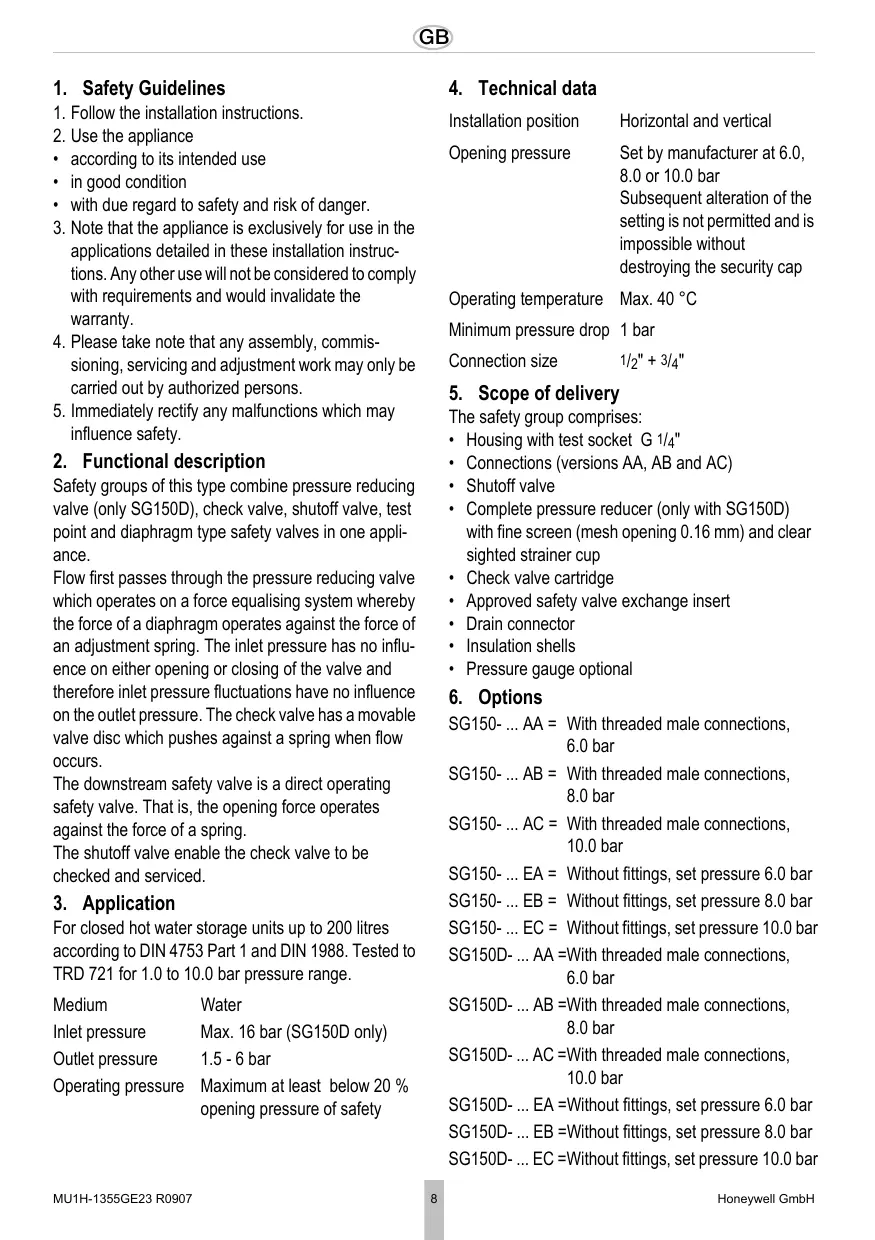
2. Functional description
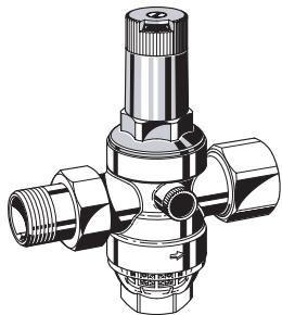
Safety groups of this type combine pressure reducing valve (only SG150D), check valve, shutoff valve, test point and diaphragm type safety valves in one appliance.
Flow first passes through the pressure reducing valve which operates on a force equalising system whereby the force of a diaphragm operates against the force of an adjustment spring. The inlet pressure has no influence on either opening or closing of the valve and therefore inlet pressure fluctuations have no influence on the outlet pressure. The check valve has a movable valve disc which pushes against a spring when flow occurs.
The downstream safety valve is a direct operating safety valve. That is, the opening force operates against the force of a spring.
The shutoff valve enable the check valve to be checked and serviced.
3. Application
For closed hot water storage units up to 200 litres according to DIN 4753 Part 1 and DIN 1988. Tested to TRD 721 for 1.0 to 10.0 bar pressure range.
Medium Water
Inlet pressure Max. 16 bar (SG150D only)
Outlet pressure 1.5 - 6 bar
Operating pressure Maximum at least below 20% opening pressure of safety
4. Technical data
Installation position
Horizontal and vertical
Opening pressure
Set by manufacturer at 6.0, 8.0 or 10.0 bar
Subsequent alteration of the setting is not permitted and is impossible without destroying the security cap
Operating temperature
Max. 40^
Minimum pressure drop
1 bar
Connection size
1/2" + 3/4"
5. Scope of delivery
The safety group comprises:
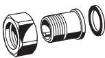
Housing with test socket G 1/4"
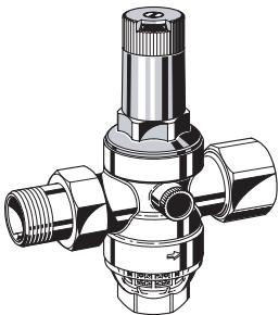
- Connections (versions AA, AB and AC)
- Shutoff valve
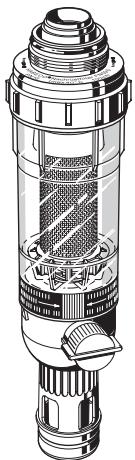
- Complete pressure reducer (only with SG150D) with fine screen (mesh opening 0.16mm ) and clear sighted strainer cup
- Check valve cartridge
Approved safety valve exchange insert
- Drain connector
Insulation shells
Pressure gauge optional
6. Options
SG150- ... AA = With threaded male connections, 6.0 bar
SG150-...AB = With threaded male connections, 8.0 bar
SG150- ... AC = With threaded male connections, 10.0 bar
SG150- ... EA = Without fittings, set pressure 6.0 bar
SG150-...EB = Without fittings, set pressure 8.0 bar
SG150- ...EC = Without fittings, set pressure 10.0 bar
SG150D- ... AA =With threaded male connections, 6.0 bar
SG150D- ... AB =With threaded male connections, 8.0 bar
SG150D- ... AC =With threaded male connections, 10.0 bar
SG150D-...EA = Without fittings, set pressure 6.0 bar
SG150D-...EB = Without fittings, set pressure 8.0 bar
SG150D-...EC=Without fittings, set pressure 10.0 bar
7. Assembly
7.1 Installations Guidelines
- Safety group must be fitted in the cold water supply to the hot water storage unit
- Installation in horizontal or vertical pipeline possible
- The installation must be carried out so that:
o There are no shutoff valves or fittings, narrowing of the pipework or strainers between the water heater and the safety valve
o Good access is provided for service and maintenance
o The safety valve is fitted above the top of the water heater to avoid the need for draining down when exchanging the safety valve insert
- If there is no drainage facility in the room where the heater is installed, then the safety valve may be fitted in an adjacent area. DIN 1988, part 2 is to be observed
- Distance to the water heater approx. 1m
- While heating, water must escape in the discharge line for safety reasons. Do not close off!
- The drain line of the membrane safety valve must be viewable!
- If the drain guide is not connected directly with the safety group, a discharge line must be installed between the safety group and the drain guide!
- The discharge line must be performed to the size of the safety valve discharge cross-section and may not have more than 2 elbows and or be longer than 2m !
- If, for compelling reasons, more elbows or a greater length becomes necessary, then the entire discharge line must be designed to a larger nominal width. More than 3 elbows, as well as lengths over 4m are not permitted!
- The discharge line must be installed with an incline!
7.2 Assembly instructions
- Blow out or rinse pipe line out well
- Install safety group in the cold water line o Note flow direction o Install without tension or bending stresses
8. Commissioning
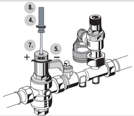
8.1 Setting outlet pressure

Set outlet pressure min. 1 bar under inlet pressure.
- Close shutoff valve on inlet
- Release pressure on outlet side (e.g. through water tap)
- Close shutoff valve on outlet
- Loosen slotted screw o Do not remove slotted screw
- Slacken tension in compression spring o Turn control handle to the left (-) until it does not move any more
- Slowly open shutoff valve on inlet
- Turn control handle until the setting scale shows the desired value
- Retighten slotted screw
- Slowly open shutoff valve on outlet
9. Maintenance

DIN 1988, Part 8 specifies that the following operations be carried out regularly.
A scheduled maintenance scheme is recommended.
9.1 Inspection
9.1.1 Pressure reducing valve

Interval: once a year
- Close shut off valve on outlet
- Check back pressure using a pressure meter when there is zero through-flow
o If the pressure is increasing slowly, the valve may be dirty or defective. In this instance, carry out servicing and cleaning
- Slowly open shutoff valve on outlet
9.1.2 Check valve

Interval: once a year
- Close shut off valve on outlet
- Open check valve o Until the pressure is released, some water will flow out of the check valve. After a short period of time the water flow should stop. If the water continues to drip or run, then the backflow preventer must be replaced - see servicing of backflow preventer
- Close check valve again
- Open shut-off valve again
9.1.3 Safety valve

Frequency: every 6 month
- Actuate lifting device
- Release lifting device
- Shut-off valve closes
-
available water flows completely off Malfunction:
-
Actuate lifting device multiple times, if necessary initiate repairs
9.2 Maintenance
9.2.1 Pressure reducing valve

Frequency: every 1-3 years (depending on local operating conditions)
To be carried out by an installation company
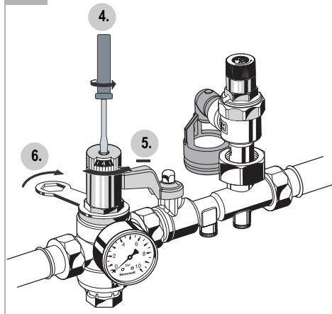
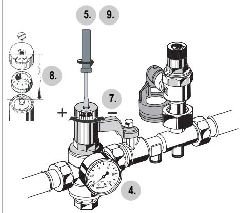
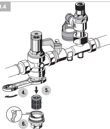
- Close shutoff valve on inlet
- Release pressure on outlet side (e.g. through water tap)
- Close shutoff valve on outlet
- Loosen slotted screw o Do not remove slotted screw

There is a spring in the spring bonnet. It may cause injuries if the spring is derailing.
-
Make sure tension in compression spring is slakkened!
-
Slacken tension in compression spring o Turn control handle to the left (-) until it does not move any more
-
Unscrew spring bonnet o Use double ring wrench ZR06K
-
Remove slip ring
-
Remove valve insert with a pair of pliers
-
Unscrew filter bowl o Use double ring wrench ZR06K
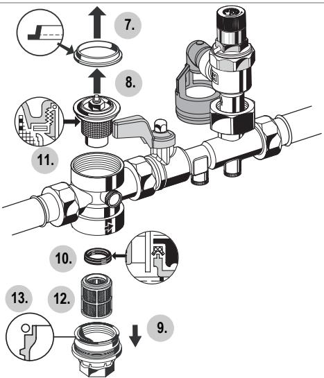
10.Remove slotted ring
- Check that sealing ring, edge of nozzle and slotted ring are in good condition, and if necessary replace the entire valve insert
12.Remove filter, clean and reinsert - Place O-ring onto filter bowl
14.Reassemble in reverse order

Press in diaphragm with finger before inserting slip ring
Screw in filter cup hand-tight (without tools)
- Adjust setting scale and set outlet pressure
9.2.2 Check valve

To be carried out by an installation company
- Close shutoff valve on inlet
- Release pressure on outlet side (e.g. through water tap)
- Close shutoff valve on outlet
- Replace check valve
9.3 Adjusting the setting scale
If the adjustment knob is removed, this setting is lost. A new setting can be achieved using a pressure gauge.
- Close shutoff valve on inlet
- Release pressure on outlet side (e.g. through water tap)
- Close shutoff valve on outlet
- Fit manometer
- Loosen slotted screw o Do not remove slotted screw
- Slowly open shutoff valve on inlet
- Set desired outlet pressure (e.g. 4 bar)
- Align scale (e.g. 4) in middle of viewing window
- Retighten slotted screw
- Slowly open shutoff valve on outlet
9.4 Cleaning

Caution!
Do not use any cleaning agents containing solvents and/or alcohol to clean the plastic parts!
If necessary, the filter bowl and the filter can be cleaned.

To be carried out by an installation company or the operator.

Detergents must not be allowed to enter the environment or the sewerage system!
- Close shutoff valve on inlet
- Release pressure on outlet side (e.g. through water tap)
- Close shutoff valve on outlet
- Unscrew filter bowl o Use double ring wrench ZR06K
- Remove filter, clean and reinsert
- Place O-ring onto filter bowl
- Screw in filter cup hand-tight (without tools)
- Slowly open shutoff valve on inlet
- Slowly open shutoff valve on outlet
10. Disposal
- Dezincification resistant brass housing
- Brass threaded connections
- Stainless steel filter mesh on pressure reducing valve
- Transparent synthetic material filter bowl on pressure reducing valve
- High grade synthetic material pressure reducing valve insert, spring bonnet with adjuster knob,
shutoff valves, test socket, check valve, safety valve insert and drain connector
- Fibre-reinforced NBR diaphragm
NBR seals
EPP insulation shells

Observe the local requirements regarding correct waste recycling/disposal!
- Troubleshooting
| Problem | Cause | Remedy |
| SG150 and SG150D | ||
| Drips | During the heating up of the water heater | no error, normal function |
| Continually drips from soiling | Actuate lifting grip multiple times so that dirt particles are flushed out, or replace as necessary | |
| Backflow stopper does not close off tightly in the front pressure area. | Pressure increase in the front pres-sure area | Replace backflow stopper |
| Seal surfaces dirty or worn | Replace backflow stopper | |
| Too little or no water pressure | Cut-off fixtures before or after the safety group not opened entirely | Open the shutoff valves fully |
| Safety group not installed in the flow direction | Install safety group in flow direction (observe arrow direction on housing) | |
| only SG150D | ||
| Water is escaping from the spring bonnet | Diaphragm in valve insert is faulty | Replace valve insert |
| Too little or no water pressure | Pressure reducing valve is not set to the desired outlet pressure | Set outlet pressure |
| Filter in pressure reducing valve is contaminated | Clean or replace filter | |
| The outlet pressure set does not remain constant | Filter in pressure reducing valve is contaminated or worn | Clean or replace filter |
| Valve insert, sealing ring or edge of nozzle is contaminated or worn | Replace valve insert | |
| Rising pressure on outlet (e.g. in boiler) | Check check valve, safety group etc. | |
| Expansion water from the hot water purifier | Inspect backflow stopper before the hot water purifier and single-lever mixing valve if necessary. | |
| Close shut-off valves to the hot water puri-fier supply line. Open hot water tap connec-tion. Does pressure remain constant? Expansion water of the hot water purifier. Does pressure increase? Pressure reducer defect. | ||
12. Spare Parts
No.Description Dimension Part No.
1 Safety valve exchange insert
$$ \begin{array}{l} \text {A p p r o v a l N o .} - \mathrm {T U V} \cdot \mathrm {S V} \dots^ {} - 6 1 7 - 1 / 2 ^ {\prime \prime} + 3 / 4 ^ {\prime \prime} \cdot W \cdot p \ \text {A p p r o v a l N o .} - \mathrm {T U V} \cdot \mathrm {S V} \dots^ {} - 7 0 0 - 1 / 2 ^ {\prime \prime} + 3 / 4 ^ {\prime \prime} \cdot W \cdot p \ \end{array} $$
$$ \begin{array}{l} 6 \text {b a r} \quad 1 / 2" \quad A 1 5 2 - 1 / 2 A A \ 3 / 4 ^ {\prime \prime} \quad A 1 5 2 - 3 / 4 A A \ 8 \text {b a r} \quad 1 / 2" \quad A 1 5 2 - 1 / 2 A B \ 3 / 4 ^ {\prime \prime} \quad A 1 5 2 - 3 / 4 A B \ 1 0 \text {b a r} \quad 1 / 2" \quad A 1 5 2 - 1 / 2 A C \ 3 / 4 ^ {\prime \prime} \quad A 1 5 2 - 3 / 4 A C \ \end{array} $$
..* valid approval No.
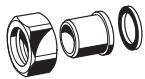
2 Blanking plug with O-ring R1/4" (5 pcs.) S06K-1/4
3 Discharge tundish TA160S
4 Check valve insert 1 / 2^ 2166200 3 / 4^ 2110200
5 Sealing ring 1/2" 0901443 (10 pcs.) 3/4" 0901444
6 Spring bonnet 1 / 2^ + 3 / 4^ 0901515 complete with setting scale
7 Valve insert 1 / 2^ + 3 / 4^ D06FA-1/2 complete (without filter)
8 Replacement filter 1 / 2'' + 3 / 4'' ES06F-1/2A
9 O-ring (10 pcs.) 12'' + 34'' 0901246
10 Filter bowl 1 / 2^ + 3 / 4^ SK06TG-1/2
13. Accessories
für SG150
M08M
D150/D160S

VST06-A
VST06-B
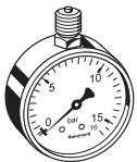
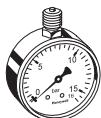
M08M Pressure gauge
Housing 50mm , connecting pin above G1/4"
Partition: 0-16 bar
D150 Pressure reducing valve
Pressure reducer D150-1/2 for completion of the safety group SG 150 with connection size 1 / 2
D160S Pressure reducing valve
Pressure reducer D160S-3/4 for completion of the safety group SG 150 with connection size 3 / 4^
VST06-A Connection set
Threaded connections
VST06-B Connection set
Solder connections
für SG150D
FN09S

M07M
M08M
ZR06K

VST06-A


VST06-B
FN09S HABEDO® Retrofit filter
Reverse-rinsing filter for retro-conversion to a filter combination unit of pressure reducing valves
M07M Pressure gauge
Housing diameter 63mm ,rear connection thread
G1/4". Ranges: 0 - 4, 0 - 10, 0 - 16 or 0 - 25 bar. Please indicate upper value of pressure range when ordering
M08M Pressure gauge
Housing 50mm , connecting pin above G1/4"
Partition: 0-16 bar
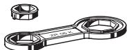
ZR06K Double ring wrench
For removal of spring bonnet and filter bowl
VST06-A Connection set
Threaded connections
VST06-B Connection set
Solder connections
6 bar 1/2" A152-1/2AA
3/4" A152-3/4AA
8 bar 1/2" A152-1/2AB
3/4" A152-3/4AB
10 bar 1/2" A152-1/2AC
3/4" A152-3/4AC
TUV·SV··* - 617 - 1/2" + 3/4" ·W·p
TUV·SV··* - 700 - 1/2" + 3/4" ·W·p
6 bar 1/2" A152-1/2AA
3/4" A152-3/4AA
8 bar 1/2" A152-1/2AB
3/4" A152-3/4AB
10 bar 1/2" A152-1/2AC
3/4" A152-3/4AC
Automation and Control Solutions
Honeywell GmbH
Hardhofweg
D-74821 Mosbach
Phone: (49) 6261 810
Fax: (49) 6261 81309
http://europe.hbc.honeywell.com
www.honeywell.com
Manufactured for and on behalf of the
Environmental and Combustion Controls Division of
Honeywell Technologies Sàrl, Ecublens, Route du
Bois 37, Switzerland by its Authorised Representative Honeywell GmbH
MU1H-1355GE23 R0907
Subject to change
© 2007 Honeywell GmbH
Honeywell
8.1
9.2.1
9.3
9.4
D
- Safety Guidelines.. 8
- Functional description 8
- Application 8
- Technical data 8
- Scope of delivery 8
- Options 8
- Assembly 9
- Commissioning 9
- Maintenance 9
- Disposal 10
- Troubleshooting 11
- Spare Parts 12
- Accessories 13