
SM110 - Smoke detector HONEYWELL - Free user manual and instructions
Find the device manual for free SM110 HONEYWELL in PDF.
| Product Type | Diaphragm Safety Valve |
| Brand | Honeywell |
| Model | SM110 |
| Category | Smoke Detector (as per label, but actually safety valve) |
| Opening Pressure (preset) | 1.5, 2.0, 2.5, 3.0, 4.0, or 6.0 bar |
| Connection Size - Inlet | Rp1/2" or Rp3/4" internal or external thread |
| Connection Size - Outlet | Rp1/2", Rp3/4", or Rp1" internal thread |
| Operating Temperature | Max. 120°C |
| Installation Position | Horizontal with safety cap pointing up |
| Flow Direction | Marked by arrow on valve body |
| Materials - Housing | Brass |
| Materials - Spring | Spring steel |
| Materials - Cap | High grade synthetic material |
| Materials - Diaphragm | Hot water resistant elastomer |
| Max. Tightening Torque | 18 Nm |
| Max. Pipe Length to Heat Exchanger | 1 m (straight, full diameter) |
| Discharge Line Max. Length | 2 m with max. 2 elbows |
| Inspection Interval | Every 6 months |
| Maintenance Interval | Annually |
| Set Pressure Alteration | Not permitted, impossible without destroying cap |
| Scope of Delivery | Angled housing, adjustment spring, diaphragm, security cap with label |
| Disposal Notes | Separate materials: brass housing, spring steel, synthetic cap, elastomer diaphragm; follow local regulations |
Frequently Asked Questions - SM110 HONEYWELL
User questions about SM110 HONEYWELL
0 question about this device. Answer the ones you know or ask your own.
Ask a new question about this device
Download the instructions for your Smoke detector in PDF format for free! Find your manual SM110 - HONEYWELL and take your electronic device back in hand. On this page are published all the documents necessary for the use of your device. SM110 by HONEYWELL.
USER MANUAL SM110 HONEYWELL
Keep instructions for later use!
Diaphragm safety valve
- Safety Guidelines 6
- Functional description 6
- Application 6
- Technical data 6
- Options 6
- Scope of delivery 6
- Assembly 7
- Commissioning 7
- Maintenance 8
- Disposal 8
F
- Follow the installation instructions.
- Use the appliance
according to its intended use
- in good condition
with due regard to safety and risk of danger.
3. Note that the appliance is exclusively for use in the applications detailed in these installation instructions. Any other use will not be considered to comply with requirements and would invalidate the warranty.
4. Please take note that any assembly, commissioning, servicing and adjustment work may only be carried out by authorized persons.
5. Immediately rectify any malfunctions which may influence safety.
2. Functional description
Diaphragm safety valves of this type are directacting safety valves in which the disc is pushed up by the pressure from the system against a spring which is holding the valve closed. If the opening force exceeds the force exerted by the spring, then the valve disc is lifted off the valve seat and the valve discharges the medium. In accordance with the requirements of the standard, the full discharge capacity of the valve will be achieved when the system pressure climbs to no more than 10% above the set pressure of the valve. Full shutoff must be achieved if the system pressure falls to below 80% of the nominal set pressure of the valve. For valves rated up to 3.0 bar, the closing pressure can be taken as 0.6 bar minimum.
3. Application
The membrane safety valve is only suitable to drain the following media from closed heating systems according to EN 12828 for protection against exceeding pressure
Medium Water or glycol-water mixture, according to VDI 2035
Liquids of the fluid group 1 and 2 (pressure device guideline, item 9) which do not affect the materials used.
4. Technical data
Installation position Horizontal with safety cap pointing up
Opening pressure Factory preset to 1.5, 2.0, 2.5, 3.0, 4.0 or 6.0 bar Subsequent alteration of the setting is not permitted and is impossible without destroying the security cap
Operating tempera-Max. 120^ ture
Connection size Internal thread on inlet 1 / 2^ 3 / 4^ Internal thread on outlet 1 / 2^ 3 / 4^ 1^ External thread on inlet 1 / 2^ with internal thread on outlet 3 / 4^ Valve size is defined by the size of the inlet connection
5. Options
| OS.-No. | Set pres- sure | Connection size Inlet | Connection size Outlet |
| SM110- 1/2ZA2.5 | 2.5 bar | Rp1/2" IG | Rp1/2" IG |
| SM110- 1/2ZA3.0 | 3 bar | Rp1/2" IG | Rp1/2" IG |
| SM110- 1/2A1.5 | 1.5 bar | Rp1/2" IG | Rp3/4" IG |
| SM110- 1/2A2.0 | 2.0 bar | Rp1/2" IG | Rp3/4" IG |
| SM110- 1/2A2.5 | 2.5 bar | Rp1/2" IG | Rp3/4" IG |
| SM110- 1/2A3.0 | 3.0 bar | Rp1/2" IG | Rp3/4" IG |
| SM110- 1/2A4.0 | 4.0 bar | Rp1/2" IG | Rp3/4" IG |
| SM110- 1/2A6.0 | 6.0 bar | Rp1/2" IG | Rp3/4" IG |
| SM110- 3/4ZA2.5 | 2.5 bar | Rp3/4" IG | Rp3/4" IG |
| SM110- 3/4ZA3.0 | 3.0 bar | Rp3/4" IG | Rp3/4" IG |
| SM110- 3/4A1.5 | 1.5 bar | Rp3/4" IG | Rp1" IG |
| SM110- 3/4A2.5 | 2.5 bar | Rp3/4" IG | Rp1" IG |
| SM110- 3/4A3.0 | 3.0 bar | Rp3/4" IG | Rp1" IG |
| SM110- 3/4A4.0 | 4.0 bar | Rp3/4" IG | Rp1" IG |
| SM110- 1/2AA1.5 | 1.5 bar | Rp1/2" AG | Rp3/4" IG |
| SM110- 1/2AA2.0 | 2.0 bar | Rp1/2" AG | Rp3/4" IG |
| SM110- 1/2AA3.0 | 3.0 bar | Rp1/2" AG | Rp3/4" IG |
6. Scope of delivery
The safety valve comprises:
Angled housing
- Adjustment spring
- Diaphragm
- Security cap with part label
7. Assembly
7.1 Installations Guidelines
- Mount the safety valve at the highest point of the heat generator or in its immediate vicinity on the flow line
- The installation must be carried out so that:
o no shut-off fittings, restrictions or strainers arelocated between safety valve and heat generator
o good access is provided for service and maintenance
o that the safety valve is positioned above the heat generator
o that between the safety valve and heat exchanger a max. 1 m long straight connection line with the size of the inlet diameter is installed
- The safety valve must be mounted so that in its installed condition no external forces act on it
- The discharge line must be performed to the size of the safety valve outlet diameter and may not have more than 2 elbows and or be longer than 2m
- The discharge line must be installed with an incline
7.2 Assembly instructions

The safety valve may not be overheated through welding and soldering work on the system. Install the safety valve only after these tasks are completed.
- Thoroughly flush pipework
- Install the membrane safety valve
o Tighten the connections with max. 18 Nm when joining. Cracks may form in the material when tighten to strongly which may cause leaks in the system.
o Installation in horizontal pipe with safety cap pointing up
o Note flow direction
o Install without tension or bending stresses
- Install discharge line

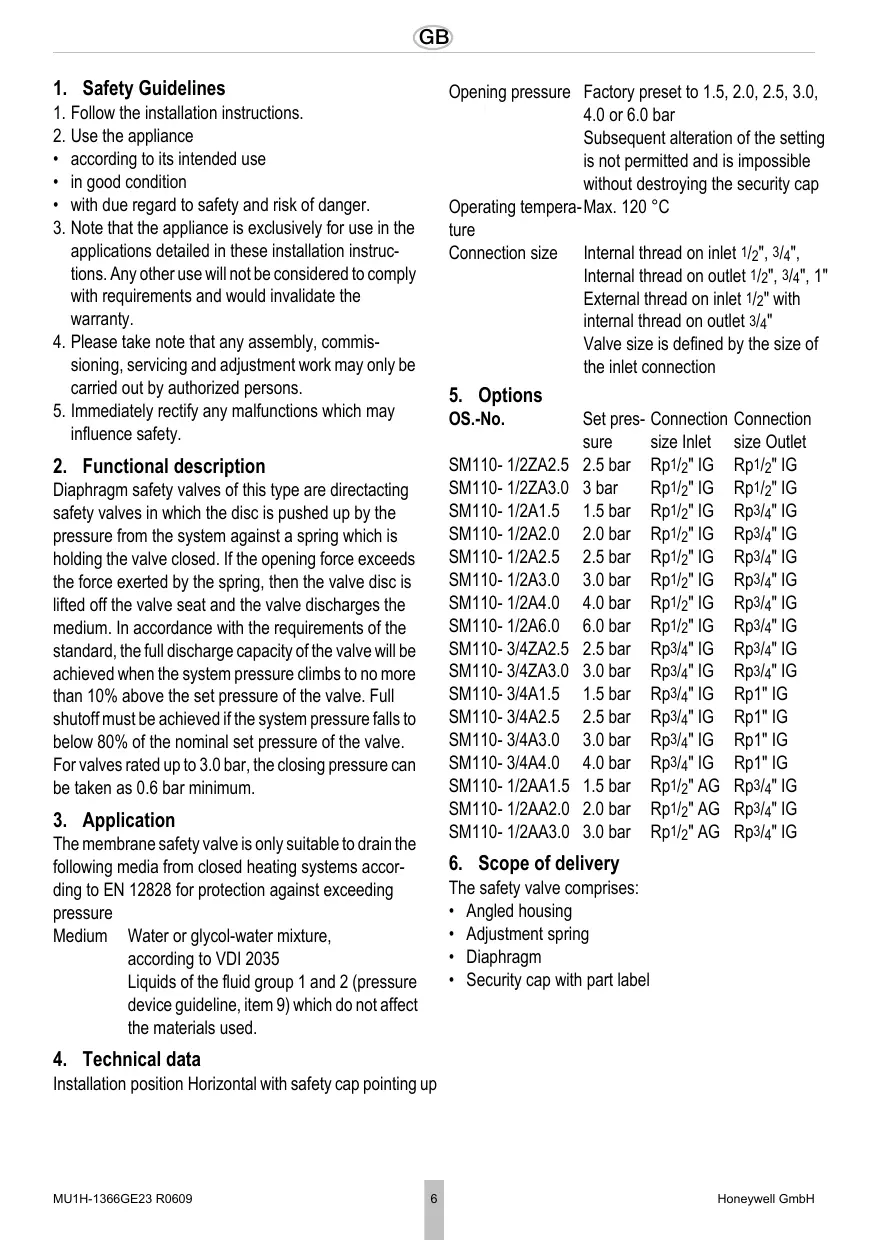
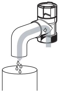
Risk of scaling through hot liquid escaping from the discharge opening.
Route discharge line so that neither personal injuries nor property damage can be caused by discharged fluid.

The discharge opening is marked by an arrow on the valve body
- Guide the outlet of the discharge line into a drain or container which can accept the total content of the system.

If there is a risk that the discharge line becomes clogged or can freeze, interrupt the discharge line, e.g. by a funnel. The discharge line of the funnel must have twice the cross-section of the safety valve intake
8. Commissioning
- Mount a warning sign readily visible near the discharge line or on the safety valve with the following text:

While heating, water must escape from the discharge line for safety reasons. Do not close!
- Make sure that all water connections are tight
- We recommend flushing the supply line before commissioning the plant
9. Maintenance
In accordance with DIN 1988, Part 8, the following operations should be carried out regularly. A planned maintenance scheme is recommended.
9.1 Inspection
To be carried out by an installation company or the operator.
Frequency: every 6 month
Risk of scaling through hot liquid escaping from the discharge opening.
Function check by verifying the response: While the system is operating, briefly open the safety valve by turning the cap. After closing the cap the valve must close again the backed up water drain completely.
9.2 Maintenance
To be carried out by an installation company Interval: once a year Risk of scaling through hot liquid escaping from the discharge opening.
If a malfunction is detected, a repair can be attempted by opening and closing the cap several times. A replacement is necessary if this action is not successful.
10. Disposal
- Brass housing
Spring steel adjustment spring
High grade synthetic material security cap - Hot water resistant elastomer diaphragm
Observe the local requirements regarding correct waste recycling/disposal!
7.1 Montage-instructions
ONaCHocTbNoJUyehnOxOroB OTo BbIXoJaIe, TropJeH KUnDKoCTn Ha BbIpyCKHOM OTBepCTnN.
B cnyae HapyueneH yHKUHOHPOBAHn MOxHo nonbTaTcR npOn3Becr peMOHT nyTEM MHOROKpaTHoro OTKpbIBaHn N 3aKpbIBaHn KONpauka. Ecnn JKe 3TO He NOMOrI, To Heo6XoDMO ocuueCTBnTb 3aMeHy.
10.YtJIn3aun
Kopnyc n3 naTyHn
- HactpoeHna npyXnHa n3 npyXHHo CTaH
- Празханпеловский Кларан ИЗ ВсICOKOKaЧECTВЕнHOД ПЛаCTMACCbI
- Mem6paHa n3 yctOuYbIX K rOpAeB BoJe 3naCTOMepOB
Co6JIIOdaTb MeCTHbIe Tpe6ObaHnI NO yTNIN3aCmN INy yHNHTOKeHNIO OTXoD0B
Automation and Control Solutions
Honeywell GmbH
Hardhofweg
D-74821 Mosbach
Phone: (49) 6261 810
Fax: (49) 6261 81309
http://europe.hbc.honeywell.com
www.honeywell.com
Manufactured for and on behalf of the
Environmental and Combustion Controls Division of
16, Switzerland by its Authorised Representative Honeywell GmbH
MU1H-1366GE23 R0609
Subject to change
Brand : HONEYWELL
Model : SM110
Category : Smoke detector