
HF 49 - Descaler HONEYWELL - Free user manual and instructions
Find the device manual for free HF 49 HONEYWELL in PDF.
| Product type | Dirt separator and deaerator for heating circuit |
| Brand | HONEYWELL |
| Model | HF 49 |
| Connection | DN25 (nominal diameter) |
| Nominal pressure / max. working | PN10 bar / 10 bar |
| Nominal flow | 3.6 m³/h |
| Pressure loss (at nominal flow) | 0.2 bar |
| Kvs value | 7.8 m³/h |
| Max. operating temperature | 90°C |
| Materials | Dezincification-resistant brass body, EPDM gaskets, PE insulating foam |
| Separation principle | Cyclonic for sludge, rapid deaeration with float, integrated magnet for ferrous particles |
| Anti-corrosion option | Phosphate cartridge (do not use if aluminum is present in the circuit) |
| Delivery contents | Body, connection with screwable ends and gaskets, rapid deaerator, magnet plug, insulating shell, ball valve |
| Variants | HF49-1A (standard model) |
| Routine maintenance | Periodic flushing via drain valve (4 to 6 L), cleaning rapid deaerator, cleaning magnet |
| Annual maintenance | Replacement of phosphate cartridge (if installed) |
| Spare parts | Deaerator EE49, ball valve KH49 |
| Safety | Use according to specifications, installation by professional, frost protection and protection against pollutants |
| Accessories | Phosphate cartridge for anti-corrosion protection |
Frequently Asked Questions - HF 49 HONEYWELL
User questions about HF 49 HONEYWELL
0 question about this device. Answer the ones you know or ask your own.
Ask a new question about this device
Download the instructions for your Descaler in PDF format for free! Find your manual HF 49 - HONEYWELL and take your electronic device back in hand. On this page are published all the documents necessary for the use of your device. HF 49 by HONEYWELL.
USER MANUAL HF 49 HONEYWELL
Keep instructions for later use!
Sludge and Air Separator
- Safety Guidelines 7
- Functional description 7
3.Application. 7 - Technical data 7
- Scope of delivery 7
- Options 7
- Assembly 7
- Commissioning 8
- Inspection 8
10.Maintenance 8
11.Disposal 9
12.Spare Parts 10 - Accessories 10
F
- Follow the installation instructions.
- Use the appliance
according to its intended use - in good condition
with due regard to safety and risk of danger. - Note that the appliance is exclusively for use in the applications detailed in these installation instructions. Any other use will not be considered to comply with requirements and would invalidate the warranty.
- Please take note that any assembly, commissioning, servicing and adjustment work may only be carried out by authorized persons.
- Immediately rectify any malfunctions which may influence safety.
- Arbitrary changes are not permitted for safety reasons. Original parts and accessories have been designed especially for this device and can be acquired from sanitation wholesalers.
- The manufacturer is in no way liable for damages that result from modifying the sludge and air separator or usage of not original parts.
2. Functional description
The sludge and air separator serves to separate sludge and air from the heater system.
It is equipped with a sludge and contamination reduction that functions according to the cyclone principle. This guarantees an effective separation of the particles.
The sludge and air separator is equipped with a quick bleeder for the air separation. If there is air in the system, it will rise to the highest point of the sludge and air separator. The water level drops there, the integrated floater pulls the floater arm down and thereby opens the sealed area. The air bleeds out whereby the water level rises again and the sealed area is closed again.
The optionally available phosphate cartridge counters the corrosion in the heater system. This dosing serves as an additional protection of the heater system; not as a replacement of the basic conditioning of the heater water by inhibitors.
3. Application
The sludge and air separator is installed in the heating circuit (feed and return line) and serves to separate sludge and air from the heater water.
4. Technical data
| Connection diameter | DN25 |
| Nominal pressure (PN) | 10 bar |
| Operating pressure | max. 10 bar |
| Nominal flow | 3,6 m³/h |
| Pressure loss during nominal flow rate | 0,2 bar |
| kVS-value | 7,8 m³/h |
| Operating temperature | max. 90°C |
5. Scope of delivery
The sludge and air separator consists of:
Housing
- Connection piece incl. couplings and seals
- Quick bleeder
- Blind plug including magnetic separator
Foam insulation jacket
Ball valve
6. Options
HF49-1A= Standard version
7. Assembly
7.1 Installations Guidelines
- The sludge and air separator is not suited for: o the separation of oils greases, solvents, soaps and other lubricating media o the separation of water-solvent materials
- The sludge and air separator is installed in the heating circuit (feed and return line)
- The heating system needs to be rinsed and filled
- The national installation regulations, general guidelines and technical data must be observed during the assembly
- The installation site has to be frost-free and the protection of the device from chemicals, paints, solvents, vapours and environmental influences must be guaranteed
- A course dirt separator needs to be installed up front for water with course dirt particles
- To ensure the bleeding of the air, the sludge and air separator has to be installed with the quick bleeder upwards
- The separator has to stand vertically; the connection piece can be built into horizontal and vertical lines
- Make sure the seals fit properly. The pressuresealing tightening of the screws has to be done cross-wise
Install stop valves ahead and following the sludge
and air separator
o This makes it possible to maintain the sludge and air separator easily without draining the heating system
- Mount the sludge and air separator at easily accessible points in the system

Before starting up, make sure that the ball valve of the device is closed.
7.2 Installation notes for the quick bleeder
- To prevent malfunctions of the quick bleeder by dirt particles that enter from the outside, the red valve cap should remain on the quick bleeder
- Leave the red valve cap open to just one rotation to the stop so that the air can bleed
o Thereby the quick bleeder will definitely not drip; dirt and floating particles cannot get into the bleeding mechanism
7.3 Installation into pipeline

Before installing the sludge and air separator, the pipelines need to be rinsed.
- Unpack the device and inspect for completeness and any possible transport damages
- Remove the insulation by loosening the securing clamps
- Thoroughly flush pipework
- Install rotatable connector piece o Note flow direction o Install without tension or bending stresses
- Before starting up, make sure that the ball valve is closed
7.4 Installing the phosphate cartridge (available as an accessory)

In case aluminium materials are used in the heater system, the phosphate cartridge may not be installed.
- Screw out the blind plug (SW27)
- Screw the phosphate cartridge into the sludge and air separator in clockwise direction
o The phosphate cartridge consists of a brass coupler, a magnet, a filter basket and the phosphate filling
- Screw the blind plug in with not too much force

If the phosphate cartridge should not be installed until after the startup, then proceed as described in chapter 10.3 Replace phosphate cartridge.
8. Commissioning

Before starting up, make sure that the ball valve is closed.
- Increase the water pressure slowly to the operating pressure of the heater (max. 10 bar)
- Slowly open the stop valve ahead of the sludge and air separator
- Visually check the sludge and air separator if it leaks
- Release the pressure in the sludge and air separator by opening the lower ball valve
- Close the lower ball valve again
- Slowly open the stop valve following the sludge and air separator
- Mount the insulation
9. Inspection
The following inspections need to be made regularly by the operator to ensure the proper functioning of the device.
- Leak checks, visual inspections
- Check for soiling every month
- Check the quick bleeder every year

The control intervals are the minimum recommendation and ought to be appropriately shortened by the operator if the consumer system is sensitive.
10. Maintenance

- Maintenance, service and repair work may be carried out only by authorised technicians.
10.1 Rinse out sludge and air separator

Depending on the degree of soiling of the heater water, the sludge and air separator needs to be rinsed out regularly.

Danger of scalding from hot heater water!
- Place a suitable, heat-resistant container underneath
- Slowly open the lower ball valve
- Close the lower ball valve again after about 4-6 litres have drained
- Refill heater system if necessary
10.2 Clean quick bleeder

The quick bleeder can become leaky from washed-in or hoiked dirt particles.
Depending on the composition and the quality of the heater water, are periodic maintenance by a technician becomes necessary.
- Put the heater system out of operation
- Close the stop valves ahead and following the sludge and air separator
- Place a suitable, heat-resistant container underneath
- Release the pressure in the sludge and air separator by opening the lower ball valve
- Unscrew and clean the quick bleeder
- Reassemble in reverse order
10.3 Replace the phosphate cartridge (available as an accessory).

The filtering of the corrosion protection agents makes it necessary to replace the phosphate cartridge every year.

Danger of scalding from hot heater water!

Observe the material safety data sheet (included in the scope of delivery of the phosphate cartridge).
- Put the heater system out of operation
- Close the stop valves ahead and following the sludge and air separator
- Place a suitable, heat-resistant container underneath
- Release the pressure in the sludge and air separator by opening the lower ball valve
- Unscrew the phosphate cartridge counter-clockwise using a spanner (SW 27)
- Dispose of the phosphate cartridge (see chapter 11)
- Screw in a new phosphate cartridge in clockwise direction into the sludge and air separator o Tighten not too tightly
- Open the stop valve ahead of the sludge and air separator to rinse out any possible foreign particles through the lower ball valve
- Close the lower ball valve again
- Slowly open the stop valve following the sludge and air separator
11.Put the heater system back into operation
12.Refill heater system if necessary
10.4 Cleaning the magnetic separator
The integrated magnetic separator serves to reliably separate ferromagnetic metals in the heater system. The blind plug included in the scope of delivery contains the magnetic separator.

Due to corrosion reasons, the magnetic separator should be cleaned regularly.
- Put the heater system out of operation
- Close the stop valves ahead and following the sludge and air separator
- Place a suitable, heat-resistant container underneath
- Release the pressure in the sludge and air separator by opening the lower ball valve
- Screw out the blind plug (SW27) o If the phosphate cartridge is installed, take off the filter basket
- Clean the magnetic separator integrated in the blind plug from all collected particles

Do not use any chemical cleaners.
- Screw the blind plug in with not too much force
- Open the stop valve ahead of the sludge and air separator and rinse out the filter to clean out any foreign particles through the lower ball valve
- Close the lower ball valve again
- Slowly open the stop valve following the sludge and air separator
11.Put the heater system back into operation
12.Refill heater system if necessary
11. Disposal
- Dezincification resistant brass housing
- Connection piece made ofdezincification-resistant brass
- Quick bleeder made ofdezincification-resistant brass
- Foam insulation made of PE foam
- EPDM sealing washers

Take the phosphate cartridge to an hazardous waste collections point / disposal plant, because chemical and physical treatment is necessary. Do not dispose of with household waste and do not pour into the sewage
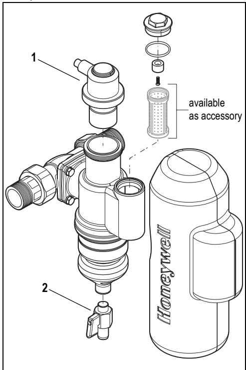
12. Spare Parts
1 Venting insert EE49
2 Ball valve KH49

Use only original spare parts

13. Accessories
PE49 Phosphate cartridge
Phosphate cartridge for protection of the heater system against corrosion.
Use only in heater systems without aluminium materials.
PE49 Cartouche phosphate
Automation and Control Solutions
Honeywell GmbH
Hardhofweg
D-74821 Mosbach
Phone: (49) 6261 810
Fax: (49) 6261 81309
http://europe.hbc.honeywell.com
www.honeywell.com
Manufactured for and on behalf of the
Environmental and Combustion Controls Division of
16, Switzerland by its Authorised Representative Honeywell GmbH
MU1H-1547GE23 R1009
Subject to change
- F
- Functional description
- Application
- Technical data
- Scope of delivery
- Options
- Assembly
- Installations Guidelines
- Installation notes for the quick bleeder
- Installation into pipeline
- Installing the phosphate cartridge (available as an accessory)
- Commissioning
- Inspection
- Maintenance
- Rinse out sludge and air separator
- Clean quick bleeder
- Replace the phosphate cartridge (available as an accessory).
- Cleaning the magnetic separator
- Disposal
- PE49 Phosphate cartridge
- PE49 Cartouche phosphate
- Automation and Control Solutions
Brand : HONEYWELL
Model : HF 49
Category : Descaler