D06FI - Faucets HONEYWELL - Free user manual and instructions
Find the device manual for free D06FI HONEYWELL in PDF.
| Product type | Pressure reducing valve with gauge |
| Brand | HONEYWELL |
| Model | D06FI |
| Compatible fluids | Water, oil-free compressed air, nitrogen |
| Max. inlet pressure | 16 bar (transparent bowl) / 25 bar (brass or steel bowl) |
| Adjustable outlet pressure | 1.5 to 6.0 bar (preset 3 bar) |
| Temperature range | 0 to 40°C (transparent bowl) / 0 to 70°C (brass or steel bowl) |
| Available connections | 1/2" to 2" |
| Filtration fineness | 0.16 mm |
| Operating principle | Spring and diaphragm, upstream pressure compensation |
| Delivery content | Body, fittings, valve seat, fine filter, spring cap, brass bowl, adjusting spring, venturi nozzle (1 1/4" and 2") |
| Available variants | A (transparent), B (brass), E (transparent), etc.; D06F/ D06FH/ D06FN |
| Recommended maintenance | Annual inspection, maintenance every 1 to 3 years |
| Cleaning | Bowl and filter cleanable; do not use solvents or alcohol |
| Main materials | Stainless steel, brass, plastic |
| Accessories | Pressure gauge (M07M), double hexagon key ZR06K, check valve RV277, connection sets VST06 |
| Spare parts | Spring cap assembly, O-rings, strainer bowls (transparent, brass, steel) |
| Compliance | PED directive, DIN 1988 |
| Installation | Horizontal with bowl downward, provide shut-off valves and frost protection |
Frequently Asked Questions - D06FI HONEYWELL
User questions about D06FI HONEYWELL
0 question about this device. Answer the ones you know or ask your own.
Ask a new question about this device
Download the instructions for your Faucets in PDF format for free! Find your manual D06FI - HONEYWELL and take your electronic device back in hand. On this page are published all the documents necessary for the use of your device. D06FI by HONEYWELL.
USER MANUAL D06FI HONEYWELL
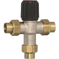
Pressure Reducing Valve
Disconnecteur
Drukreduceerklep
- Follow the installation instructions.
- Use the appliance
according to its intended use
in good condition
with due regard to safety and risk of danger. - Note that the appliance is exclusively for use in the applications detailed in these installation instructions. Any other use will not be considered to comply with requirements and would invalidate the warranty.
- Please take note that any assembly, commissioning, servicing and adjustment work may only be carried out by authorized persons.
- Immediately rectify any malfunctions which may influence safety.
2. Functional description
Spring loaded pressure reducing valves operate by means of a force equalising system. The force of a diaphragm operates against the force of an adjustment spring. If the outlet pressure and therefore diaphragm force fall because water is drawn, the then greater force of the spring causes the valve to open. The outlet pressure then increases until the forces between the diaphragm and the spring are equal again. The inlet pressure has no influence in either opening or closing of the valve. Because of this, inlet pressure fluctuation does not influence the outlet pressure, thus providing inlet pressure balancing.
3. Application
Medium Water, compressed air and nitrogen in consideration of valid standards (e.g. DIN EN 12502)
Inlet pressure max. 16 bar with clear filter bowl max. 25 bar with brass or stainless steel filter bowl
Outlet pressure 1.5-6.0 bar - D06F, D06FI (preset to 3 bar)
0.5-2.0 bar - D06FN (preset to 1.5 bar)
1.5-12.0 bar -D06FH (preset to 5 bar)
0.5-3.0 bar - D06F-1/4ZA (preset to 1 bar) Caution!
In applications where UV radiation and solvent vapours are present, use the SM06T brass filter bowl!

4. Technical data
Operating Maximum 40^ with clear filter bowl temperature Maximum 70^ with brass or stainless st filter bowl
Minimum pressure 1.0 bar (D06F, D06FH, D06FI, D06F-1/4ZA) drop 0.5 bar (D06FN)
Connection size 1 / 2 " - 2" (D06F, D06FH, D06FI, D06FN) 1 / 4 " (D06F-1/4ZA)
As part of an installation being approved according to PED requirements, this product must also be certified.
5. Scope of delivery
The pressure reducing valve comprises:
- Housing with G1/4 pressure gauge connections on both sides
- Threaded male connections (options A & B)
- Valve insert complete with diaphragm and valve seat
- Fine filter with 0.16 mm mesh
- Spring bonnet with adjustment knob and setting scale
Filter bowl - Adjustment spring
- Venturi-nozzle
o D06F, D06FH, D06FI - 11/4" + 2"
o D06FN - 2"
Pressure gauge not included (see accessories)
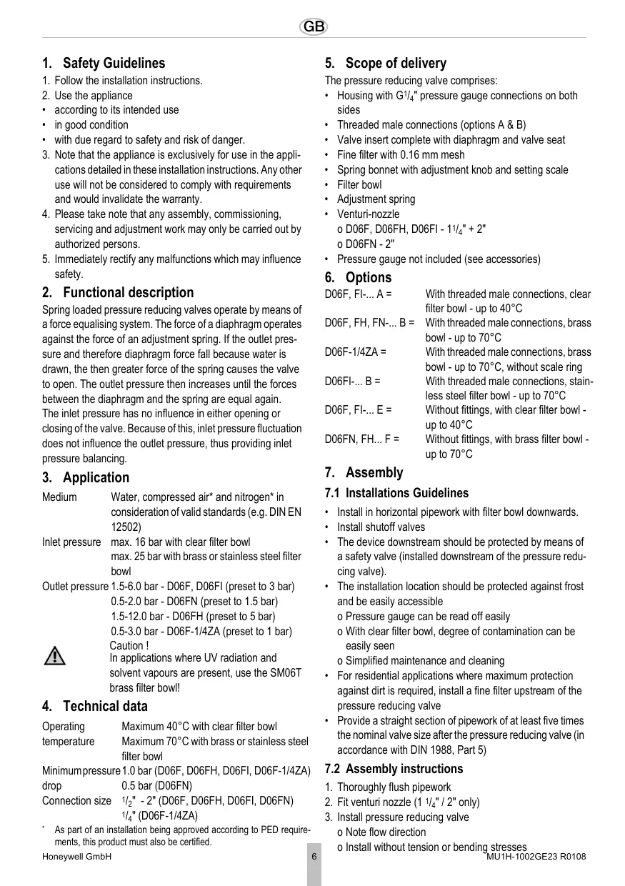
6. Options
D06F, FI... A = With threaded male connections, clear filter bowl - up to 40^
D06F, FH, FN...B = With threaded male connections, brass bowl - up to 70^
D06F-1/4ZA = With threaded male connections, brass bowl - up to 70^ , without scale ring
D06FI-... B = With threaded male connections, stainless steel filter bowl - up to 70^
D06F, FI...E = Without fittings, with clear filter bowl - up to 40^
D06FN, FH... F = Without fittings, with brass filter bowl - up to 70^
7. Assembly
7.1 Installations Guidelines
Install in horizontal pipework with filter bowl downwards.
Installshutoffvalves
- The device downstream should be protected by means of a safety valve (installed downstream of the pressure reducing valve).
- The installation location should be protected against frost and be easily accessible
o Pressure gauge can be read off easily
o With clear filter bowl, degree of contamination can be easily seen
o Simplified maintenance and cleaning
- For residential applications where maximum protection against dirt is required, install a fine filter upstream of the pressure reducing valve
- Provide a straight section of pipework of at least five times the nominal valve size after the pressure reducing valve (in accordance with DIN 1988, Part 5)
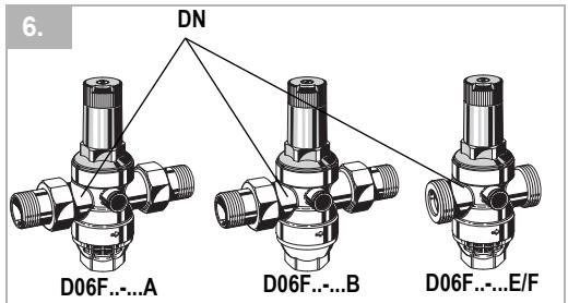
7.2 Assembly instructions
- Thoroughly flush pipework
- Fit venturi nozzle (114'' / 2'' only)
- Install pressure reducing valve o Note flow direction
o Install without tension or bending stresses
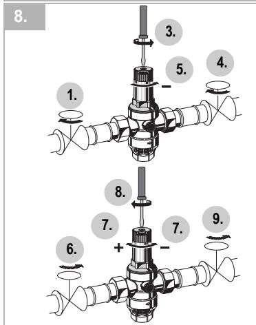
8. Commissioning
8.1 Setting outlet pressure

Set outlet pressure min. 1 bar under inlet pressure.
- Close shutoff valve on inlet
- Release pressure on outlet side (e.g. through water tap)
- Close shutoff valve on outlet
- Loosen slotted screw o Do not remove slotted screw
- Slacken tension in compression spring
o Turn control handle to the left (-) until it does not move any more
- Slowly open shutoff valve on inlet
- Turn control handle until the setting scale shows the desired value
- Retighten slotted screw
- Slowly open shutoff valve on outlet
9. Maintenance

We recommend a planned maintenance contract with an installation company
In accordance with DIN 1988, part 8, the following measures must be taken:
9.1 Inspection

Frequency: once annually
To be carried out by an installation company or the operator.
- Close shutoff valve on outlet
- Check back pressure using a pressure meter when there is zero through-flow
o If the pressure is increasing slowly, the valve may be dirty or defective. In this instance, carry out servicing and cleaning
- Slowly open shutoff valve on outlet
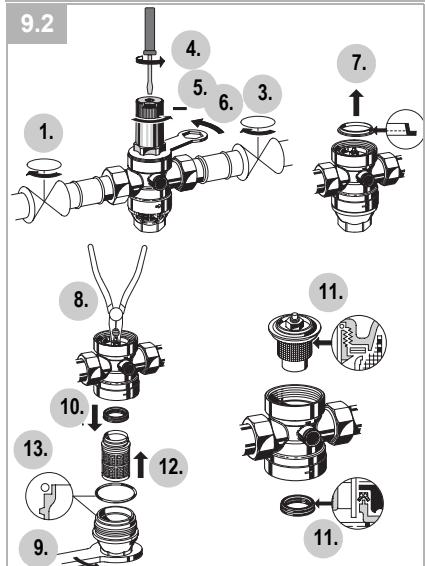
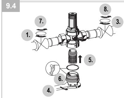
9.2 Maintenance

Frequency: every 1-3 years (depending on local operating conditions)
To be carried out by an installation company
- Close shutoff valve on inlet
- Release pressure on outlet side (e.g. through water tap)
- Close shutoff valve on outlet
- Loosen slotted screw
o Do not remove slotted screw. Caution!

There is a spring in the spring bonnet. It may cause injuries if the spring is derailing.
-
Make sure tension in compression spring is slakkened!
-
Slacken tension in compression spring
o Turn control handle to the left (-) until it does not move any more
- Unscrew spring bonnet
o Use double ring wrench ZR06K
- Remove slip ring
- Remove valve insert with a pair of pliers
- Unscrew filter bowl
o Use double ring wrench ZR06K
10.Remove slotted ring
11. Check that sealing ring, edge of nozzle and slotted ring are in good condition, and if necessary replace the entire valve insert
12.Remove filter, clean and reinsert
- Place O-ring onto filter bowl
14.Reassemble in reverse order
Press in diaphragm with finger before inserting slip ring. Screw in filter cup hand-tight (without tools)
15.Set outlet pressure
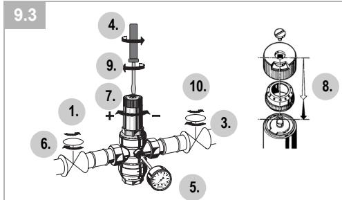
9.3 Adjusting the setting scale
If the adjustment knob is removed, this setting is lost. A new setting can be achieved using a pressure gauge.
- Close shutoff valve on inlet
- Release pressure on outlet side (e.g. through water tap)
- Close shutoff valve on outlet
- Loosen slotted screw
o Do not remove slotted screw
- Fit manometer
- Slowly open shutoff valve on inlet
- Set desired outlet pressure (e.g. 4 bar)
- Align scale (e.g. 4) in middle of viewing window
- Retighten slotted screw
- Slowly open shutoff valve on outlet
9.4 Cleaning

Caution!
Do not use any cleaning agents containing solvents and/or alcohol to clean the plastic parts!
Cleaning agents can lead to water damage!
If necessary, the filter bowl and the filter can be cleaned.

To be carried out by an installation company or the operator.

Detergents must not be allowed to enter the environment or the sewerage system!
- Close shutoff valve on inlet
- Release pressure on outlet side (e.g. through water tap)
- Close shutoff valve on outlet
- Unscrew filter bowl o Use double ring wrench ZR06K
- Remove filter, clean and reinsert
- Place O-ring onto filter bowl
- Screw in filter cup hand-tight (without tools)
- Slowly open shutoff valve on inlet
- Slowly open shutoff valve on outlet
10. Disposal
The pressure reducing valve comprises:
Stainless steel
Steel
Plastic

Observe the local requirements regarding correct waste recycling/disposal!
- Troubleshooting
| Problem | Cause | Remedy |
| Beating sounds | Pressure reducing valve is too large | Call our Technical Customer Services |
| Water is escaping from the spring bonnet | Diaphragm in valve insert is faulty | Replace valve insert |
| Too little or no water pressure | Shutoff valves up- or downstream of the pressure reducing valve are not fully open | Open the shutoff valves fully |
| Pressure reducing valve is not set to the desired outlet pressure | Set outlet pressure | |
| Filter in pressure reducing valve is contaminated | Clean or replace filter | |
| Pressure reducing valve is not fitted in flow direction | Fit pressure reducing valve in flow direction (note direction of arrow on housing) | |
| The outlet pressure set does not remain constant | Filter in pressure reducing valve is contaminated or worn | Clean or replace filter |
| Valve insert, sealing ring or edge of nozzle is contaminated or worn | Replace valve insert | |
| Rising pressure on outlet (e.g. in boiler) | Check check valve, safety group etc. |
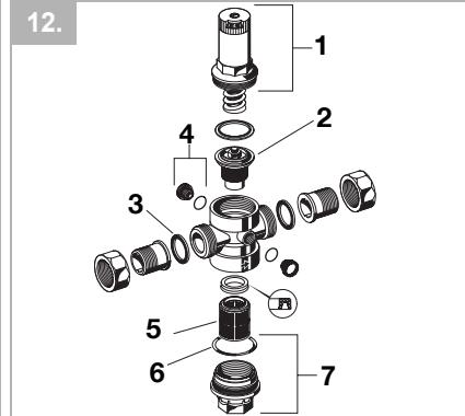
12. Spare Parts
| 1 | Spring bonnet complete | 1/2" + 3/4" | 0901515 |
| with setting scale | 1" + 1/4" | 0901516 | |
| D06F, D06FI | 1/2" + 2" | 0901518 | |
| Spring bonnet complete | 1/2" + 3/4" | 0900227 | |
| with setting scale | 1" + 1/4" | 0900228 | |
| D06FH, D06F-1/4ZA | 1/2" + 2" | 0900229 | |
| Spring bonnet complete | 1/2" + 3/4" | 0900153 | |
| with setting scale | 1" + 1/4" | 0900154 | |
| D06FN | 1/2" + 2" | 0900155 |
| 2 | Valve insert complete | 1/2" + 3/4" | D06FA-1/2 |
| D06F, D06FH | 1" + 11/4" | D06FA-1B | |
| (without filter) | 11/2" + 2" | D06FA-11/2 | |
| Valve insert complete | 1/2" + 3/4" | D06FNA-1/2 | |
| D06FN (without filter) | 1" + 11/4" | D06FNA-1B | |
| 11/2" + 2" | D06FNA-11/2 | ||
| Valve insert complete | 1/2" + 3/4" | D06FI-1/2 | |
| D06FI (without filter) | 1" + 11/4" | D0FI-1 | |
| 11/2" + 2" | D06FI-11/2 |
| 3 Union seal washer (10 pcs.) | 1/2" | 0901443 |
| 3/4" | 0901444 | |
| 1" | 0901445 | |
| 11/4" | 0901446 | |
| 11/2" | 0901447 | |
| 2" | 0901448 |
| 4 | Blanking plug with O-ring R1/4" (5 pcs.) | S06K-1/4 |
| 5 | Replacement filter insert | 1/2" + 3/4" | ES06F-1/2A |
| D06F, D06FI | 1" + 11/4" | ES06F-1B | |
| 11/2" + 2" | ES06F-11/2A | ||
| Replacement filter insert | 1/2" + 3/4" | ES06F-1/2A | |
| D06FH, D06FN | |||
| 1" + 11/4" | ES06F-1A | ||
| 11/2" + 2" | ES06F-11/2A |
| 6 | O-ring set for D06FI | 1/2" + 3/4" | 0901246 |
| (10 pcs.) | 1" + 11/4" | 0901499 | |
| 11/2" + 2" | 0901248 |
| 7 Clear filter bowl | 1/2" + 3/4" | SK06T-1/2 |
| with O-ring | 1" + 11/4" | SK06T-1B |
| D06F, D06FI | 1/2" + 2" | SK06T-11/2 |
| Brass filter bowl | 1/2" + 3/4" | SM06T-1/2 |
| with O-ring | 1" + 11/4" | SM06T-1B |
| D06F, D06FH, D06FN | 1/2" + 2" | SM06T-11/2 |
| Stainless steel filter bowl | 1/2" + 3/4" | SI06T-1/2 |
| with O-ring | 1" + 11/4" | SI06T-1 |
| D06FI | 1/2" + 2" | SI06T-11/2 |
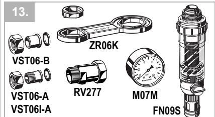
13. Accessories
| FN09S | HABEDO® Retrofit filter Reverse-rinsing filter for retro-conversion to a filter combination unit of pressure reducing valves |
| M07M | Pressure gauge Housing diameter 63 mm, rear connection thread G1/4". Ranges: 0 - 4, 0 - 10, 0 - 16 or 0 - 25 bar. Please indicate upper value of pressure range when ordering |
| ZR06K | Double ring wrench For removal of spring bonnet and filter bowl |
| RV277 | Inlet check valve Available in sizes R1/2" - 2" |
| VST06-A | Connection set Threaded connections |
| VST06-B | Connection set Solder connections |
| VST06I-A | Connection set With stainless steel threaded connections |
| 5 Elément filtrant | 1/2" + 3/4" | ES06F-1/2A |
| D06F, D06FI | 1" + 11/4" | ES06F-1B |
| 11/2" + 2" | ES06F-11/2A | |
| Elément filtrant | 1/2" + 3/4" | ES06F-1/2A |
| D06FH, D06FN | 1" + 11/4" | ES06F-1A |
| 11/2" + 2" | ES06F-11/2A |
D06F, D06FH (sin filtro) 1^ + 11 / _4^ D06FA-1B
11 / 2'' + 2'' D06FA-11/2
Conjunto de valvula interna 1 / 2^ + 3 / 4^ D06FNA-1/2
D06FN (sin filtro) 1^ + 1^1 / 4 D06FNA-1B
112 + 2 D06FNA-11/2
Conjunto de valvula interna 1 / 2^ + 3 / 4^ D06FI-1/2
D06FI (sin filto) 1^ + 1 / 4 D06FI-1
11/2" + 2" D06FI-11/2
- C6bI0daIte HNcTpkyuHIO moHTaJy.
2.Исплььтей пибор
- NO Ha3HaueHnIO
B INCnpaBHOM TEXHnueCKOM COCTOHRN
Cc6bIIOeHnEMTexHKn 6e3OanchoCTN
3.Heo6xOJMo yueTb, YTO np60pnpEHa3HaueH IINIcNoB3OBaHHN NCKJIHOHTeJIbHO B O6nlaCTn, yKa3aHHoB DAHHo INCHTpKuIM NO MOHTaKy. HNOE INBbIXoJDAEE 3a pAMKn yKa3aHHORO INCIOJIb3OBAHHe CCHTaTeCt HeHaJNeJexaUIM.
4.Bce pa6oTbI NO MOHTaKy DoJIxHbI IpnOIN3BOIDNTbC RcNlAmn TOJbKO KBaInΦuINPOBaHOrO TexnepcOHana
5. HemeJeHno yctpaHnTe HeNCpabHocTn, KOtOpbIe MOyT HApUuNTb 6e3OnaChOCTb pa6oTbl.
2.Описане pa60ть
IpyxHHbIe peyKTopbl paobTaIO T NO CnCTMe cpaBHeHnA CNL. B IpoTNUBOEc CNIe Mem6paHbl DeiCTByET CNla HATxKeHnI pyxHbI peryuPBOUCHOro KlanAna. EcIn B pe3yNbTaTe BOO3aOpBa DaJIeHne Ha BbIXOe (DaBNeHne 3a peyKTopOM) yMeHbShaetCnI TEM CaMbIM yMeHbShaetCnla Me6paHbl, To 60JIbShaCnla HATxKeHnI pyxHbI bOTKpbIBaET KlanAna. DabJIeHne Ha BbIXOe CTahOBHTCn CHOba BbIe, NOKa He 6bET DOCTMHyTO paBHObECHOE COCTOHNe MEXdy CNIOI MEM6paHbl n CNIOI HA TAYKeHnI pyxHbIb.
BxodHoe (xCxodHoe) daBHe Hne He BnIaReT ha peryunpyuOsi knapanB peDyKTope. Kone6aHna daBHeNHa CTOpOHe BXoJa He BnIaOT Ha KOHeHoe daBLeHne (KOMPehCaunia CXoDHoro daBHeNHa).
3. Ппимен.
Cpeja BOJa, He cOePkauni MaCn aCxTaBIO3DyX* n a30T* C yUeTOM PnAHOBbIX HOpM (HanpImep, DIN EN 12502)
IcxoHoe MACK.16 6ap, npo3paHna cHTOBa
dABNeHne yauka
MACK.25 6ap, naTyHHa cHTOBa yauka
MACK.25 6ap, c cetTuToy uauJe n3
BbICOKKaueCTBeHNo CTANI
OkoHcTeJI1.5-6.0 6ap - D06F, D06FI
bHoe (IpeDyCTaHOBHeHnHa 3 6ap)
ДаВлени 0.5-2.0 бap - D06FN
(П配电ТановЛевно Ha 1,5 6ap)
1.5-12.0 6ap - D06FH
(П配电иовлелноha56ap)
0.5-3.0 6ap - D06F-1/4ZA
(П配电ТановЛевно Ha 1 6ap)
Octopokno! B 30Hax C yIbTaΦnOJeTOBbIM ObnyeHnEM n napampactBOpneJr Heo6xOdImo NCNoB3OBAtB cTeuTyO uAuyi N3 BBICOKOKaueCTBeHHoI CTAn SI06T!
4. TexHnueckne xapaKTePnCTnKn
Pa6o7a MaKc. 40^ ,IatyHna CnTobar YaaKa TMnepaTypa MaKc. 70^ ,IatyHna CnTobar YaAka MaKc. 70^ , c cTeTuToY aUeN 3 BbICOKKaueCTBeHHO CTaII
MnHmMaJIbHbI1.06ap (D06F,D06FH,D06FI, n nepenad D06F-1/4ZA)
BbICOKOKaYeCTBeHHoN CTaNN Do 70^
D06F, FI...E = 6e3 pe3b60BbIX COeINHeHn, c npo3paunOH CNTOBOW qaWKoJ do 40^
D06FN, FH-... F = 6e3 pe3b6obBix coeINHeHn, NaTyHHa cHTOBa YaShka Do 70^
7. Mohtak
7.1 YCTaHOBKG
- UctaHOBka B rOpn3oHTaIbHbI Tpy6oPBOO, CTOBOU YaIkoB BHN3
- PnpeDycmOTpeTb 3anOpHbIe KJIanaHbI
3aunTa nocLenyUoSey UcTaHOBKn npedoxpaHnTeNbHbIM KnAnaHOM (ycTaHOBKa nocIpepeyKTopa) - MecTo yCTaHOBKn DoJIxKHo 6bITb 3aIuIeHo OToMopo3a N IeRKO DoCTyNtHO
O MaHOMeTp DoJXKeH 6bIb XopoIo DoCTyneH dIra Na6IIIODeHnA
OCTeNEH3aqr3HeHnB CcIyae np03paHNo CNTOBo YaWKn DOJXHa 6bITb XopoIO BnHa OYnpOuEHHoe TexHnueckoe ObcIyKnBaHne n OONCtKa
Bcnyae yctaHOBN DOMOBBO BODONPOBO, rHe Heo6xOIMMa BbICOKa CTeNEHb 3aunTbOT 3aqr3neHnI, npeD peyKTopOM DOJKeH 6bITb yCTaHOBEn FInbTp TOHKO ONUCTKN
- PpeDyCMOTpeb nocle peDyKtopa yCnOKoNTeBHy bYacTcK 5xDN (B COOTBeCTBn C DIN 1988, YAcTb 5)
UCTaHOBNTb DaBHeHne Ha BbIXOe OKo1o 16ap npn HauHnHn DaBHeHnHa BxOe.
1.3aKpbItb 3anOpHyo apMaTyp
2.CHrTb DaBHeHne Ha CToPoHE BbIXOa (HaNPIMep, C NOMOUsbO BoDraHOu ZaIΦbI)
3. 3akpbItb 3anOpHyo apMaTypy
4.OcnaBntb BnHT cIJIuCEBOI roJOBKO. OHe BbIKpyUHbTaB BnHT C IJIuCEBOI rOJOBKO
5.Ocna6ntb HaxnMHy npyKnHy oPiobepHybpyKy BneBO(-)
6. MeDnEHH OTKpbIb 3aOpHyIO
7.Поворачватуку,пoka нашкалустоноки не появпстая тpeбуемо зсанения.
8. ChOBA 3aTMyTb BnHT C WJIInCeBOI rOJIOBKOI
9. MeDneHNO OTKpbItb 3aOpHyIO
9. yxoid

PekomeHnyem 3akJIOUHTb DOROBOPo6
06cIyKINBaHN CO cIeCapHO
caHTexHnueckIM IpeInpnTneM
B COOTBeTCTBmC DIN 1988, uactb 8 Heo6xoJIMOpnoBOOHTcJeDyUOuIe MePOnpNtTn:
9.1 OcmOTP

YnCTaIe CpeIcTBA He DOnJXbI NonaTb B OkpyKaUOyU OpeDy IIN KaHaJIIn3aUIO!
1.3aKpbItb 3anOpHyio apMaTypy
2.CnTb DaBHeHne Ha CTOpOHe BbIXoDa (HaPnIMep, C NOMOuHO BOyHOu YaIΦbI)
3.3akpbblT 3anopHyo apMaTypy
4. OTBnHTntb CNTOBYu yaShky. OICNoJIb3OBAtB DBOHOn KOJIbCeBOI KJIHOZ R06K
5.BbHtB CHTO, OCHNTb IN CHOBA BCTaBtB
6. BCTaBntb yIINOTHnTeIbHoe KOJIbQo KpyrIoro CeYeHnHa CITOByU YaIky
7.CnIbHO BBNHTNb CNTyauTyu YaU (6e3 INHCTpyMeHTa)
8. MeДлЕнно OTKpbIbT 3aInOpHyIO
9. MeДлЕнно OТКрьтВ 3anOpHyIO
10.Ytuln3aun
PeDyKTOp DaBJIeHnIcoCTOnT n3:
- BbICOKOKaueCTBeHHa CTaNb
CTaJIu - PJIaCTMaCCbI

Co6IIOaTb MeCTHbIe IpeDncaHnno ytnnn3aun nn yctpaHEno OTxoOBo!
11.HencpaBnOCTn /ycTpaHeHne
| 5 3aapanchoe cnto D06F, D06FI | 1/2" + 3/4" | ES06F-1/2A |
| 1" + 11/4" | ES06F-1B | |
| 11/2" + 2" | ES06F-11/2A | |
| 3apanchoe cnto D06FH, D06FN | 1/2" + 3/4" | ES06F-1/2A |
| 1" + 11/4" | ES06F-1A | |
| 11/2" + 2" | ES06F-11/2A |
| 6 Komplèkt koleuc | 1/2" + 3/4" | 0901246 |
| κργινοτο ευεηνησε | 1" + 1/4" | 0901499 |
| (10 υτυκ) | 1/2" + 2" | 0901248 |
| 7 | Празчая ситовая 1/2" + 3/4" | SK06T-1/2 |
| Чашka с кольцом 1" + 11/4" | SK06T-1B | |
| Крurusю сеоня 11/2" + 2" | SK06T-11/2 | |
| D06F, D06FI |
| 5 | Yedek)süzgeç | 1/2" + 3/4" | ES06F-1/2A |
| D06F, D06FI | 1" + 11/4" | ES06F-1B | |
| 11/2" + 2" | ES06F-11/2A | ||
| Yedek)süzgeç | 1/2" + 3/4" | ES06F-1/2A | |
| D06FH, D06FN | 1" + 11/4" | ES06F-1A | |
| 11/2" + 2" | ES06F-11/2A |
| 6 D06FI écin halka conta 1/2" + 3/4" seti 1" + 1/4" (10 adet) | 0901246 |
| 0901499 | |
| 0901248 |
| 7 Saydamsciousçtasi | 1/2" + 3/4" | SK06T-1/2 |
| halka contali | 1" + 1/4" | SK06T-1B |
| D06F, D06FI | 1/2" + 2" | SK06T-11/2 |
| Küstahliksciousçtasi | 1/2" + 3/4" | SM06T-1/2 |
| halka contali | 1" + 1/4" | SM06T-1B |
| D06F, D06FH, D06FN | 1/2" + 2" | SM06T-11/2 |
| D06FI icin halka | 1/2" + 3/4" | SI06T-1/2 |
| contali paslanmaz | 1" + 1/4" | SI06T-1 |
| çeliktensciousçtasi | 1/2" + 2" | SI06T-11/2 |
13.Aksesuarlar
Automation and Control Solutions
Honeywell GmbH
Hardhofweg
D-74821 Mosbach
Phone: (49) 6261 810
Fax: (49) 6261 81309
http://europe.hbc.honeywell.com
www.honeywell.com
Manufactured for and on behalf of the
Environmental and Combustion Controls Division of
Honeywell Technologies Sàrl, Ecublens, Route du
Bois 37, Switzerland by its Authorised Representative Honeywell GmbH
MU1H-1002GE23 R0108
Subject to change
© 2007 Honeywell GmbH
Honeywell
D
- Safety Guidelines 6
- Functional description
- Application
- Technical data
- Scope of delivery
- Options
- Assembly
- Commissioning
- Maintenance
10.Disposal
11.Troubleshooting
12.Spare Parts - Accessories