BA295 - Faucets HONEYWELL - Free user manual and instructions
Find the device manual for free BA295 HONEYWELL in PDF.

| Product Type | Backflow Preventer (Type BA) |
| Brand | Honeywell |
| Model | BA295 |
| Connection Sizes | 1/2" (DN15), 3/4" (DN20), 1" (DN25), 1-1/4" (DN32), 1-1/2" (DN40), 2" (DN50) |
| Maximum Inlet Pressure | 10.0 bar |
| Minimum Inlet Pressure | 1.5 bar |
| Maximum Operating Temperature | 65°C |
| Installation Position | Horizontal with discharge valve downwards |
| Medium | Water |
| Scope of Delivery | Housing with integral strainer (0.6 mm mesh), valve cartridge with integral check valve and discharge valve, outlet check valve, three ball valves for differential pressure gauge, connection fittings, discharge connection |
| Options | BA295-…A (threaded connections 1/2", 3/4", 1-1/2", 2"), BA295-…B (threaded connections 1", 1-1/4") |
| Maintenance Frequency | Inspection every 6 months; maintenance every 1-3 years |
| Discharge Pipe Size | DN50 for 1/2" to 1" connections; DN70 for 1-1/4" to 2" connections |
| Accessories | D06F Pressure Reducing Valve, TK295 Test Kit (digital), TKA295 Test Kit (analogue), F76S Fine Filter |
| Spare Parts | Cartridge insert, check valve complete, lip seal, O-rings |
| Materials | Red bronze housing, high-quality synthetic valve cartridge, brass ball valves, elastomer sealing elements |
| Standards | DIN EN 1717 |
Frequently Asked Questions - BA295 HONEYWELL
User questions about BA295 HONEYWELL
0 question about this device. Answer the ones you know or ask your own.
Ask a new question about this device
Download the instructions for your Faucets in PDF format for free! Find your manual BA295 - HONEYWELL and take your electronic device back in hand. On this page are published all the documents necessary for the use of your device. BA295 by HONEYWELL.
USER MANUAL BA295 HONEYWELL
Keep instructions for later use!
DN15, DN20, DN25 RV295-1/2E
DN32, DN40, DN40 RV295-11/4E

12. Zubehör
D06F Druckminderer
- Follow the installation instructions.

The factory-set position of the ball valves may not be altered. Non-compliance with this instruction will make any warranty claims null and void.
- Use the appliance
according to its intended use
- in good condition
with due regard to safety and risk of danger.
3. Note that the appliance is exclusively for use in the applications detailed in these installation instructions. Any other use will not be considered to comply with requirements and would invalidate the warranty.
4. Please take note that any assembly, commissioning, servicing and adjustment work may only be carried out by authorized persons.
5. Immediately rectify any malfunctions which may influence safety.
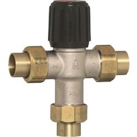
2. Functional description
BA type backflow preventers are divided into three pressure zones. The pressure in zone ① is higher than in zone ②, which in turn is higher than in zone ③. A discharge valve is connected to zone ② which opens at the latest when the differential pressure between zones ① and ② falls to 0.14 bar. The water from zone ② discharges to atmosphere. In this way the danger of back pressure or back syphonage into the supply network is prevented. The pipework connection is interrupted and the drinking water network is protected.
3. Application
| Medium | Water |
| Maximum inlet pressure | 10.0 bar |
| Minimum inlet pressure | 1.5 bar |
4. Technical data
Installation position Horizontal with discharge valve downwards
Max. operating temperature 65°C
Discharge pipe DN50 for connection sizes 1 / 2^ - 1^ connection DN70 for connection sizes 1 / 4'' - 2'' Connection size 1 / 2^ - 2^
5. Scope of delivery
The backflow preventer consists of:
Housing
- Integral strainer, mesh size approx. 0.6 mm
- Valve cartridge with integral check valve and discharge valve
- Outlet check valve
- Three ball valves for the connection of a differential pressure gauge
- Connection fittings
- Discharge connection
6. Options
| BA295-… A = | Standard version with threaded |
| connections1/2", 3/4", 11/2" und 2" | |
| BA295-… B = | Standard version with threaded |
| connections | |
| 1" and 11/4" | |
| Connection size | |
7. Assembly
7.1 Installations Guidelines
- Install shutoff valves before and after backflow preventer
Install in horizontal pipework with the discharge valve downwards - Ensure good access
- Simplifies maintenance and inspection
- Backflow preventers of this type have an integral strainer which protects the device from the ingress of dirt. With highly polluted water a fine filter should be installed upstream to ensure the correct function of the device.
- Do not install in places where flooding can occur
- The installation environment should be protected against frost and ventilated well
- Install discharge pipework which has adequate capacity
Use and type of installation according to DIN EN 1717
7.2 Assembly instructions
- Thoroughly flush pipework
- Install backflow preventer
Install in horizontal pipework with discharge connection directed downwards
Note flow direction (indicated by arrow) o Install without tension or bending stresses
- Provide a straight section of pipework of at least five times the nominal valve size after the backflow preventer
- Attach drain pipe to discharge connection (plastic pipe HT 50, HT70)
- The appliance is ready for use
8. Maintenance

We recommend a planned maintenance contract with an installation company

Maintenance of backflow preventer must be carried out by authorized personnel!
8.1 Inspection

- Frequency: every 6 month (depending on local operating conditions)
- To be carried out by an installation company
Inspection with a test control unit and maintenance-set (see accessories)
8.1.1 Testing discharge valve

Take note of the instructions of the test control unit TKA295 or TK295
- Procedure according to instruction of the test control unit TKA295 resp. TK295

Quick test for the discharge valve:
- Lower the inlet pressure o if the discharge valve opens (it drops), the function is o.k.
8.1.2 Testing outlet check valve

Take note of the instructions of the test control unit TKA295 or TK295
- Procedure according to instruction of the test control unit TKA295 resp. TK295
8.2 Maintenance

We recommend a planned maintenance contract with an installation company
In accordance with DIN EN 1717 a regular maintenance must be taken.

Frequency: every 1-3 years (depending on local operating conditions)
To be carried out by an installation company
8.2.1 Cartridge insert
- Close shutoff valve on inlet
- Release pressure on outlet side (e.g. through water tap)
- Close shut off valve on outlet
- Remove cover
- Replace cartridge insert and lip seal

-
Don't disassemble cartridge insert to individual parts!
-
Reassemble in reverse order o push down the cartridge insert till it snaps in
- Test function (see chapter inspection)
8.2.2 Check valve
- Close shutoff valve on inlet
- Release pressure on outlet side (e.g. through water tap)
- Close shut off valve on outlet
- Remove cover
- Exchange check valve
- Test function (see chapter inspection)
8.3 Cleaning

- To be carried out by an installation company
To be carried out by the operator
If necessary, the cartridge insert can be cleaned.

Do not use any cleaning agents containing solvents and/or alcohol to clean the plastic parts!

Detergents must not be allowed to enter the environment or the sewerage system!
- Close shutoff valve on inlet
- Release pressure on outlet side (e.g. through water tap)
- Close shut off valve on outlet
- Remove cover
- Clean or replace cartridge insert and lip seal

-
Don't disassemble cartridge insert to individual parts!
-
Reassemble in reverse order o push down the cartridge insert till it snaps in
- Test function (see chapter inspection)
9. Disposal
Red bronze housing
High-quality synthetic material valve cartridge
- High-quality synthetic material or red bronze check valves
- Brass ball valves
Sealing elements made of elastomer materials suitable for drinking water
- Discharge connection
DN15-25 High quality synthetic material
DN32-50 Red bronze

Observe the local requirements regarding correct waste recycling/disposal!
10. Troubleshooting
| Disturbance | Cause | Remedy |
| Discharge valve opens without apparent reason | Pressure strokes in water supply system | Install a pressure reducing valve upstream the backflow preventer |
| Fluctuating inlet pressure | Install a pressure reducing valve upstream the backflow preventer | |
| Cartridge insert is contaminated | Remove cartridge insert and exchange it | |
| Discharge valve don’t close | Deposits on valve seat | Remove cartridge insert and clean or exchange it |
| Damaged ‘o’ring | Remove cartridge insert and exchange it | |
| Leaky discharge valve | Remove cartridge insert and clean or exchange it | |
| Flow is to low | Inlet strainer is blocked | Remove strainer and clean it |
11. Spare Parts
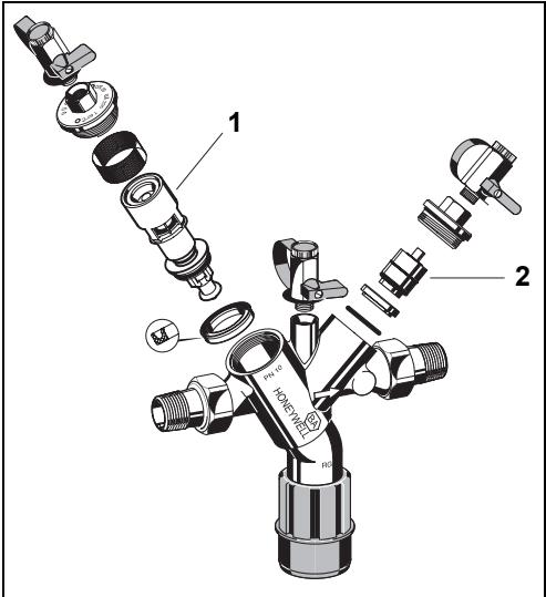
No.Description
Part No.
| 1 | Cartridge insert | 1/2" - 1" | 0903733 |
| complete | 1/4" - 2" | 0903745 |
2 Check valve complete with
Check valve cone and spring made of red bronze
DN15, DN20, DN25 up to 05/06 RV295-1/2
DN32, DN40, DN50 up to 05/06 RV295-11/4
Check valve cartridge with adapter ring
DN15 up to 02/09 RV295-1/2
DN20 up to 10/08 RV295-1/2
DN25 up to 12/08 RV295-1/2
DN32 up to 08/08 RV295-11/4
DN40, DN50 up to 05/09 RV295-11/4
Check valve cartridge without adapter ring
DN15, DN20, DN25 RV295-1/2E
DN32, DN40, DN40 RV295-11/4E
12. Accessories
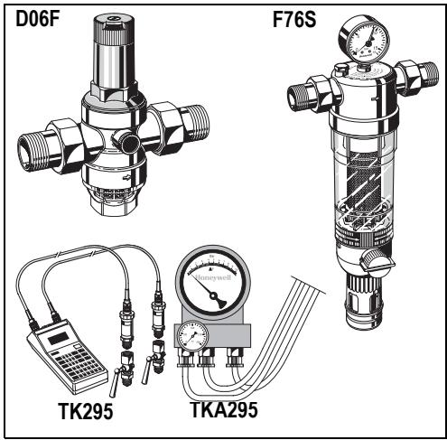
D06F Pressure reducing valve
Noise protected pressure reducing valve with setting scale. Maximum inlet pressure 16 bar, with brass filter bowl 25 bar, outlet pressure range 1.5 - 6.0 bar
A = With clear filter bowl up to 40^ / 16 bar
B = With brass filter bowl up to 70^ / 25 bar
TK295 Test kit
Electronic pressure measuring device with digital indicator, battery-operated.
With case and accessories, ideal for inspection and maintenance of backflow preventer type BA.
TKA295 Test kit
Analogue pressure measuring device with differential pressure display.
With case and accessories, ideal for inspection and maintenance of backflow preventer type BA.
F76S Fine filter, reverse rinsable
AA= With clear filter bowl
AAM= With red bronze filter bowl
DN15, DN20, DN25 a 05/06 RV295-1/2
DN32, DN40, DN50 a 05/06 RV295-11/4
DN15, DN20, DN25 RV295-1/2E
DN32, DN40, DN40 RV295-11/4E
12. Accessori

DN15, DN20, DN25 05/06 asti RV295-1/2
DN32, DN40, DN50 05/06 asti RV295-11/4
DN15, DN20, DN25 RV295-1/2E
DN32, DN40, DN50 RV295-11/4E

12. Lisātarvikkeet
DN15, DN20, DN25 RV295-1/2E
DN32, DN40, DN40 RV295-11/4E

12. Tilbehør
D06F Trykreduktion
Automation and Control Solutions
Honeywell GmbH
Hardhofweg
D-74821 Mosbach
Phone: (49) 6261 810
Fax: (49) 6261 81309
http://europe.hbc.honeywell.com
www.honeywell.com
Manufactured for and on behalf of the
Environmental and Combustion Controls Division of
Honeywell Technologies Sàrl, Rolle, Z.A. La Pièce 16,
Switzerland by its Authorised Representative Honeywell GmbH
ENOH-1220GE23 R0809
Subject to change
- Safety Guidelines 6
- Functional description 6
- Application 6
- Technical data 6
- Scope of delivery 6
- Options 6
- Assembly 6
- Maintenance 7
- Disposal 8
- Troubleshooting 8
- Spare Parts 9
- Accessories 9