NK 295C - Faucets HONEYWELL - Free user manual and instructions
Find the device manual for free NK 295C HONEYWELL in PDF.
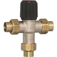
| Product type | Filling combination (system separator, pressure reducer, and integrated shut-off valve) |
| Brand | HONEYWELL |
| Model | NK 295C |
| Category | Valves |
| Mounting position | Horizontal, drain connection downward |
| Max operating temperature | 65°C |
| Drain connection | HT 40 (plastic pipe) |
| Connection dimensions | 1/2" AG |
| Permissible fluid | Water without inhibitors |
| Liquid category | 3 (low toxicity) |
| Disconnector type | CA (conforming to DIN EN 1717) |
| Body material | Dezincification-resistant brass |
| Seal material | NBR |
| Spring material | Spring steel |
| Insulating jacket | Expanded polypropylene |
| Integrated filter basket | Yes, mesh ~0.5 mm |
| Main function | Protection against backflow (pressure, flow, siphonage) and downstream pressure regulation |
| Disconnector maintenance interval | Once a year |
| Pressure reducer maintenance interval | Once a year |
| Max upstream pressure | Not specified in the manual, but typically 16 bar (estimate) |
| Downstream pressure adjustment range | Adjustable as needed (indicated on manometer) |
Frequently Asked Questions - NK 295C HONEYWELL
User questions about NK 295C HONEYWELL
0 question about this device. Answer the ones you know or ask your own.
Ask a new question about this device
Download the instructions for your Faucets in PDF format for free! Find your manual NK 295C - HONEYWELL and take your electronic device back in hand. On this page are published all the documents necessary for the use of your device. NK 295C by HONEYWELL.
USER MANUAL NK 295C HONEYWELL
Keep instructions for later use!
- Follow the installation instructions.
- Use the appliance
according to its intended use - in good condition
with due regard to safety and risk of danger. - Note that the appliance is exclusively for use in the applications detailed in these installation instructions. Any other use will not be considered to comply with requirements and would invalidate the warranty.
- Please take note that any assembly, commissioning, servicing and adjustment work may only be carried out by authorized persons.
- Immediately rectify any malfunctions which may influence safety.
2. Functional description
The refilling combination combines backflow preventer, pressure reducing valve and ball valves in one appliance.
The backflow preventer is a safety device in accordance with EN 1717 to protect systems against back pressure, back flow and back syphonage of non-potable water into service pipe, plants and equipments.
The backflow preventer is separated in three chambers (inlet, middle and outlet chamber).
If no water is drawn from the downstream system, the backflow preventer is in normal position. The up- and downstream check valves and the discharge valve are closed.
If water is drawn from the downstream system, the backflow preventer is in flow position. The check valves up- and downstream are opened and the discharge valve is closed.
If the differential pressure between middle and inlet chambers is less than 10% of the inlet pressure, the system disconnector moves into disconnect position (back suction). The inlet side backflow preventer closes and the discharge valve opens.
There is no possibility to control the safety function by measuring.
The pressure reducing valve reduces the pressure on the inlet side (admission pressure) to the level of the desired pressure on the outlet side (outlet pressure) in individual cases.
Spring-loaded pressure reducing valves work accor
ding to a system of force balance. The piston force works against the spring force of the control valve. If the outlet pressure (back pressure) drops as a consequence of drawing water, leading to the piston force dropping as well, the now greater spring force will open the valve. The outlet pressure is higher again until the balance between piston and spring force is once again achieved.
The inlet pressure has no influence in either opening or closing of the valve. Because of this, inlet pressure fluctuation does not influence the outlet pressure, thus providing inlet pressure balancing.
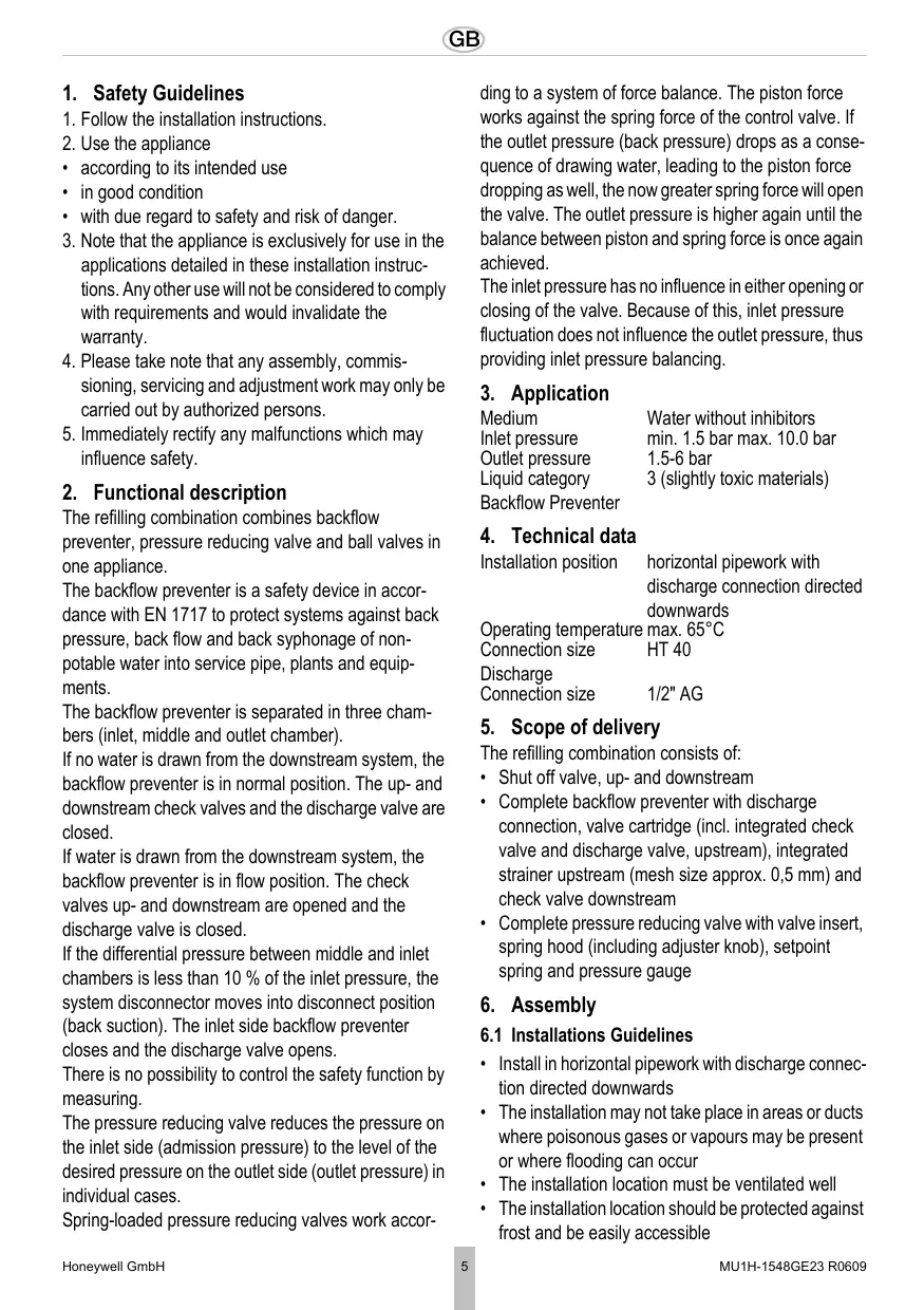
3. Application
| Medium | Water without inhibitors |
| Inlet pressure | min. 1.5 bar max. 10.0 bar |
| Outlet pressure | 1.5-6 bar |
| Liquid category | 3 (slightly toxic materials) |
| Backflow Preventer |
4. Technical data
| Installation position | horizontal pipework with discharge connection directed downwards |
| Operating temperature max. 65°C | |
| Connection size | HT 40 |
| Discharge | |
| Connection size | 1/2" AG |
5. Scope of delivery
The refilling combination consists of:
- Shut off valve, up- and downstream
- Complete backflow preventer with discharge connection, valve cartridge (incl. integrated check valve and discharge valve, upstream), integrated strainer upstream (mesh size approx. 0,5 mm) and check valve downstream
- Complete pressure reducing valve with valve insert, spring hood (including adjuster knob), setpoint spring and pressure gauge
6. Assembly
6.1 Installations Guidelines
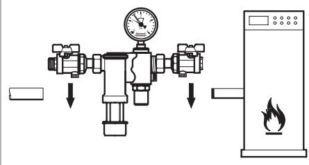
Install in horizontal pipework with discharge connection directed downwards
- The installation may not take place in areas or ducts where poisonous gases or vapours may be present or where flooding can occur
- The installation location must be ventilated well
- The installation location should be protected against frost and be easily accessible
o Simplified maintenance and cleaning
o Pressure gauge at the pressure reducing valve can be read off easily
- Provide a straight section of pipework of at least five times the nominal valve size after the pressure reducing valve (in accordance with DIN 1988, Part 5)
- The refilling combination has an integrated strainer - no separate strainer necessary
o Refilling combination is protected against malfunction and corrosion damage resulting from ingress of foreign bodies, e.g. welding beads, sealing materials, metal cuttings and rust
6.2 Assembly instructions

To avoid stagnating water, the refilling combination must be connected as directly as possible to the supply line!
The guidelines of drinking water regulations apply for installation!
- Thoroughly flush pipework
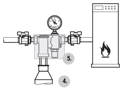
- Remove the isolation shell
- Install refilling combination
Install in horizontal pipework with discharge connection directed downwards
Note flow direction (indicated by arrow) o Install without tension or bending stresses
- Attach drain pipe to discharge connection (plastic pipe HT 40)
- Install isolation shell
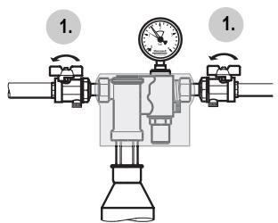
7. Commissioning
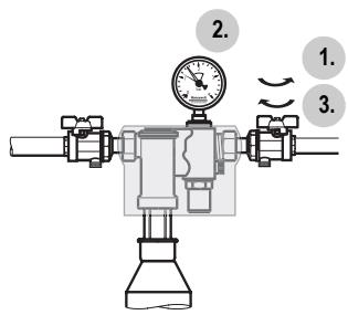
7.1 Setting outlet pressure
- Close shut off valve on inlet and outlet
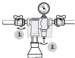
- Slacken tension in compression spring o Insert the available adjuster knob and turn to the left
- Open and close drain cock at the shut off ball valve downstream.
Pressure reducing valve is decompressed.
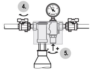
- Slowly open shutoff valve on inlet
- Turn adjuster knob until the manometer shows the desired value.
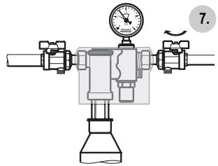
- Remove adjuster knob
- Slowly open shutoff valve on outlet
8. Maintenance

We recommend a planned maintenance contract with an installation company
In accordance with DIN EN 1717 a regular maintenance must be taken.
8.1 Inspection
8.1.1 Pressure reducing valve

Interval: once a year
To be carried out by an installation company or the operator.
- Close ball valve on the outlet side of the refilling combination
- Check outlet pressure on pressure gauge when no flow is occurring
o If the pressure is increasing slowly, the valve may be dirty or defective. In this instance, carry out servicing and cleaning
- Slowly open the ball valve on the outlet side of the refilling combination
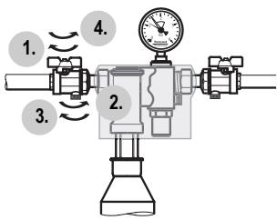
8.1.2 System disconnector

Interval: once a year
To be carried out by an installation company or the operator.
- Close shutoff valve on inlet
- Open the drain point on the inlet side of the shut-off ball valve.
o If the differential pressure between middle and inlet chambers is less than 10% of the inlet pressure, the system disconnector moves into disconnect position (back suction). The inlet side backflow preventer closes and the discharge valve opens.

Does not open the discharge valve Replace refilling combination!
- Close the drain point on the inlet side of the shut-off ball valve
- Slowly open shutoff valve on inlet
8.1.3 Leak-tightness
Interval: once a year To be carried out by an installation company or the operator.
- Open sampling point. Refilling combination changes into flow position.
- Optical control refilling combination of location and tightness.
If water exits at the refilling combination, call the technical customer support service!
9. Disposal
- Dezincification-resistant brass housing
- Discharge connection, valve cartridge, valve insert and spring hood in high-grade synthetic material
High-grade synthetic material check valve
Seals in NBR
Spring steel adjustment spring - Isolation shell in EPP

Observe the local requirements regarding correct waste recycling/disposal!
10. Troubleshooting
| Problem | Cause | Remedy |
| Beating sounds | Non return valve is faulty | Call our Technical Customer Services |
| Water is escaping from refilling combination | Sealing elements are contaminated or worn | Call our Technical Customer Services |
| No or too small water flow rate | Refilling combination is not fitted in flow direction | Fit refilling combination in flow direction (note direction of arrow on housing) |
| Ball valves up- or downstream of refilling combination are not fully open | Open ball valves entirely | |
| Drain cocks at the shut off ball valves up- and downstream of the refilling combination are not fully close | Close drain cocks | |
| Pressure reducing valve is not set to the desired outlet pressure | Set outlet pressure | |
| Refilling combination change not into flow position | Check supply pressure with reaction pres-sure | Call our Technical Customer Services |
| Refilling combination opens and closes in short time intervals (pump) | plant downstream leaky | Check plant |
| Non return valve is contaminated or worn | Call our Technical Customer Services |
Méodium voda bez inhibitoru
Automation and Control Solutions
Honeywell GmbH
Hardhofweg
D-74821 Mosbach
Phone: (49) 6261 810
Fax: (49) 6261 81309
http://europe.hbc.honeywell.com
www.honeywell.com
Manufactured for and on behalf of the
Environmental and Combustion Controls Division of
16, Switzerland by its Authorised Representative Honeywell GmbH
MU1H-1548GE23 R0509
Subject to change
© 2007 Honeywell GmbH
Honeywell
6.2
7.1
8.1.1
8.1.2
D
- Safety Guidelines 5
- Functional description 5
- Application 5
- Technical data 5
- Scope of delivery 5
- Assembly 5
- Commissioning 6
- Maintenance 6
- Disposal 7
- Troubleshooting 7