AM100C1070 - Faucets HONEYWELL - Free user manual and instructions
Find the device manual for free AM100C1070 HONEYWELL in PDF.

| Product Type | AM-1 Series Thermostatic Mixing Valve |
| Brand | Honeywell |
| Model | AM100C1070 |
| Cold Water Inlet Temperature Range | 4 °C to 27 °C (39 °F to 80 °F) |
| Hot Water Inlet Temperature Range | 49 °C to 82 °C (120 °F to 180 °F) |
| Outlet Temperature Range (Model C) | 21 °C to 49 °C (70 °F to 120 °F) |
| Outlet Temperature Range (Standard Model) | 21 °C to 63 °C (70 °F to 145 °F) |
| Maximum Working Pressure | 11034 kPa (150 psi) |
| Body Material | Nickel-Plated Brass |
| O-Rings | EPDM |
| Lead-Free Compliance | Weighted average lead content < 0.25% |
| Certifications | ASSE 1017, CSA, IAPMO |
| Connections | NPT, Union fittings, Solder, PVC-C, Propress, Compression, PEX |
| Flow Path Type | Direct (hot and cold water on same level) |
| Included Accessories | Thermometer adapter, heat tape (depending on model) |
| Thermometer (optional) | PC temperature indicator with solder (1/2, 3/4, 1 inch) |
| Operation | Automatic, with integrated thermostatic element |
| Applications | Water mixing and distribution for bathtubs, showers, sinks, etc. |
| Maintenance | Cleaning of limescale deposits with vinegar, possible replacement of internal parts via kit |
| Repairability | Spare parts available: thermostatic element, temperature indicator, thermometer |
| Country of Manufacture | United States |
Frequently Asked Questions - AM100C1070 HONEYWELL
User questions about AM100C1070 HONEYWELL
0 question about this device. Answer the ones you know or ask your own.
Ask a new question about this device
Download the instructions for your Faucets in PDF format for free! Find your manual AM100C1070 - HONEYWELL and take your electronic device back in hand. On this page are published all the documents necessary for the use of your device. AM100C1070 by HONEYWELL.
USER MANUAL AM100C1070 HONEYWELL
The AM-1 Series ^™ family of quality valves in a variety of temperature ranges and connections, for master mixing or diverting applications.
SPECIFICATIONS
Media Temperature Ranges:
Cold Inlet: 39°F-80°F (4°C-27°C)
Hot Inlet: 120°F-180°F (49°C-82°C)
Mixed Outlet:
C Model: 70°F-120°F (21°C-49°C)
Standard Model: 70°F-145°F (21°C-63°C)
Connections:
Straight-through design (HOT and COLD at same level).
Construction:
Nickel plated brass construction. EPDM o-rings. Made in USA.
Lead Free Plumbing Code Compliance: The wettable surfaces of lead free models contain less than .25% of lead by weighted average
Operating Pressure: 150 psi (1034 kPa) maximum.
Patent Information: U.S. Patent No. 6,079,625.
Temperature Gauge Adapter: Lead-free brass, EPDM o-ring
INSTALLATION
IMPORTANT
Mounting must comply with all local codes.
NOTE TO INSTALLER: This product should be installed by a qualified individual, in accordance with local codes and ordinances. It is the responsibility of the installer to properly select, install and adjust these devices as specified in these instructions. For installations which require compliance with Building/Mechanical/Plumbing Codes, the appropriate AM-1 Series™ valve must be chosen and installed, and the discharge temperature set and locked according to these instructions. AM-1 "C" Series models with the temperature range, 70°F–120°F (21°C–49°C) and "Standard" models with temperature range 70°F–145°F (21°C–63°C) are ASSE® 1017 (point of source application) certified, and CSA®a and IAPMO® listed. These models shall be used to supply water to tubs, showers, bathing facilities and other outlets. These valves should be installed where they will be accessible for cleaning, servicing or adjustment.
ASSE 1017 Applications—Point of Source
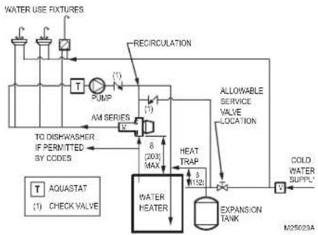
These AM-1 Series models can be installed in any position consistent with the intended use. For domestic hot water supply, the valve must be installed as shown in Fig. 1. There shall be no shut-off valves installed between the cold water line and the cold water connection on the AM-1 Series valve. Check valves shall be installed as indicated for NPT models; all AM-1 models with union fittings are supplied with integral check valves on both the hot and cold ports. A cold water service valve may be installed, as indicated, between the cold water supply line to the distribution system and the cold water line supplying both the water heater and the AM-1 Series valve.
flowchart
graph TD
    A["TO DISWASHER IF PERMITTED BY CODES"] --> B["PUMP"]
    B --> C["AM SERIES"]
    C --> D["RECIRCULATION"]
    D --> E["WATER HEATER"]
    E --> F["HEAT TRAP"]
    F --> G["COLD WATER SUPPLY*"]
    G --> H["EXPANSION TANK"]
    H --> I["ALLOWABLE SERVICE VALVE LOCATION"]
    I --> J["AQUASTAT (1) CHECK VALVE"]
    J --> K["T"]
    K --> L["1521"]
    L --> M["8 (203) MAX"]
    M --> N["8 (203) MAX"]
    N --> O["1521"]
    O --> P["1521"]
    P --> Q["M25020A"]
Fig. 1. AM-1 Series ASSE 1017 application. Dimensions shown in in (mm).
Installation of Union Sweat, CPVC, Union Propress, Push Connect and PEX Connections
— Union sweat connections, if used, should be soldered prior to assembly to the valve, or without the sealing gasket or optional check valve present. After the joint has cooled, the sealing gasket and/or check valves may be installed.
- CPVC fittings are limited to a system maximum temperature of 180^ (82°C) and 100 psi (689 kPa).
— PEX fitting and crimp ring (provided by Installer) are deigned to meet ASTM F1807 requirements.
- PEX tubing used with PEX fittings must meet ASTM F876 requirements.
- Press connections, use press tools and installation practices compatible with Viega systems.
— Push connect fittings can be used with both copper and LDPE (plastic). Utilize the included tube liners for non-copper applications.
Installation of Temperature Gauge Adapter
IMPORTANT
Union sweat connections must be soldered before the thermowell with O-ring and sealing gasket are installed. Install the thermowell with O-ring and sealing gasket after the joint has cooled.
- Install thermowell with O-ring to the thermometer adapter body.
- Tighten to 75 LB-IN ± 10 LB-IN. DO NOT OVER-TIGHTEN.
- Install the thermometer into the thermowell until seated and tighten the set screw to secure in place.
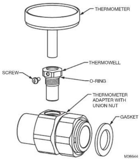
Fig. 2. Temperature gauge installation.
VALVE ADJUSTMENT
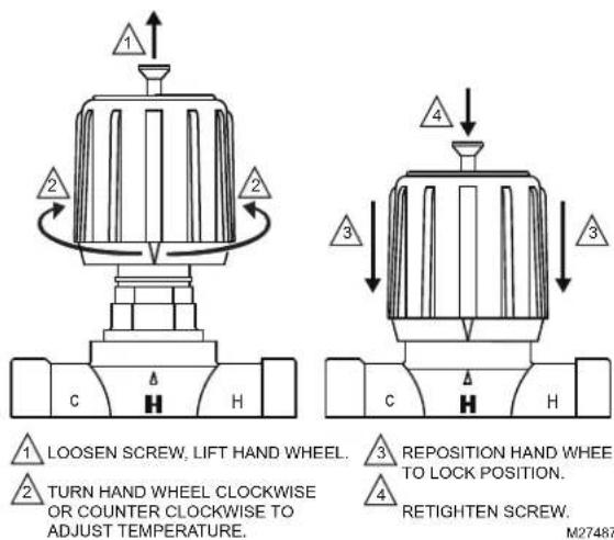
To adjust temperature setting of the mixing valve, attach thermostrip (supplied with the valve) to the piping connected to the Mix port of the valve. Loosen handwheel screw, lift handwheel and turn to desired temperature as indicated on the thermostrip. Reposition the hand wheel and retighten screw.
Temperature Setting Procedure
It is possible to limit the temperature range. To use this feature:
Thermostrip Installation
Clean pipe and firmly apply Thermostrip on mix outlet of valve. Flow water and adjust mixed outlet temperature for desired setting range. Actual mixed water temperature is indicated in green with 2^ F ( 1^ C) increments. Blue means slightly lower and brown means slightly higher.

WARNING
Water Temperature above 120°F (49°C) can cause serious injury. Mixing valve temperature setting should be done by licensed contractor per local code requirement. To ensure correct temperature control, use water thermometer at faucet outlet.
The thermostrip is ONE TIME USE ONLY for initial system temperature setting. Check expiration date printed on temperature strip to ensure temperature reading accuracy. If necessary, contact your Honeywell distributor to obtain a replacement thermostrip, part number TS205-064.
Thermostrip only included in models without the temperature gauge.
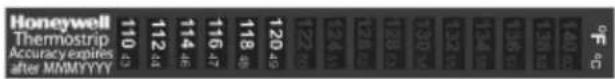
Fig. 3. Thermostrip.
Post Installation Procedure
- Write temperature setting on CAUTION label and sign in space provided.
- Attach CAUTION label to AM-1 valve.
- Explain CAUTION label to owner.
- Deposit this instruction sheet with owner.
OPERATION
The AM-1 series valve provides for automatic operation through the use of a thermostatic element in the product. The element will control the mixing of the hot and cold supply to provide mixed tempered water to connected fixtures. This provides constant water temperature under different working conditions.
MAINTENANCE PROCEDURES
Hard water conditions may result in scale deposits, causing binding of internal parts in extreme cases. Cleaning the internal parts will usually restore the valve to proper operating conditions. In some cases, it may be necessary to replace the lower assembly.
To clean and/or replace the lower assembly, shut off water and:
- With a screwdriver, remove screw and handwheel.
- Loosen upper nut (do not remove) to allow engaging an adjustable wrench on lower nut. Unscrew lower nut (counterclockwise). This removes top assembly.
-
Brass top assembly will pop up. Remove lower assembly, diffuser and spring.
-
Carefully remove any scaling (calcium deposit) or foreign particles from valve seat and other internal parts. Use vinegar to remove calcium. Soak parts until calcium becomes soft and can be scrubbed and washed off. Do not use solvents or scratch metallic / Teflon ^® coated surfaces.
-
Replace cleaned spring, diffuser and lower assembly following instructions below or use new replacement kit assembly. For correct kit number, see Table 1.
Install spring, diffuser and lower assembly:
A. Insert spring onto diffuser.
B. Insert diffuser with spring end first into body.
C. Fit valve top assembly into lower assembly and insert into valve.
D. Tighten lower nut.
E. Reposition handwheel and insert screw. Turn handwheel to desired temperature setting.
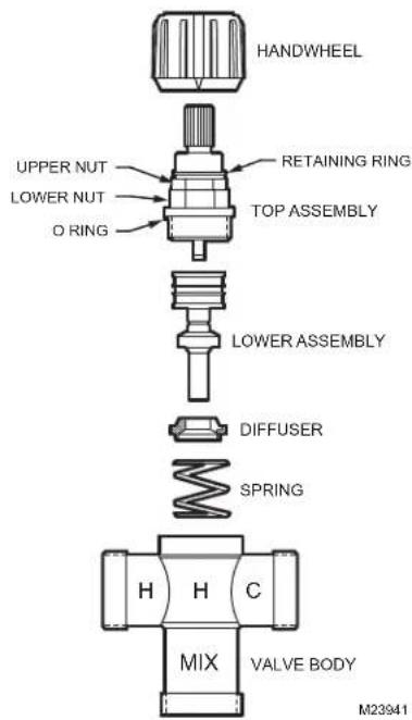
Fig. 4. AM-1 Series valves assembly.
Table 1. AM-1 Series Replacement Kits.
| Part No. Model Description | |
| AM-1-020RP C 70°-120°F (21°-49°C) ThermostaticElement Replacement Kit | |
| AM-1-025RP STD 70°-145°F (21°-63°C) ThermostaticElement Replacement Kit | |
| AM1-TG100-US-LF/U ALL 1/2" | AM1 Temp Gauge Tail PC w/Sweat |
| AM1-TG101-US-LF/U ALL 3/4" | AM1 Temp Gauge Tail PC w/Sweat |
| AM1-TG102-US-LF/U ALL 1" AM | M1 Temp Gauge Tail PC w/Sweat |
| TG200-UT/U ALL Thermometer, | 2" Dial w/ Threaded Well |
| TG250-UT/U ALL Thermometer, | 2.5" Dial w/ Threaded Well |
AM-1 Series ^™ is a trademark of Honeywell International, Inc.
ASSE ^® is a registered trademark of the American Society of Sanitary Engineering.
CSA ^* is a registered trademark of the Canadian Standards Association.
IAPMO ^5 is a registered trademark of the International Association of Plumbing and Mechanical Officials.
ASTM ^® is a registered trademark of the American Society for Testing and Materials.
Teflon ^* is a registered trademark of E.I. du Pont de Nemours and Company.
By using this Honeywell literature, you agree that Honeywell will have no liability for any damages arising out of your use or modification to, the literature. You will defend and indemnify Honeywell, its affiliates and subsidiaries, from and against any liability, cost, or damages, including attorneys' fees, arising out of, or resulting from, any modification to the literature by you.
Home and Building Technologies
In the U.S.:
Honeywell
715 Peachtree Street NE
Atlanta, GA 30308
customer.honeywell.com
* U.S. Registered Trademark
© 2018 Honeywell International Inc.
62-3075FFS-07 M.S. Rev. 08-18
Printed in United States
Honeywell
Honeywell
SÉRIE AM-1 ^MC
VANNES DE MÉLANGE ET DE RÉPARTITION THERMOSTATIQUES PROPORTIONNELLES STANDARD ET À PLAGE DE TEMPÉRATURES C – NPT, À SOUDER, FILETÉES, PVC-C, RACCORD-UNION PROPRESS, À COMPRESSION ET PEX
INSTRUCTIONS D'INSTALLATION
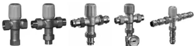
natural_image
Five different types of industrial pressure regulator fittings shown in grayscale, no text or symbols visibleHome and Building Technologies
Aux États-Unis :
Honeywell
715 Peachtree Street NE
Atlanta, GA 30308
customer.honeywell.com
Home and Building Technologies
En los EE. UU.:
Honeywell
715 Peachtree Street NE
Atlanta, GA 30308
customer.honeywell.com