KH 3106 ENERGY STATION PC 7 - Charging station TRONIC - Free user manual and instructions
Find the device manual for free KH 3106 ENERGY STATION PC 7 TRONIC in PDF.

User questions about KH 3106 ENERGY STATION PC 7 TRONIC
0 question about this device. Answer the ones you know or ask your own.
Ask a new question about this device
Download the instructions for your Charging station in PDF format for free! Find your manual KH 3106 ENERGY STATION PC 7 - TRONIC and take your electronic device back in hand. On this page are published all the documents necessary for the use of your device. KH 3106 ENERGY STATION PC 7 by TRONIC.
USER MANUAL KH 3106 ENERGY STATION PC 7 TRONIC
Operating and safety
instructions

Estação de energia
- Usage S. 45
- Technical data S. 45
- Charging S. 46
- Outputs for 1A S. 48
- Output for 10 A S. 50
- If it fails to work...? S. 51
- Screw connections S. 52
- Fuses S. 53
- Cleaning and care S. 54
0.Storage S.54 - Disposal S. 54
P
This product is intended
for the mobile power supply of low-voltage devices up to 10 A power consumption
- only for domestic use.
It is not intended:
- for use where a power failure could result in damage, e.g. medical equipment, aviation or space program etc.
not for use in commercial or industrial areas.
2. Technical data
Energy station
Rechargeable gel battery : 12V---/7Ah
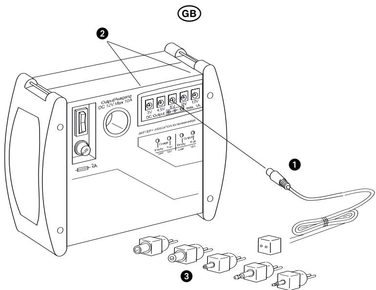
Low voltage jacks : 3V- /4,5V- /6V- (DC Output) 9V- /12V- unstabilised / 1 A
Motor vehicle socket : 12V----/10A
(DC 12V/max. 10 A)
Screw connections : 12 ~V = 1 / 10 ~A for max. 2 ~min .
Mains charging adapter
Power supply : 230V\~/50Hz
Charging output : 12V----/0,5A
Charging time : approximately 15 hours with empty battery
Protection class II
Safety instructions
To avoid danger from electric shock:
- Only use the device and its accessories in dry rooms, never in moist areas.
- If the mains charging adapter is not functional or damaged, do not continue using it under any circumstances. The mains charging adapter cannot be repaired – have it replaced by the service or specialist dealer.
To avoid fire hazards through electric short circuit:
- Carefully ensure that the screw connections can never be short circuited, e.g. through loose cables. For operational reasons these connections are not protected – this means that very high currents can flow (over 15 A).
- Never open the housing of the energy station.
- Only use the supplied connection cables. Others could possibly be not safe enough.
- Do not expose the energy station to any heat source whatsoever, e.g. sun radiation, heating...
- Do not allow children to play with the device without supervision.
Carefully keep these instructions for subsequent queries – and also hand them over to third parties together with the device!

3. Charging
Before using the device, satisfy yourself that the energy station, the connection cables and the mains charging adapter are in perfect condition.
Danger!
Never use a damaged connection cable. Short-circuit hazard!
a) Commissioning - initial charging!
The energy station is delivered with a low-level pre-charged battery. Prior to initial usage it must therefore be charged as described under b) or c).
Caution! The battery can lose considerable capacity should you use the energy station without fully charging it beforehand!
b) Charging via the power socket
The charging time for a completely discharged battery is approximately 15 hours:
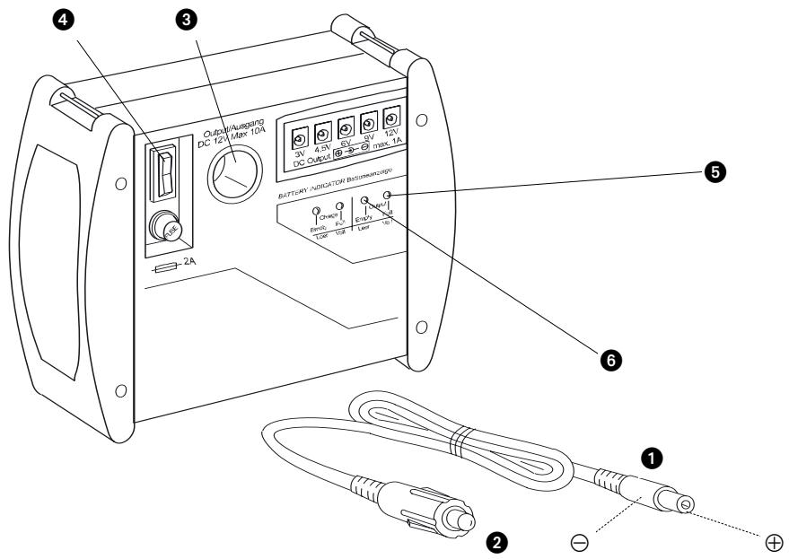
Insert the device plug of the mains charging adapter in the charging socket at the back of the device.
Insert the mains charging adapter in the socket.
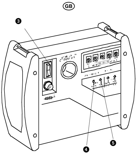
The energy station is charged by turning the main switch at the front to the "CHA" position.
While the energy station is charging, the red LED "Empty" will be illuminated.
When the battery is nearly charged, the green LED "Full" will start to be faintly illuminated. As soon as it is fully illuminated you can remove the mains charging adapter again.
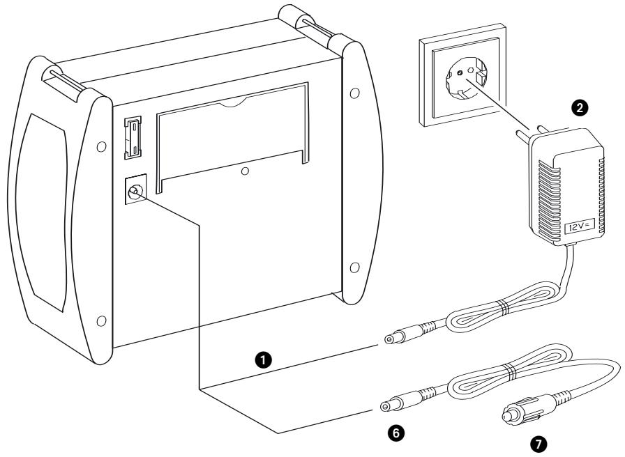
c) Charging via on-board voltage
You can also charge the energy station by way of the 12V on-board voltage system of a motor vehicle or sports boat:
6 First insert the device plug of the 12V on-board cable in the charging jack at the back of the device,
7 Then insert the cigarette lighter connector in the motor vehicle socket.
Danger!
This sequence is important as it prevents a short circuit during inadvertent contact of the device plug with the vehicle chassis.
Note: A charging process is only established if the charging voltage is higher than that of the battery. With a stationary vehicle this is frequently not the case. Generally speaking, charging is therefore only possible with the engine running.
4. Outputs for 1A
Caution! Before performing any kind of connection operations, always satisfy yourself that both your device as well as the energy station are switched off - that is the main switch in the "OFF" position (centre position). In this way you can prevent damage through connection faults.
a) Connecting device
A total of 5 connection jacks are available for the power supply of devices with a maximum power consumption of 1 A:
Insert the adapter cable...
in the connection jack, corresponding to the voltage required for your device.
3 Select the suitable connector for your device from the set.
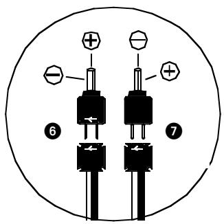
Caution! Before connecting your device to the energy station, first ensure that, "Positive" and "Negative" have not been switched. Otherwise your device can be damaged:
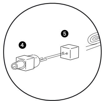
4 Connect the selected connector
5 ... and the receptacle so that positive and negative correspond to the marking on the jack of your device (Figure right).
GB
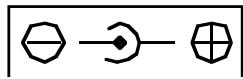
If the markings on the connector and the receptacle ...
are on the same side, positive on the connectors is at the top (inside) and negative at the bottom (outside).
are on opposite sides, positive on the connectors is at the bottom (outside) and negative at the top (inside).
Once you have connected your device to the energy station with the appropriate connectors ...
- you can set the main switch to "ON" - your device will now be supplied with power.
- A green LED "Full" is illuminated as soon as the main switch is switched on and sufficient energy is available.
- A red LED "Empty" is illuminated as soon as the main switch is switched on - but the battery is almost empty.
Caution! You must first recharge the battery if the red LED "Empty" is illuminated. Otherwise the battery will be depleted, usually resulting in a considerable loss of charging capacity.
Hint: Once you have established the correct connector assignment for your device, you can secure the connector with insulating tape to the receptacle so that you will immediately have a "suitable" cable for your device available the next time.
b) Removing the device
To discontinue supplying your device with power from the energy station, first ...
- switch off the device...
- and set the main switch on the energy station to "OFF" (centre position).
In this way you prevent that current is still flowing while the connector is being pulled. Sensitive devices sometimes malfunction as a consequence.
- Now you can pull the adapter cable connectors from both the device and the energy station.
c) If it fails to work...?
If none of the two LEDs light up after switching on, one of the fuses on the energy station might have blown. Changing the fuses is described in more detail in Chapter 8.
Should an LED light up on the energy station after switching on but your device fail to work, you should immediately switch off the energy station. In this case, initially check whether the cable is correctly connected – and “Positive” and “Negative” have not been switched. If required, also check the fuse in your device as described in its instructions.
GB
5. Output for 10 A
An output as motor vehicle socket is available for so-called "cigarette lighter connectors" for the power supply of devices to a maximum of 10 A.
These could be...
- cooler boxes
- car vacuum cleaners
- small portable TV sets etc. ...
Please consider that with a 10 A load the battery will be exhausted after not more than 45 minutes - depending on the charge condition, even much earlier.
Cooler boxes usually have a power consumption of 3 - 4 A per hour. With a battery capacity of 7 Ah, this corresponds to just under 2 hours of operating time. You can roughly estimate the operating time for your device using this calculation example.
Caution! Before performing any kind of connection operations, always satisfy yourself that both your device as well as the energy station are switched off that is the main switch in the "OFF" position (centre position).
In this way you can prevent damages through connection faults.
GB
a) Connecting the device
Caution! Before connecting your device to the energy station, you must first ensure that "Positive" and "Negative" are not switched. Otherwise your device could be damaged
1 With the supplied cable the device connector is connected so that Positive is on the inside and Negative on the outside, as shown. You can
- use this cable if the jack on your device is marked thus:
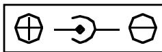
- not use this cable if the jack on your device is marked thus:
On devices with permanently connected cable with motor vehicle connector, "Positive" and "Negative" have the correct polarity.
Insert the device connector of the supplied cable in the jack on your device.
Insert the motor vehicle connector
3 ... in the motor vehicle socket on the energy station.
Once you have connected your device to the energy station ...
you can now set the main switch to "ON" - your device will now be supplied with power
A green LED "Full" will be illuminated as soon as the main switch is switched on and sufficient energy is available.
A red LED "Empty" will be illuminated as soon as the main switch is switched on – but the battery is almost empty.
Caution!. You will first have to recharge the battery if the red LED "Empty" is illuminated. Otherwise the battery will be depleted, usually resulting in a considerable loss of charging capacity.
b) Removing the device
If you wish to terminate the power supply for your device from the energy station, you should first ...
- switch off the device ...
and also set the main switch on the energy station to "OFF" (centre position).
In this way you will prevent that current is still flowing while the plug is being pulled. Sensitive devices may malfunction as a consequence.
- You can now pull the connectors from both the device and the energy station.
6. If it fails to work...?
If none of the two LEDs light up after switching on, one of the fuses on the energy station might have blown. Changing the fuses is described in more detail in Chapter 8.
Should an LED light up on the energy station after switching on but your device fail to work, you should immediately switch off the energy station. In this case, initially check whether the cable is correctly connected – and “Positive” and “Negative” have not been switched. If required, also check the fuse in your device as described in its instructions.

7. Screw connections
These are intended for use of 12V devices requiring a high starting current for switching on, but which do not otherwise consume more than 10 A per hour.
Devices with a high starting current could be for instance ...
- 12V vacuum cleaners
- 12V drilling machines
- 12V television sets etc.
Although these may not require more than 10 A in operation, the fuse will immediately trip when switched on. In this case such devices cannot be operated on the 10 A protected motor vehicle socket - but only by way of the screw terminals described here.
a) Screw or plug connection?
The screw terminals are hollow to accommodate so-called "banana plugs". If such are provided on your device cable you can insert these in the screw terminals from the top instead of screw-connecting!
Danger!
Extremely high current flows are possible here that are even capable of heating thick cables red hot!
However these high currents are required for the starting of some devices. The screw connections are therefore...
not routed by way of a fuse and
not by way of the main switch... - voltage is present continuously!
For this reason it is imperative to ensure that no short-circuit is created on the screw terminals under any circumstances!
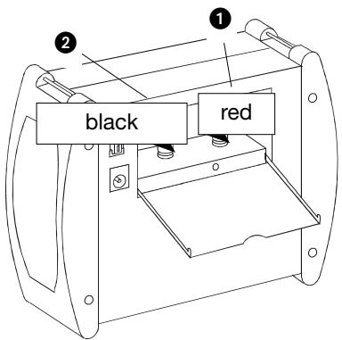
b) Devices with fixed cable
If the cable is permanently connected with the device you can simply ...
connect the "Positive" core (usually red) to the red screw terminal
2 and the „Negative“ core (usually black or blue) to the black screw terminal.
To do so, turn the plastic cap on the screw terminals loose, clamping the bright cores below when retightening.
c) Devices with loose cable
If the cable is not permanently connected to the device but has a bright device plug ...
- first insert the device plug in the jack on the device before c onnecting the cores to the screw terminals.
With this sequence you prevent short-circuit hazards should the bright connector inadvertently come in contact with metallically conductive objects during the connecting work.
GB
8. Fuses
If none of the LED is illuminated after switching on, one of the two fuses might have blown- either
- the flat fuse at the back or
- the round fuse at the front.
If an LED is illuminated after switching on but no current is flowing via the cigarette lighter cable regardless, ...
- the cable fuse in the cigarette lighter connector might have blown.
Danger!
First set the main switch to "OFF" and pull all cables from the energy station before changing any fuses.
In this way you will prevent that the new fuse will burn in your fingers if the fault persists - risk of injury!
Danger!
Fuses are important protective devices to prevent damage. Never render them ineffective but ...
- always replace fuses with fuses of the same rating, never "higher" ratings.
- never bypass fuses, this could result in fires.
a) Changing round fuse:
- Unscrew the cap at the front of the round fuse and fit a new "2 A (T2A 250V)" fuse.
b) Changing flat fuse:
Pull out the flat fuse at the back of your device (e.g. long-nose pliers) and insert a new "10 A (C10)" fuse.
c) Changing cable fuse:
4 Unscrew the cable fuse cap on the motor vehicle connector and insert a new "1 A (T1A 250 V)" fuse.
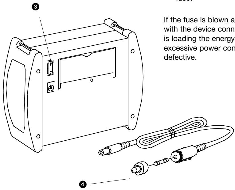
If the fuse is blown again immediately with the device connected, your device is loading the energy station with excessive power consumption – or it is defective.

9. Cleaning and care
Danger!
Never open the device housing.
There are no controls inside. The opened housing can pose a fire hazard through short-circuit currents.
Before cleaning the device....
- first switch the main switch to the "OFF" position...
- and pull all cable connections between energy station and any connected devices.
- If you wish to clean the mains charging adapter, pull it from the socket and from the charging jack as well.
Danger!
- On no account must the device components be immersed in water or other liquids! This can severely damage the energy station – and there is even the danger of electric shock on the mains charging adapter.
- All surfaces and cables are best cleaned with a slightly moistened washing-up cloth. Always dry the device before reuse.
- Do not use any detergent or solvent. These can damage the device especially the print.
10. Storage
Because of the natural self-discharge of batteries the energy station should be fully charged once more before putting it away for several days or weeks.
If you wish to store the device for an extended period of time without usage, it should be recharged before the expiry of 6 months to prevent depletion of the battery.
- First switch the main switch to the "OFF" position...
- and pull all cable connections between energy station and any connected devices.
- Stow the cables and connectors in the lateral compartments on the device ...
and finally close all lids. - Store the device in a dry place.
11. Disposal
A lead gel battery is installed in the energy station that must not be disposed of by way of domestic waste.
- For this reason, return the energy station to a disposal collection point established for this purpose.
The remaining device parts do not contain any materials subject to any special disposal regulations at the time the instructions were compiled (August 2003). If required, ask your community authority if the legal situation has changed in the meantime.

Estação de energia
Tronic KH 3106
1. Finalidade de uso
c) Laden via boardspanning
(DC Output) 9V = /12V =
σαθεροποιμενα /1A
Ppiz
autokivntou: 12V- /10A
(DC 12V/max. 10 A)
Biodtoi ouv8oai: 12V=/10A yia 2
Avtanttopas
φόPTiOng δIKTuOu
IoXu pεμaToC: 230V\~/50Hz
E\xo0o0c 分 12V=0,5A
Statement of conformity
D-44867 Bochum, Germany, hereby declare that this pro
duct conforms with the following EC regulations:
EC low voltage regulations 73/23/EWG:
EN 60335-1
EN 61558-1
EN 61558-2-6
Electromagnetic compatibility 89/336/EWG:
EN 55014-1
EN 55014-2
EN 61000-3-2
EN 61000-3-3
Type: KH 3106 BFP DK

Bochum, 04.11.2003
Hans Kompernaß
- Managing Director -
D
In case your apparat fails to function as expected, it must be given for repairs to a service centre authorised by the manufacturer or a qualified technician. For this purpose, please contact our customer service. The address is given in the enclosed warranty card.