
EY-3D-EMT1 - Remote control MITSUBISHI - Free user manual and instructions
Find the device manual for free EY-3D-EMT1 MITSUBISHI in PDF.
| Product type | Infrared emitter for 3D glasses |
| Brand | MITSUBISHI |
| Model | EY-3D-EMT1 |
| Dimensions (W x H x D) | 110 x 33 x 49 mm |
| Weight | 50 g |
| Power supply | Via projector through mini DIN 5-pin cable |
| Main function | Transmission of infrared signals to 3D glasses for 3D viewing |
| Compatible projectors | Mitsubishi projectors supporting 3D images (models HC9000D/HC9000DW, etc.) |
| Vertical transmission angle | Adjustable by 5 degrees |
| Transmission range | Side view and top view (illustration in the manual) |
| Package contents | 3D emitter, double-sided adhesive tape, user manual |
| Connection | 3D EMITTER terminal on the projector via mini DIN 5-pin cable (1 m or 15 m) |
| Safety | Do not use if smoke, noise, or odor occurs; do not drop or modify |
| Maintenance | Clean with a soft, dry cloth; avoid solvents |
| Usage conditions | Avoid proximity to other infrared devices (remote controls, heaters) |
| Compliance | EU Directives 2004/108/EC and 2006/95/EC; FCC Class B; Canada NMB-003 |
| Repairability | Contact the distributor in case of malfunction; no user-serviceable parts |
| Environmental information | Do not dispose with household waste; recycle via selective collection |
Frequently Asked Questions - EY-3D-EMT1 MITSUBISHI
User questions about EY-3D-EMT1 MITSUBISHI
0 question about this device. Answer the ones you know or ask your own.
Ask a new question about this device
Download the instructions for your Remote control in PDF format for free! Find your manual EY-3D-EMT1 - MITSUBISHI and take your electronic device back in hand. On this page are published all the documents necessary for the use of your device. EY-3D-EMT1 by MITSUBISHI.
USER MANUAL EY-3D-EMT1 MITSUBISHI
What's included in the box........5
Overview. 5
Installation and connection .6
Troubleshooting. 9
Specifications. 9
Mitsubishi projectors supporting 3D images* (as of November 2010)
HC9000D/HC9000DW
Supported projectors are subject to change without notice.
- Mitsubishi DLP™ Link projectors supporting 3D images are excluded.
For details about the 3D system, see the descriptions of the 3D in the User Manual supplied with the projector.
WARNING:
Contact your dealer if there is something wrong with your 3D Emitter.
Do not operate if smoke, strange noise or odor comes out of your projector. It might cause fire or electric shock. In this case, contact your dealer immediately.
Do not keep using the damaged 3D Emitter.
It can lead to fire or electric shock.
Do not drop or modify your 3D Emitter.
It can lead to breakdown or other failure.
CAUTION:
Not for use in a computer room as defined in the Standard for the Protection of Electronic Computer/Data Processing Equipment, ANSI/NFPA 75.
Using precautions
This 3D Emitter is used only for Mitsubishi projectors supporting 3D images.
Use this 3D Emitter only for viewing 3D images on the supported Mitsubishi projectors.
The 3D Glasses work by receiving an infra-red light from the 3D Emitter. Other infra-red communication devices, lighting fixtures, or heating appliances placed near the 3D Emitter may affect the operation of the 3D Glasses.
View 3D images within the specified signal reception range. (See the illustration of "Transmission range of the infra-red signal.")
The signal of the 3D Emitter may be affected by that of the infra-red remote control. In such a case, change the orientation of the 3D Emitter.
A remote control may operate improperly while you watch the 3D images, however, it is not a malfunction.
When using the device in Europe: COMPLIANCE NOTICE
This device complies with the requirements of the EC Directive 2004/108/EC "EMC Directive" and 2006/95/EC "Low Voltage Directive".
The electro-magnetic susceptibility has been chosen at a level that gains proper operation in residential areas, on business and light industrial premises and on small-scale enterprises, inside as well as outside of the buildings.
COMPLIANCE NOTICE OF FCC
This equipment has been tested and found to comply with the limits for a Class B digital device, pursuant to Part 15 of the FCC Rules. These limits are designed to provide reasonable protection against harmful interference in a residential installation. This equipment generates, uses and can radiate radio frequency energy and, if not installed and used in accordance with the instructions, may cause harmful interference to radio communications. However, there is no guarantee that interference will not occur in a particular installation. If this equipment does cause harmful interference to radio or television reception, which can be determined by turning the equipment off and on, the user is encouraged to try to correct the interference by one or more of the following measures:
- Reorient or relocate the receiving antenna.
- Increase the separation between the equipment and receiver.
- Connect the equipment into an outlet on a circuit different from that to which the receiver is connected.
- Consult the dealer or an experienced Radio/TV technician for help.
Changes or modifications not expressly approved by Mitsubishi could void the user's authority to operate this equipment.
COMPLIANCE NOTICE OF INDUSTRY CANADA
This Class B digital apparatus complies with Canadian ICES-003.
Declaration of Conformity
Model number: EY-3D-EMT1
Trade name: MITSUBISHI ELECTRIC
Responsible party: Mitsubishi Digital Electronics America, Inc.
9351 Jeronimo Road, Irvine, CA 92618 U.S.A
Telephone number: +1-(949) 465-6000
This device complies with Part 15 of the FCC Rules. Operation is subject to the following two conditions:
(1) this device may not cause harmful interference, and
(2) this device must accept any interference received, including interference that may cause undesired operation.

Note: This symbol mark is for EU countries only.
This symbol mark is according to the directive 2002/96/EC Article 10 Information for users and Annex IV, and/or to the directive 2006/66/EC Article 20 Information for end-users and Annex II.
Your MITSUBISHI ELECTRIC product is designed and manufactured with high quality materials and components which can be recycled and/or reused.
This symbol means that electrical and electronic equipment, batteries and accumulators, at their end-of-life, should be disposed of separately from your household waste.
If a chemical symbol is printed beneath the symbol shown above, this chemical symbol means that the battery or accumulator contains a heavy metal at a certain concentration. This will be indicated as follows:
Hg: mercury (0,0005%), Cd: cadmium (0,002%), Pb: lead (0,004%)
In the European Union there are separate collection systems for used electrical and electronic products, batteries and accumulators.
Please, dispose of this equipment, batteries and accumulators correctly at your local community waste collection/recycling centre.
Please, help us to conserve the environment we live in!
Information on Disposal in other Countries outside the European Union
This symbol mark is only valid in the European Union. If you wish to discard this product, please contact your local authorities or dealer and ask for the correct method of disposal.
Environment care information for users in China

This symbol mark is only valid in China.
Using this 3D Emitter and the separately sold 3D Glasses (EY-3DGS-1U), you can enjoy viewing 3D images on Mitsubishi projectors supporting 3D images. For viewing 3D images or making the related settings, see the User Manual supplied with the projector.
What's included in the box
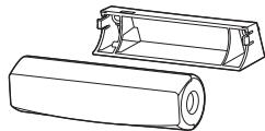
3D Emitter
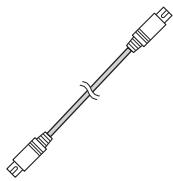
Mini DIN 5-pin cable (1 m)
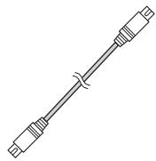
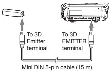
Mini DIN 5-pin cable (15 m)

Screws (2)

Double-faced tape
User Manual
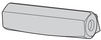
Overview
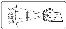
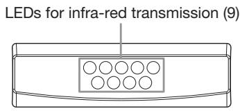
Infra-red transmission part
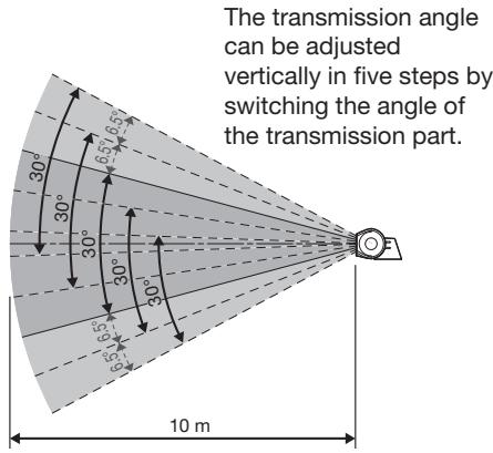
This part transmits the infra-red signals. The transmission angle can be adjusted vertically in five steps.
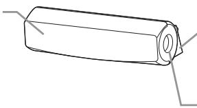
Base part
3D Emitter terminal
Connect this terminal to the 3D EMITTER terminal on the projector using the supplied mini DIN 5-pin cable.
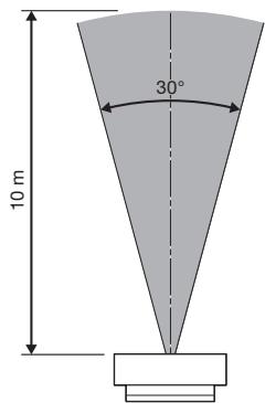
Transmission range of the infra-red signal
This 3D Emitter transmits the infra-red signal in the range illustrated below.
View from the side
View from the top
The above figures are approximate and may be slightly different from the actual measurements.
Place the 3D Emitter so that you can use the 3D Glasses within the transmission range described above.
Normally, attach the 3D Emitter to the projector as described on page 7.
However, if the 3D Glasses don't receive the signal properly when you attach the 3D Emitter to the projector, place the 3D Emitter according to the procedure described on page 8.
- Do not put any object which obstructs the communication between the 3D Emitter and the 3D Glasses.
- Do not place the 3D Emitter near the remote control sensor of other devices.
- The transmission distance is decreased when the infra-red signal from the 3D Emitter is transmitted to the 3D Glasses by reflecting on the screen. In addition, the transmission distance in such case varies depending on the characteristics of the screen.
Attaching the 3D Emitter to the projector
Preparation:
Turn off the power of the projector.
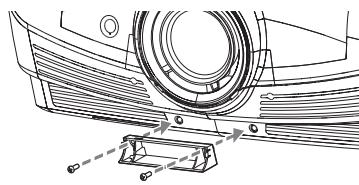
- Remove the caps covering the 3D Emitter attaching part on the projector.
- Secure the base part of the 3D Emitter to the 3D Emitter attaching part on the projector using the supplied screws.
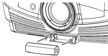
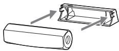
- Put the infra-red transmission part of the 3D Emitter into the base part.
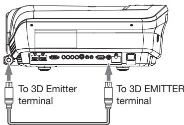
- Connect the 3D Emitter terminal on the 3D Emitter to the 3D EMITTER terminal on the projector using the supplied mini DIN 5-pin cable (1 m).
-
Turn on the power of the projector and make settings for viewing 3D images.
-
For details, see the User Manual supplied with the projector.
-
Prepare the 3D Glasses.
- Adjust the vertical angle of the 3D Emitter so that the 3D Glasses can receive the infra-red signal.

Mini DIN 5-pin cable (1 m)
Placing the 3D Emitter in an arbitrary place
Preparation:
Turn off the power of the projector.
- Put the infra-red transmission part of the 3D Emitter into the base part.
- Secure temporarily the 3D Emitter in an arbitrary place (such as the wall around the screen).
-
Connect the 3D Emitter terminal on the 3D Emitter to the 3D EMITTER terminal on the projector using the supplied mini DIN 5-pin cable (15 m).
-
Turn on the power of the projector and make settings for viewing 3D images.
- For details, see the User Manual supplied with the projector.
- Prepare the 3D Glasses.
- Adjust the position and angle of the 3D Emitter so that the 3D Glasses can receive the infra-red signal.
After completing the adjustment, fix the 3D Emitter firmly using the supplied double-sided tape, etc.
Before asking for repair of the 3D Emitter, check the following.
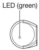
- When you change the mode of the projector to the 3D mode, check that the LED (green) on the 3D Emitter is illuminated.
- See the front of the 3D Emitter through a digital camera or a cell phone camera and check that the LEDs for infra-red transmission (9) are illuminated.
See the User Manual supplied with the projector.
Specifications
The specifications and outside appearance are subject to change without prior notice.
| Model | EY-3D-EMT1 |
| Dimensions (W x H x D) | 110 x 33 x 49 mm |
| Weight | 50 g |
EMETTEUR 3D
MODELE
EY-3D-EMT1
Manuel utiliseur
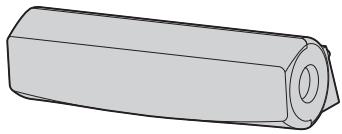
Table des matieres
(Stand: November 2010)
HC9000D/HC9000DW
CONFORMITA INDUSTRY CANADA
Note: This symbol mark is for China only.
PykoBoDCTBO NOIb3OBaTeJIa
Copepkxhanie
TexHnka 6e3oNaChOCTn. 2
Cm.PykoOIOCTBOIOnb3OBaTeJIa,NoctabJIaMeMOrOcPpoEeTOpOM.
XapakTepnctnkn
Cneunkaunn n BheHnBn DmOry 6bTb N3MeHebI 6e npedBaPntelhOro onOBeueHn.
Electronic Computer/Data Processing
Equipment, ANSI/NFPA 75の報告を適用表現予函申請者は合同の承認書に相応。
在
OPMERKING AANGAANDE OVEREENSTEMMING MET FCC
OPMERKING AANGAANDE OVEREENSTEMMING MET INDUSTRY CANADA
Effective only in Japan.
- WARNING:
- CAUTION:
- Using precautions
- When using the device in Europe: COMPLIANCE NOTICE
- COMPLIANCE NOTICE OF FCC
- COMPLIANCE NOTICE OF INDUSTRY CANADA
- Declaration of Conformity
- Information on Disposal in other Countries outside the European Union
- Environment care information for users in China
- What's included in the box
- Overview
- Infra-red transmission part
- Base part
- 3D Emitter terminal
- Transmission range of the infra-red signal
- View from the side
- View from the top
- Attaching the 3D Emitter to the projector
- Preparation:
- Placing the 3D Emitter in an arbitrary place
- Specifications
- EY-3D-EMT1
- Table des matieres
- HC9000D/HC9000DW
- CONFORMITA INDUSTRY CANADA
- PykoBoDCTBO NOIb3OBaTeJIa
- Copepkxhanie
- XapakTepnctnkn
- 在
- OPMERKING AANGAANDE OVEREENSTEMMING MET FCC
- OPMERKING AANGAANDE OVEREENSTEMMING MET INDUSTRY CANADA
Brand : MITSUBISHI
Model : EY-3D-EMT1
Category : Remote control