X52 FLIGHT CONTROL SYSTEM - Joysticks and flight controllers SAITEK - Free user manual and instructions
Find the device manual for free X52 FLIGHT CONTROL SYSTEM SAITEK in PDF.
| Product Type | Joystick and throttle for flight simulator |
| Brand | SAITEK |
| Model | X52 Flight Control System |
| Dimensions (estimated) | 300 x 200 x 150 mm (joystick + throttle) |
| Weight (estimated) | Approximately 1.5 kg |
| Power Supply | USB 5V, 500mA (USB cable included) |
| Number of programmable buttons | 19 buttons + 2 multidirectional hats with 8 positions + 3 toggle switches + scroll wheel + 2-stage trigger |
| Analog Axes | X, Y, Twist (rudder), throttle, 2 rotary knobs, linear slider |
| Multi-function display (MFD) | Backlit screen displaying mode, profile, clock, stopwatch, button names |
| Backlighting | Adjustable LEDs on keys and MFD, control via Windows control panel |
| Mode selector | 3-position rotary switch (up to 6 modes with Pinkie key) |
| Pinkie key | Metal, Shift function to double programmable commands |
| Rudder lock | RLOCK switch on the base to disable Twist rotation |
| Materials | Metal parts (trigger, Pinkie key) for durability |
| Compatibility | Windows (drivers included), DirectX 8.1 or higher |
| Box contents | Joystick, throttle, driver CD, user manual |
| Maintenance and cleaning | Clean with a dry, soft cloth. Do not use liquids or solvents. |
| Safety | Use only USB power. Do not expose to moisture or extreme temperatures. |
| Spare parts and repairability | Contact SAITEK technical support for any parts or repairs. |
| General information | Designed for flight simulators, programmable via SST software for advanced customization. |
Frequently Asked Questions - X52 FLIGHT CONTROL SYSTEM SAITEK
User questions about X52 FLIGHT CONTROL SYSTEM SAITEK
0 question about this device. Answer the ones you know or ask your own.
Ask a new question about this device
Download the instructions for your Joysticks and flight controllers in PDF format for free! Find your manual X52 FLIGHT CONTROL SYSTEM - SAITEK and take your electronic device back in hand. On this page are published all the documents necessary for the use of your device. X52 FLIGHT CONTROL SYSTEM by SAITEK.
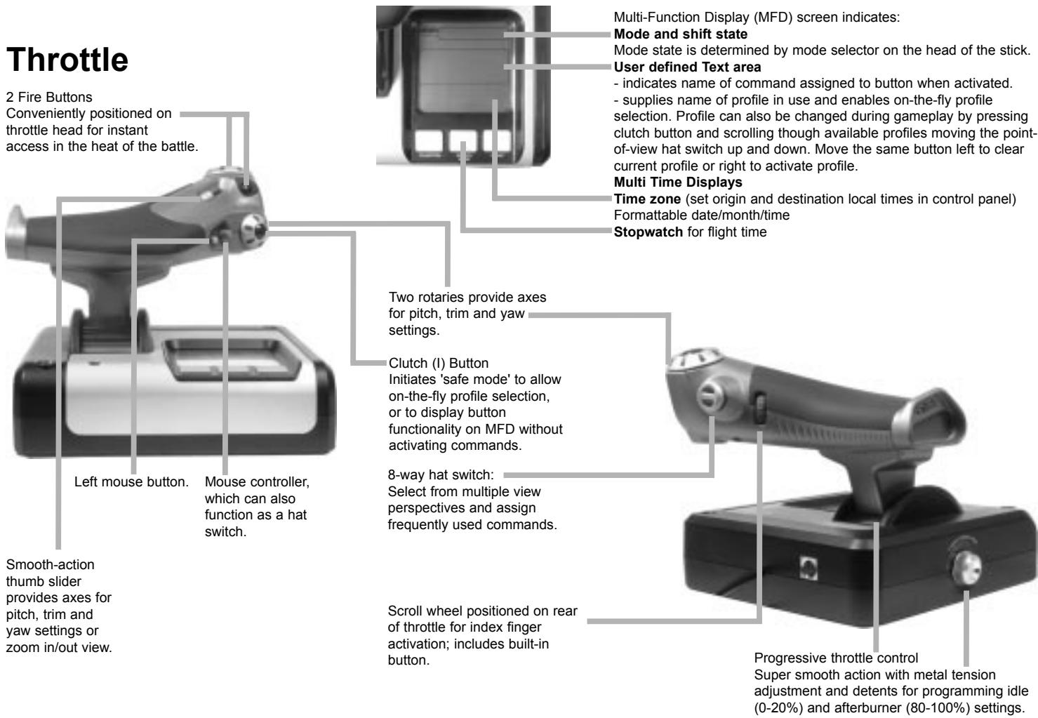
USER MANUAL X52 FLIGHT CONTROL SYSTEM SAITEK
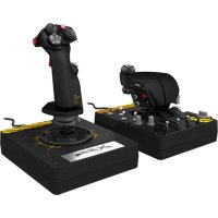
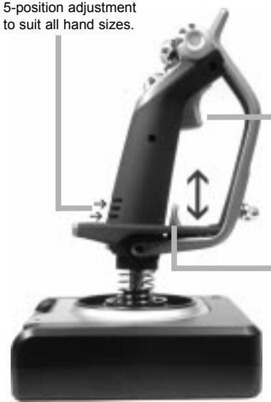
5-position adjustment to suit all hand sizes.
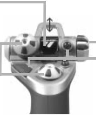
2-Stage metal trigger
Destroy the enemy with the aid of a precise and durable, cool-touch trigger. Two-stages can be programmed with separate fire functions.
3 toggle switches
Spring loaded and conveniently positioned on the base for an extra 6 programmable flight commands.
Cool-touch metal pinkie switch can be assigned shift functionality t double up on programmabl commands.
3D Rudder Twist handle on joystick for precise rudder control; includes integrated rudder lock mechanism.
Precision centering mechanism Non-contact technology on x and y axes and constant spring force reduce free play, improve control and increase durability.
Missile Launcher
Flip up the spring-loaded safety cover to activate missile launches.
2x8-way hat switches -1 pre-defined as point of view;select from multiple view perspectives and assign frequently used commands.
Mode selector switch 3-position rotary switch with tri-state LED to indicate program mode.
3 Fire Buttons Backlit buttons conveniently positioned on joystick head for instant access in the heat of the battle.
General Features
Backlighting
Illuminated buttons and Multi-Function Display (MFD) - ideal for low light environments, guaranteed to stand out from the crowd. Adjust brightness via Windows control panel.
Metal parts
Part metal construction for increased durability and maximum comfort during extended gameplay.
GETTING STARTED
In order for this product to function correctly please install the drivers on the CD supplied with this product.
INSTALLATION FOR USERS OF WINDOWS® XP
A) Drivers Only For Typical Users
1 With your computer switched on, close down any programs that are currently running and insert the Saitek Smart Technology CD into your CD-ROM drive.
2 When the Introduction Screen appears, click Install Software to continue. If the CD does not run automatically, select Start from the Windows® Taskbar, then Run and type D:\Setup.exe and click OK - where D:\ is the letter of your CD-ROM drive.
3 When the Welcome screen appears, click Next to continue.
4 After reading the Disclaimer, select the I accept the terms of the Disclaimer option and click Next to continue.
5 At the Driver Setup screen, if you haven't already done so, plug in your controller and click on Next.
6 At the Driver Setup screen, click Next to test your controller.
7 When the Saitek Controller screen appears, try out all your controller's buttons and controls to show that it is working properly. When you have finished, click OK. For more information on the use of the control panel, please see the Maintaining your Controller Settings section of this manual.
8 At the Software Setup screen, select Do not install the SST Programming Software and click Next. The Programming Software can be installed at a later date by following instruction (B). below
9 At the Registration screen, select Check this box to register now and follow the on-screen instructions, or you can choose to select this option later.
10 Click on Finish to complete the installation.
B) Drivers and Programming Software For Advanced Users
1 Follow points 1 - 7 of the install procedure in A), then at the Software Setup screen, select Install the SST Programming Software and click Next.
2 In the following Software Setup screen, click Next and follow the on-screen instructions. At this point you will be asked to install such features as the Saitek Magic Mouse, HID-compliant mouse, Saitek Magic Keyboard and HID Keyboard Device (these are what XP calls the various elements of your Saitek controller). Continue to click on Next and Finish to accept the installation until the Registration screen appears.
3 At the Registration screen, select Check this box to register now and follow the on-screen instructions, or do not select this option and register later.
4 Upon completion of the installation, you have the option to Run Profile Editor, which will give you a view of the 3D programming environment. If you do not wish to see the Profile Editor at this point, just uncheck the box and click on Finish to complete the installation.
INSTALLATION FOR USERS OF WINDOWS® 2000
A) Drivers Only For Typical Users
1 With your computer switched on, close down any programs that are currently running and insert the Saitek Smart Technology CD into your CD-ROM drive.
2 When the Introduction Screen appears, click Install Software to continue. If the CD does not run automatically, select Start from the Windows® Taskbar, then Run and type D:\Setup.exe and click OK - where D:\ is letter of your CD-ROM drive.
3 When the Welcome screen appears, click Next to continue.
4 After reading the Disclaimer, select the I accept the terms of the Disclaimer option and click Next to continue.
5 At the Device Driver Installation screen, click on Next and follow the on-screen instructions.
6 When prompted, plug your controller's USB connector into your computer, then click on Configure.
7 When the Controller Properties screen appears, click Next to view the Test screen.
8 Now try out all your controller's buttons and controls to show that it is working properly. When you have finished, click OK.
9 At the Programming Software screen, select Typical User and click Next.
10 At the Registration screen, select Register and follow the on-screen instructions or select Register Later and click Next.
11 Click on Finish to complete the installation.
B) Drivers and Programming Software For Advanced Users
1 Follow points 1 - 8 of the install procedure in A), then at the Programming Software screen, select Advanced User and click Next.
2 At the Programmable Controller Drivers screen, click Update and follow the on-screen instructions.
3 Then at the Installation of programming software successful screen, click Next.
4 At the Registration screen, select Register and follow the on-screen instructions or select Register Later and click Next.
5 Upon completion of the installation, you have the option to Run Profile Editor, which will give you a view of the 3D programming environment. If you do not wish to see the Profile Editor at this point, just uncheck the box and click on Finish to complete the installation.
INSTALLATION FOR USERS OF WINDOWS® 98 AND ME
A) Drivers Only For Typical Users
1 With your computer switched on, close down any programs that are currently running and insert the Saitek Smart Technology CD into your CD-ROM drive.
2 When the Introduction Screen appears, click Install Software to continue. If the CD does not run automatically, select Start from the Windows® Taskbar, then Run and type D:\Setup.exe (where D: is your CD drive) and click OK.
3 When the Welcome screen appears, click Next to continue.
4 After reading and accepting the Disclaimer, click Next to continue.
Note: For your controller to work, you must have a minimum of Microsoft® DirectX® 8.1 installed on your computer. The
installer will automatically recognize if this software needs to be added, and will allow you to install it directly from the Saitek Product Companion CD, if necessary.
If you are asked to install Microsoft DirectX® 8.1, click Install and follow the on-screen instructions, and then restart your computer when prompted. Make sure that you leave the Saitek CD in the drive when restarting. After this software has been installed, you will automatically be taken to the installation to continue with the next step.
5 Follow the on-screen instructions and select Yes, I want to restart my computer now when prompted.
6 After the restart, at the Device Driver Installation screen, click on Next and follow the on-screen instructions.
7 When prompted, plug your USB connector into your computer.
8 When the Controller Properties screen appears, click Next to view the Test Screen.
9 Now try out all your controller buttons and controls to show that it is working properly. When you have finished, click OK.
10 At the Programming Software screen, select Typical User and click Next.
11 At the Registration screen, select Register my Saitek controller online, click Next and follow the on-screen instructions or select Register Later and click Next.
12 Click on Finish to complete the installation.
B) Drivers and Programming Software For Advanced Users
1 Follow points 1 - 9 of the install procedure in A), then at the Programming Software screen, select Advanced User and click Next.
2 At the Programmable Controller Drivers screen, click Update and follow the on-screen instructions. At this point you will be asked to insert your Windows® CD, however, DO NOT do this, just click on OK. At the next screen, type C:\windows\system into the prompt and click OK and follow the on-screen instructions.
3 At the Installation of programming software successful screen, click Next.
4 At the Registration screen, select Register my Saitek controller online, click Next and follow the on-screen instructions or select Register Later and click Next.
5 Upon completion of the installation, you have the option to Run Profile Editor, which will give you a view of the 3D programming environment. If you do not wish to see the Profile Editor at this point, just uncheck the box and click on Finish to complete the installation.
MAINTAINING YOUR CONTROLLER SETTINGS
Your Saitek X52 Flight Control System (FCS) is supplied ready for use. However, we want you to use it in the way that suits you best. We've therefore included the facility for you to change various settings on your stick and throttle units. You can, for example, vary the brightness of the LED buttons, check your stick is working correctly or change the way the date is displayed on your Multi-Functional Display (MFD).
You change your controller settings in the Saitek X52 Flight Stick properties window. There are two ways you can open this window. Either:
- Double-click on the Game Controllers icon in the Control Panel and then click Properties in the Game Controllers window that is displayed. Or,
- If the SST programming software has been installed, right-click on the Saitek X52 Flight Stick profiler icon in your task bar and select Control Panel from the popup list of options displayed.
The Saitek X52 Flight Stick properties window consists of five separate tabs. You can view and change various controller settings in each tab. The settings you can change are described in the following sections.
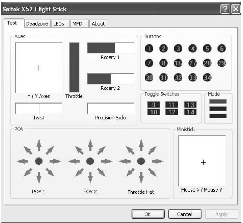
Testing your controller
You can make sure that the various features of your controller are working correctly. You do this in the Test tab of the Saitek X52 Flight Stick properties window.
To test your controllers, follow the steps below:
1 Click the Test tab.
The controller features that you can test are displayed below.
2 Test each feature as required.
The way you do this varies, depending on what the feature does. It may, for example, involve pressing the corresponding button, or turning the corresponding rotary control.
The features you can test are explained in the following sections.
Testing axes
You can test the following axes and controls:
| Feature | Explanation |
| X/Y Axes | Move the flight stick backwards and forwards or from left to right. The + symbol moves in the X/Y Axes box, to show the drivers are picking up the stick movement correctly. |
| Twist | The vertical gray line represents the center point of the flight stick. Rotate the flight stick clockwise or anti-clockwise. This is the rudder that enables you to change direction outside the X and Y axes. If the drivers are detecting the movement correctly a red band is displayed on either side of the center point line. |
| Throttle | Move the throttle up or down to increase or decrease your acceleration. A red band shows the current rate of acceleration, ranging from 0% (no red) to the maximum acceleration at 100% (the box is filled with red). |
| Rotary 1 and 2 | Rotate the rotary controls on the throttle unit. These are user-defined via the SST programming software or within each game. They range from 0% (no red) to 100% (the box is filled with red). You may, for example, use them to control fuel mixture or radar gain. |
| Precision Slide | Move the slide control on the throttle unit. This is user-defined via the SST programming software or within each game, and ranges from 0% (no red) to 100% (the box is filled with red). You may, for example, use it to control pitch or fuel mixture. |
Testing buttons, toggle and mode switches
You can make sure button presses are being detected by the drivers. Press each button on your flight stick or throttle unit that you want to test, in turn. The corresponding numbered disc lights up in the Buttons panel of the Test tab. Note: What each button does depends on the game in progress. You can, if you wish, assign functions to individual buttons using the SST programming software. See the SST programming software manual for details.
The numbered boxes in the Toggle Switches panel illuminate when you press the toggle switches on your flight stick unit. The three red boxes in the Mode panel indicate which mode is currently selected. The top box represents mode 1, the middle box mode 2 and the lower box mode 3. Make sure your mode selector switch is working correctly by rotating the switch to change modes. The corresponding box in the Mode panel illuminates.
Testing POVs
Moving the POV controls on your flight stick in the various directions should illuminate the corresponding direction arrows in the POV panel. POV 1 is used to look around the cockpit. POV 2 can be configured to trigger four or eight different functions of your choice. See the SST programming software manual for details.
You can also make sure that movements of the Throttle Hat control cause the corresponding direction arrows in the POV panel to illuminate. As for POV 2, the throttle hat control can be configured to trigger four or eight different functions of your choice.
Testing the ministick
The ministick on the throttle unit is used to perform actions you would otherwise use your mouse for. Moving the ministick moves the + symbol in the Mouse X/Mouse Y box.
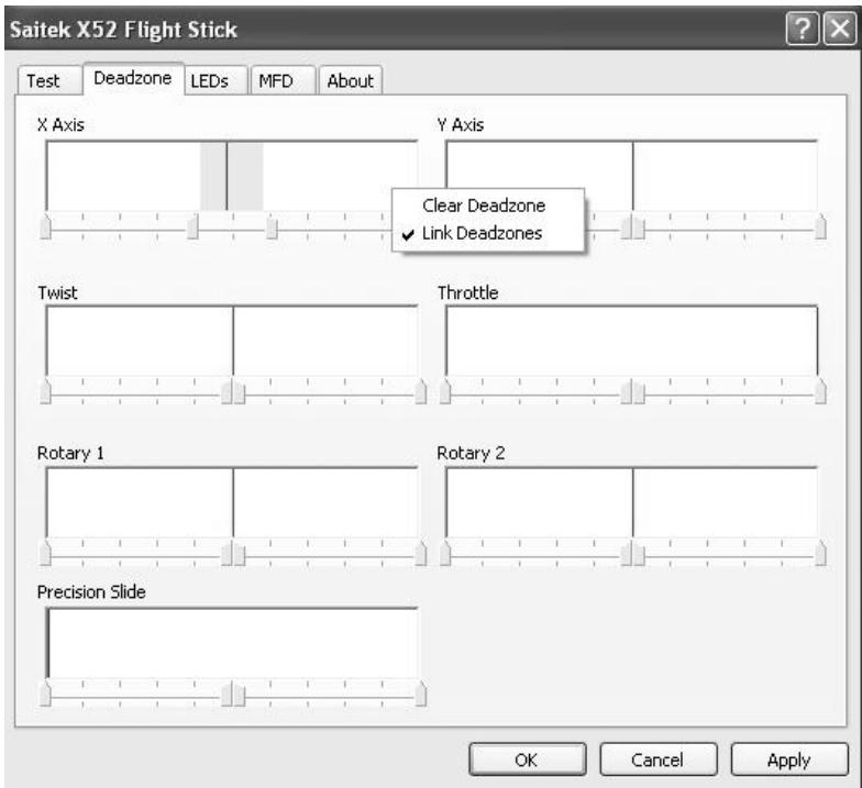
Maintaining deadzones
You can create deadzones for each range and axis your controller features move in. They reduce interference that may be caused by unintended movements of the flight stick and other controls. For example, you may want to move your stick in the X axis only, but find it difficult to avoid moving it in the Y axis as you do so. You can set up a deadzone in the Y axis so that these minor movements are not detected by the drivers.
What is a deadzone?
A deadzone is a part of the range in which an axis moves that is not detected by the drivers and so has no effect on the game in progress. It may be around the center point of the range, or at either end.
To maintain your deadzones
1 Click the Deadzone tab.
The controls you can create deadzones for are shown, as follows:
Each axis is represented by a white box that contains a red line that represents where the control is currently sitting. Moving the corresponding control moves the red line. Use this line to determine exactly where your deadzone must begin and end. Beneath each box is a sliding scale. You use this to specify the size of each deadzone.
2 Click on a slider on the sliding scale and drag it to where you want the deadzone to end. The area that represents the deadzone is shaded gray.
3 Use the center sliders to maintain the deadzone around the center point of an axis. Use the sliders at either end to create deadzones at either end of the axis.
Tips: By default, clicking on either the right or the left slider in the pair moves both sliders. You can change
this if you just want to adjust one side of the deadzone. To do this, right-click anywhere in the white box and select Link Deadzones from the popup list of options displayed. Repeat this to link the pairs of sliders again.
You can clear existing deadzones for an axis by right-clicking anywhere in the white box and selecting Clear Deadzone.
You can maintain deadzones for the following features of the Saitek X52 FCS:
Feature
X Axis
Y Axis
Twist
Throttle
Rotary 1
Rotary 2
Precision Slide
control on the throttle.
Explanation
Movements of the stick from left to right or right to left.
Movements of the stick from back to front or front to back.
Rotations of the stick clockwise and anti-clockwise.
Movements of the throttle to increase or decrease your speed.
Rotations of the small rotary control on the throttle.
Rotations of the large rotary control on the throttle.
Movements of the slide
Maintaining your LED brightness
The authenticity of the flight control experience provided by your Saitek X52 FCS is enhanced by a number of LEDs on the throttle unit and flight stick. You can control the appearance of these LEDs, making them brighter or dimmer according to your preference.
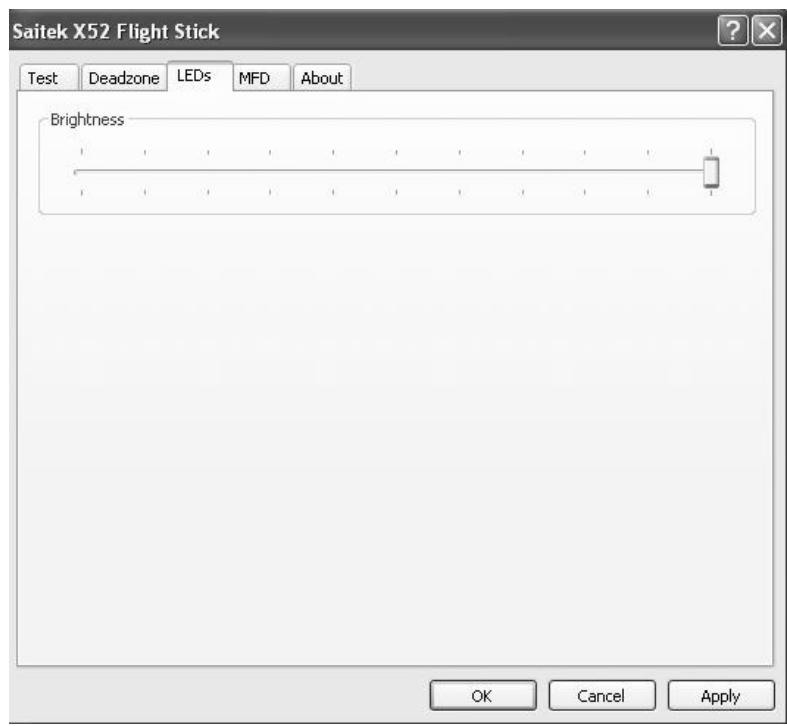
To maintain LED brightness
1 Click the LEDs tab.
A sliding scale is displayed, which you can use to choose how brightly the LEDs on your stick and throttle are displayed:
2 Move the slider on the scale to adjust LED brightness. The LEDs change as you move the slider, so you can make sure they are as you want them to be. You can either:
- Click and drag the slider along the scale. Or:
- Click a point on the scale itself, to move the slider in graduated steps along the scale.
Maintaining MFD settings
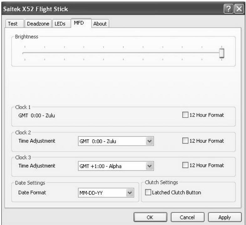
Your Saitek X52 FCS flight stick unit includes an MFD, or Multi-Functional Display. You can control the way information is displayed in your MFD by changing various settings in the MFD tab:
What is the MFD?
The MFD is a screen that displays a variety of different information including, for example, the mode currently selected and today's date. It is part of the same unit as your throttle. The MFD itself and the way it works is explained in more detail in Using the MFD.
To change the brightness of your MFD
1 Click the MFD tab.
A Brightness sliding scale is displayed at the top of the tab.
2 Change the brightness of your MFD by moving the slider along the scale. To move the slider, you can either:
- Click and drag the slider along the scale. Or:
- Click a point on the scale itself, to move the slider in graduated steps along the scale.
The brightness of your MFD changes as you move the slider. Use this to determine when the slider is in the right place.
Maintaining clock settings
Your MFD can display the current time in any time zone. You can choose the time zones displayed and the format in which the time for each zone is displayed.
You can have up to three different time zones available on your MFD. Greenwich Mean Time (GMT) is included by default. You can choose up to two additional time zones. When using your MFD, you switch between the three time zones, as required.
To change your clock settings
1 Click the MFD tab.
This tab includes three panels in which you change the way time is displayed on your MFD. They are called Clock 1, Clock 2 and Clock 3.
Note: Clock 1 is set to GMT by default. You cannot change this.
2 Choose additional time zones that you want to be able to view on your MFD in the Clock 2 and Clock 3 panels. You do this by selecting an option from the corresponding Time Adjustment drop-down list.
Each option is a time relative to GMT, for example GMT +1:00 is GMT plus one hour, and so on. Each time is also represented by an entry in the phonetic alphabet. For example, GMT is represented by 'Zulu' and GMT +12:00 by 'Mike'.
3 Choose the format you want each time to be displayed in. To do this, either check or uncheck the corresponding 12 Hour Format checkbox.
When the box is unchecked, the time is displayed in 24 hour clock format, i.e. between 00:00 and 23:59. If it is checked, the time is shown in 12 hour clock format.
4 Click Apply.
You can now view the current times in your chosen time zones on your MFD. See Using the MFD for details.
Maintaining date settings
The current date is displayed in the bottom right-hand corner of your MFD. You can choose how this date is displayed. You may, for example, prefer to see the month first, followed by day and year.
To change your date settings
1 Click the MFD tab.
The format the date is currently displayed in on your MFD is shown in the Date Settings panel.
2 Select the format you want the date to be displayed in from the drop-down list.
3 Click Apply.
Changing the way your clutch button works
The clutch button on your throttle is used to temporarily deactivate the buttons in the game in progress. This enables you to check what each button does without interrupting the game, and to select a different profile if required. See Viewing button names in Using the MFD for more information.
To change the way your clutch works, check or uncheck the Latched Clutch Button checkbox in the Clutch Settings panel and then click Apply.
When the box is checked, pressing and releasing the clutch deactivates the buttons in the game in progress. To re-activate the buttons, you must press and release the clutch again.
When the box is unchecked, the buttons are deactivated in the game only as long as the clutch is depressed. When you release the clutch, pressing buttons once again affects the game in progress.
Viewing notes and version information
Useful information about the SST programming software, along with a link by which you can download the latest version of the software, is provided. You can also view details
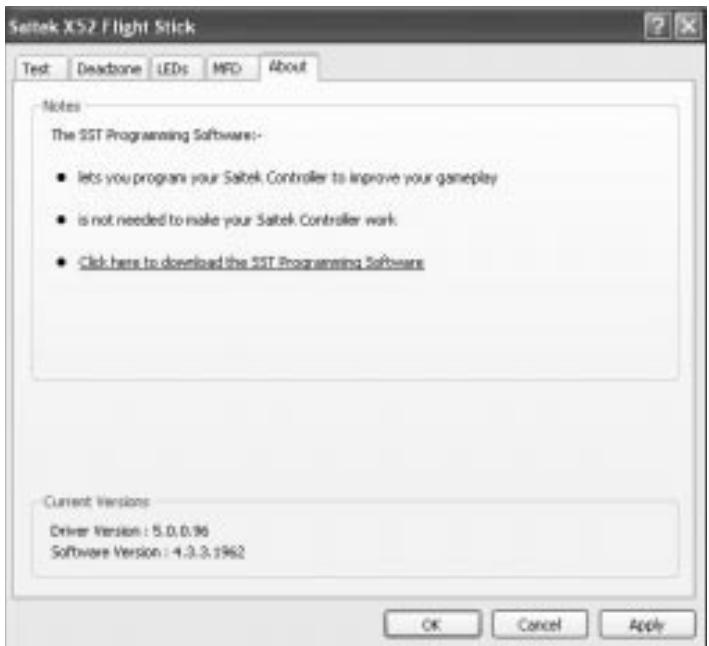
of the driver and software versions that you currently have installed.
To view this information, click the About tab. This tab is shown above:
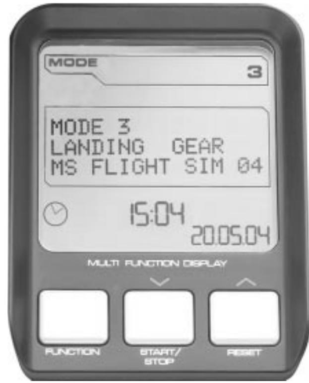
Using the MFD
The MFD, or Multi-Functional Display, is an integral part of your throttle unit. It displays a variety of information including button names, the current profile and today's date. It also provides a stopwatch feature.
You can change some of the settings that determine the way your MFD works. For example, you may want to increase
the brightness of the display, or change the way the date is shown.
You do this in the MFD tab of the Saitek X52 Flight Stick Properties window. See Maintaining MFD settings in the section Maintaining your controller settings for more information.
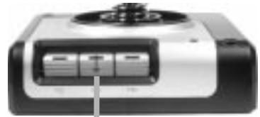
Features of the MFD
The MFD is divided into three sections:
- The mode section is at the top of the MFD and shows the currently selected mode. See Working with modes, below.
- The center section of the MFD is used to view the names of buttons on your flight stick and throttle, and to view and change the current profile. See Working with profile information, below.
- The time and date display is at the bottom of the MFD. It can show the current time in up to three time zones. It also includes the stopwatch. See Viewing the time and date and Using the stopwatch, below.
The layout of the MFD is shown right:
The three buttons beneath the MFD are used to change the time display and to operate the stopwatch.
Working with modes
The Saitek X52 FCS offers extensive opportunities for you to configure your controller to work the way you want it to. You do this by creating profiles, using the SST programming software. (See the SST programming software manual for details.) Within each profile,
you can create up to six different modes that determine the actions performed when you press buttons on the flight stick and throttle.
You can use your MFD to view the mode that is currently selected.
Changing the mode
You change the mode by rotating the mode selector switch on your flight stick. As you do this, the MODE number displayed on the MFD changes to reflect your selection.
Using additional modes
Three modes are available by default. You can increase this to six using the pinkie switch on your flight stick. To do this you must designate the pinkie switch to perform the same function as the Shift key, using the SST programming software. You can then select one of the additional modes by holding down the pinkie switch as you rotate the mode selector switch. When you do this, the word SHIFT is displayed in the mode section of your MFD.
Within each profile, you can use the following modes:

Mode 1
Mode 2
Mode 3
Mode 1 + Pinkie
Mode 2 + Pinkie
Mode 3 + Pinkie
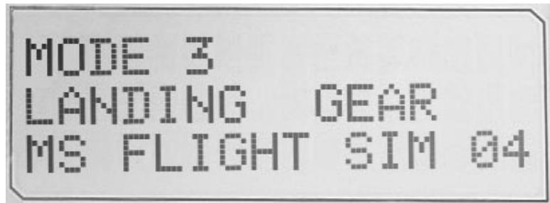
Viewing the current modeThe mode that is currently selected is displayed in the top part of the MFD. This is shown in the following example:
If you have selected one of the three pinkie modes described above, the word SHIFT is displayed, because the pinkie switch is acting as a Shift key.
Working with profile information
You can use the center section of the MFD to view the names assigned to buttons on your flight stick and throttle. It also shows the names of the profile and mode currently selected.
Viewing button names
You can view the names assigned to buttons in the current mode. You may use the SST programming software to create a number of profiles. Each profile may include up to six different modes, assigning different functions to individual buttons for use in different games.
If you've created profiles, you can view the names you've given to buttons in the selected mode in the current profile. If not, the standard name assigned to each button is displayed. The standard name reflects the function assigned to each button when your Saitek X52 FCS is supplied.
To view the name of a button, press it as you normally would. Its name is displayed in the centreline of the MFD. If a game is in progress, use the clutch to deactivate the buttons in the game. You can then press them and view their names without affecting the game. When supplied, the clutch is set up so that you must keep it depressed for as long as you want the buttons to remain inactive in the current game. You can change the way the clutch button works via the MFD tab of the Saitek X52 Flight Stick properties window. See Changing the way your clutch button works in Maintaining your controller settings for details.
Note: You cannot view button names if the Saitek X52 Flight Stick properties window is open.
Changing the current profile
You can use the MFD to change the current profile 'on the fly'. You may, for example, realise that you're not working in the correct profile for the game in progress.
To change the profile on the fly
1 Press the clutch button. The LEDs on your clutch and on the main POV control on your flight stick begin to flash on and off. Pressing buttons does not affect the game in progress when the clutch is engaged.
Note: When supplied, the clutch is set up so that you must keep it depressed for as long as you want it to be engaged. You can change the way the clutch works via the MFD tab of the Saitek X52 Flight Stick properties window. See Changing the way your clutch button works in Maintaining your controller settings for details.
2 Move the main POV control on your flight stick up (north) or down (south) to scroll through your profiles. As you do this, the profile names are displayed in the bottom row of the centre section of the MFD.
Note: You can use the MFD to access any folder on your computer. To open a folder, push the POV to the right (east). To move up a level, scroll through the files and folders in the current folder until [...] is displayed, and then push the POV to the right (east).

3 Select the profile you want by moving the main POV control right (east) when the profile's name is displayed on the MFD. It becomes the current profile and its settings are applied when you resume the game in progress.
Tip: You can clear the current profile by moving the POV left (west). The buttons on your stick and throttle return to their default settings.
4 Release the clutch. The way you do this depends on your clutch settings. Either stop pressing the clutch button or press and release it.
Viewing the time and date
The lower part of the MFD displays the current time and date:
This part of the MFD can also be used as a stopwatch. You toggle between the two features by pressing the Function button. See Using the stopwatch, below, for more information about this feature.
Viewing the time
You can choose the time zone for which the current time is displayed from up to three available time zones. To move between the available time zones, press the up (Start/Stop) and down (Reset) buttons.
As you move between the three time zones, a number is displayed in the bottom right corner of the MFD (in place of the date). This number disappears after a few seconds.
Greenwich Mean Time (GMT) is available by default, and is represented by the number 1. You can choose which other time zones are available and the format in which each time is displayed. See Maintaining clock settings in the section Maintaining your controller settings for an explanation of this procedure.
Viewing the dateThe date is displayed in the bottom right-hand corner of the MFD. By default, it is shown in the format MMDDYY. You can change the date format, for example to DDMMYY. See Maintaining date settings in the section Maintaining your controller settings for an explanation of this procedure.
Using the stopwatch
The lower part of the MFD can also be used as a stopwatch. You toggle between the stopwatch and time displays by pressing the Function button. When the stopwatch is selected, the following is displayed:
To use the stopwatch
1 Press Start/Stop once. The number of seconds begins to increase.
2 Press Start/Stop again to stop the timer.
3 Press Reset to clear the time and return to 00:00.

Note: The timer initially shows minutes and seconds. If the time recorded reaches fifty-nine minutes and fifty-nine seconds, i.e. 59:59, it changes to show hours and minutes. This means the next reading after 59:59 is 01:00.
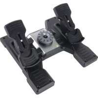
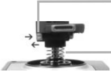
Using the rudder lock
You can deactivate the rudder feature on your flight stick by engaging the rudder lock. When you do this, the flight stick no longer rotates.
To use the rudder lock
1 Position your flight stick unit with the three toggle switches (T1 to T6) facing you. The rudder lock can be seen at the base of the flight stick, on the left hand side. If you look closer, you will see that it is labelled RLOCK.
2 Pull out the RLOCK switch. You may find the easiest way to do this is by using the thumb on your left hand. The twist action on the flight stick is now locked and you can no longer rotate it. You can restore the rudder feature at any time by pushing the RLOCK switch back in.
Adjusting the handle
You can optimise your comfort when using the flight stick by adjusting the height of the hand rest and pinkie switch. If your hands are small, you can place the hand rest and pinkie switch in the highest position available. This reduces the distance between the trigger switch and pinkie switch, avoiding the need for you to stretch to reach both. If you have larger hands, you can maximise this distance and operate the flight stick in greater comfort.
To adjust the handle
1 Position your flight stick unit with the three toggle switches (T1 to T6) facing away from you. A metal screw is clearly visible about one third of the way up the back of the handle.
2 Loosen the screw by turning it anti-clockwise. When the screw is loose enough, you can move it freely up and down within its slot on the back of the handle. Moving the screw also moves the hand rest and pinkie switch.
3 Move the screw until the hand rest and pinkie switch are at the height you want.
4 Place the screw in the position that best suits your preferred height. There are five positions for you to choose from.
5 Tighten the screw in position by turning it clockwise.
ROGER WILCO SOFTWARE
Roger Wilco is a "virtual walkie-talkie" that let's you talk to your friends as you play online games.
Highlights
Simple to use
Sound quality is equivalent or better than a CB radio.
- Works with hundreds of Windows games.
Support for web integration and ICQ integration (Windows)
Windows Game Developer Tools.
Built-in channel browser to help you find other chatters
Disclaimer:
Roger Wilco is the property of GameSpy Industries and as such Saitek plc accepts no responsibility for this product. Any queries relating to this product should be directed to GameSpy Industries.
IMPORTANT INFORMATION
Important notice for Windows® XP users
If you have updated Windows XP to Service Pack 2 the following screen will appear when installing the Saitek Magic Mouse and Keyboard:
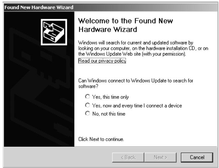
At this point we recommend that you select the No, not this time option and then click on Next to carry on with the installation.
A WORD ON DRIVER UPDATES
From time to time there may be updates to the driver and programming software for this product. You can check for the latest software updates by visiting the Saitek website and clicking on Downloads. A drop down menu will appear. Select Drivers and Software.
FOR WINDOWS® XP USERS; DYNAMIC UPDATES:
You can check for Driver updates using Windows update. Click on Start on the bottom left hand corner of your monitor and then select Windows Update from the menu. Click on Driver Updates then select from any of the update options that appear in the centre of the window. When you have selected the relevant file to download go to the left hand side of the window and select Review and Install Updates. Finally click on Install Now from the centre section.
If you are using the SST Programming software then you will need to obtain an updated version to work with the new drivers that you have downloaded from Windows update. To obtain the new version of the software, open the Game Controllers icon in Control Panel, select the controller in the window and click Properties. At the top of the Properties window click the About tab and you will see a link that says "Click here to download the SST Programming Software". Click on the link and Windows will give a download prompt asking if you want to open the file or save it. Choose to save it to your preferred location on your computer's hard disk and the file will start downloading. Once the file has downloaded, find it on your hard disk and double click on it to install the programming software.
ENABLING YOUR CONTROLLER IN GAME
Most games support game controllers, which you can enable by using a [control] options menu within the Main Menu of the game itself. If you are having trouble working out how to do this or if you're unsure whether the game being used supports game controllers, please refer to the user manual for that game for more help.
NOTE: Even if the game you are using does not support game controllers, it is possible to make the controller work in that game using the Saitek Smart Technology programming software (only installed if you chose to be an Advanced User when installing). Using the programming software allows you to program your controller with keyboard and mouse commands, enabling it to work in those games that only have support for keyboards and mice. For help using this powerful programming software, consult the Programming Your Saitek Controller with Saitek Smart Technology Programming Software section in this manual.
TROUBLESHOOTING
Q My computer is not recognizing the Saitek Controller – what's wrong?
A 1. Have you installed the drivers on the CD supplied with this product?
2. Check the cable connections. Unplug your controller and plug it back in, making certain that it is securely attached.
3. Have you tested your controller? Please refer to the "How to Test Your Controller" section in this manual for further information
Q2 The game I am playing does not recognize my controller - what's wrong?
A 1. Ensure that you have conducted the checks in Q1 [above]
2. Does the game you are playing offer support for game controllers? Please refer to the "Enabling Your Controller in Game" section in this manual for further information.
- You can do this at any time by Clicking on Start, then Settings and selecting Control Panel in Windows (XP users may only need to click on Start and then Control Panel)
- Look for an icon called either Game Controllers or Gaming Options (XP users may have to click Printers and Other Hardware first).
- Open the Game Controllers/Gaming Options window then the name your controller should show up.
- Click on Properties and this will bring up the test screen.
- Moving your controller and pressing the buttons should result in a response in this screen; if it's responding in there then you know that the controller is okay.
PROGRAMMING YOUR SAITEK CONTROLLER WITH SAITEK SMART TECHNOLOGY PROGRAMMING SOFTWARE
Introducing Saitek Smart Technology Programming Software
Saitek Smart Technology Programming Software (SST) is the software Saitek supplies to configure your Saitek controller for enhanced functionality. SST delivers a powerful set of features, allowing you to program your device with the ultimate configuration for total interaction. Despite a level of sophistication previously unseen in the market, and because of the Saitek Smart Technology inside, the software remains simple and intuitive to use.
Features of Smart Technology Programming Software:
Quick and easy setup in any game
- Personalize the controller settings for your favorite games
- Configure your controller with an on-screen 3D model and interface
- Multiple setup option for each controller - ideal if a controller is used by several people
- Program special moves with sophisticated timing features
Special game setups available as 'Profiles' from the Saitek website and on the Smart Technology CD
Download the latest version of Saitek Smart Technology software from the Saitek website
What is a Profile?
A Profile is a custom setup for improved gameplay – consisting of a set of commands that are pre-assigned to the buttons or axes of your controller. We have provided some profiles for popular games on the Product Companion CD that accompanies your device. These profiles should be copied to the C:\Program Files\Saitek\Software directory on your PC before use. You can then open them from within the Profile Editor software by clicking File>Oper, at the top of the window; select the profile you wish to edit and then click Open.
How Do I Program My Controller?
After getting to know your controller, you can start creating your own personal Profiles with the Saitek Smart Technology programming software (SST). This software has virtually unlimited programming capabilities and allows you to customize the controller to your exact gaming needs.
The Profile Editor allows you to program the buttons on your controller to perform different actions within your games – this is especially useful if the game you are using does not have its own screen that allows reconfiguring of your buttons.
Getting Started
1 Double-click on the Saitek Smart Technology icon the install left on your desktop.
2 In the Profile Editor, choose the control to which you wish to assign a keyboard command. You do this by left-clicking on the control's cell in the control list on the right of the screen.
3 With the cursor flashing, type in the key commands and then click on the green tick mark when complete.
4 Repeat this procedure for all the buttons you would like to program and then click File, Save at the top of the Profile Editor window.
5 Give the profile a name (it is recommended you name it after the game for which the profile is intended) and then click Save.
To enable the profile either click the Profile Now icon at the top of the Profile Editor (it looks like a black and yellow crosshair) or right-click on the controller icon in your taskbar and select the name of the profile from the pop-up list of options.
7 You will notice that when a profile is loaded that the controller icon in your taskbar has a green square behind it, indicating that a profile is currently loaded. If you wish to unload a profile simply right-click on the controller icon and click Clear Profile from the pop-up list of options.
If you require more detailed assistance with using the SST Programming Software, click on Help at the top of the Profile Editor and then Manual.
TECHNICAL SUPPORT
Can't get your joystick to work - don't worry, we're here to help you!
Nearly all the products that are returned to us as faulty are not faulty at all - they have just not been installed properly.
If you experience any difficulty with this product, please first visit our website www.saitek.com. The technical support area will provide you with all the information you need to get the most out of your product and should solve any problems you might have.
If you do not have access to the internet, or if the website cannot answer your question, please contact your local Saitek Technical Support Team. We aim to offer quick, comprehensive and thorough technical support to all our users so, before you call, please make sure you have all the relevant information at hand.
To find your local Saitek Technical Support Center, please see the separate Technical Support Center sheet that came packaged with this product.
Conditions of Warranty
1 Warranty period is 2 years from date of purchase with proof of purchase submitted.
2 Operating instructions must be followed.
3 Product must not have been damaged as a result of defacement, misuse, abuse, neglect, accident, destruction or alteration of the serial number, improper electrical voltages or currents, repair, alteration or maintenance by any person or party other than our own service facility or an authorized service center, use or installation of non-Saitek replacement parts in the product or the modification of this product in any way, or the incorporation of this product into any other products, or damage to the product caused by accident, fire, floods, lightning, or acts of God, or any use violative of instructions furnished by Saitek plc.
4 Obligations of Saitek shall be limited to repair or replacement with the same or similar unit, at our option. To obtain repairs under this warranty, present the product and proof of purchase (e.g. bill or invoice) to the authorized Saitek Technical Support Center (listed on the separate sheet packaged with this product) transportation charges prepaid. Any requirements that conflict with any state or Federal laws, rules and/or obligations shall not be enforceable in that particular territory and Saitek will adhere to those laws, rules, and/or obligations.
5 When returning the product for repair, please pack it very carefully, preferably using the original packaging materials. Please also include an explanatory note.
6 IMPORTANT: To save yourself unnecessary cost and inconvenience, please check carefully that you have read and followed the instructions in this manual.
7 This warranty is in Lieu of all other expressed warranties, obligations or liabilities. ANY IMplied WARRANTY, OBLIGATIONS, OR LIABILITIES, INCLUDING BUT NOT LIMITED TO THE IMplied WARRANTIES OF MERCHANTABILITY AND FITNESS FOR A PARTICULAR PURPOSE, SHALL BE LIMITED IN DURATION TO THE DURATION OF THIS WRITTEN LIMITED WARRANTY. Some states do not allow limitations on how long an implied warranty lasts, so the above limitations may not apply to you. IN NO EVENT SHALL WE BE LIABLE FOR ANY SPECIAL OR CONSEQUENTIAL DAMAGES FOR BREACH OF THIS OR ANY OTHER WARRANTY, EXPRESS OR IMPLIED, WHATSOEVER Some states do not allow the exclusion or limitation of special, incidental or consequential damages, so the above limitation may not apply to you. This warranty gives you specific legal rights, and you may also have other rights which vary from state to state.
FCC Compliance and Advisory Statement
Warning: Changes or modifications to this unit not expressly approved by the party responsible for compliance could void the user's authority to operate the equipment.
This device complies with Part 15 of the FCC Rules. Operation is subject to the following two conditions:
1 This device may not cause harmful interference, and
2 This device must accept any interference received, including interference that may cause undesired operation
NOTE: This equipment has been tested and found to comply with the limits for a Class B digital device, pursuant to Part 15 of the FCC Rules. These limits are designed to provide reasonable protection against harmful interference in a residential installation. This equipment generates, uses and can radiate radio frequency energy and, if not installed and used in accordance with the instructions, may cause harmful interference to radio communications. However, there is no guarantee that interference will not occur in a particular installation. If this equipment does cause harmful interference to radio or television reception, which can be determined by turning the equipment off and on, the user is encouraged to try to correct the interference by one or more of the following measures:
Reorient or relocate the receiving antenna
- Increase the separation between the equipment and receiver
- Connect the equipment into an outlet on a circuit different from that to which the receiver is connected
- Consult the dealer or an experienced radio/TV technician for help
Saitek Industries, 2295 Jefferson Street, Torrance, CA 90501, USA
Canadian EMC statement
This Class B digital apparatus complies with Canadian ICES-003.
These Installations will be developed by the Saitek Controller, which will be responsible for the development of the IoT and control systems.