03KOS - Pressure washer NILFISK - Free user manual and instructions
Find the device manual for free 03KOS NILFISK in PDF.
User questions about 03KOS NILFISK
0 question about this device. Answer the ones you know or ask your own.
Ask a new question about this device
Download the instructions for your Pressure washer in PDF format for free! Find your manual 03KOS - NILFISK and take your electronic device back in hand. On this page are published all the documents necessary for the use of your device. 03KOS by NILFISK.
USER MANUAL 03KOS NILFISK
4.0 Standardutrusting
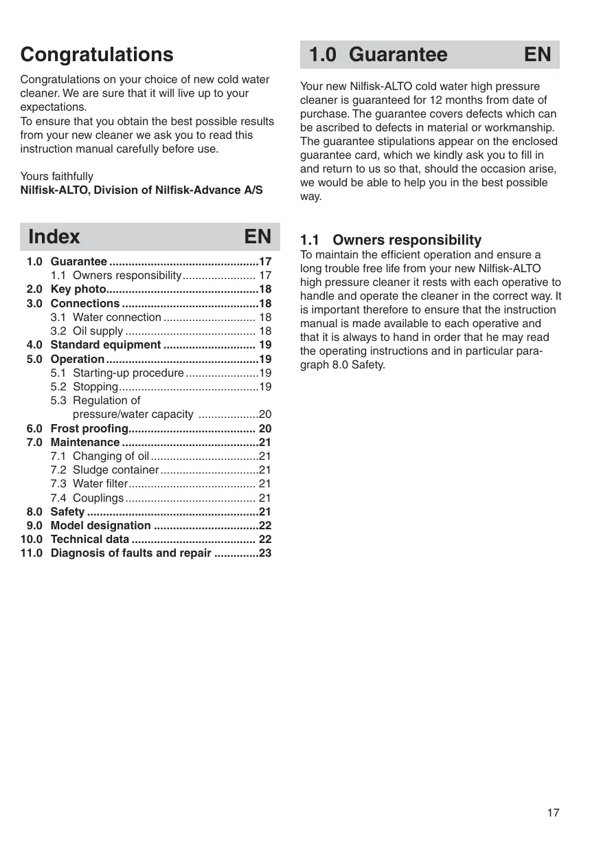
Congratulations on your choice of new cold water cleaner. We are sure that it will live up to your expectations.
To ensure that you obtain the best possible results from your new cleaner we ask you to read this instruction manual carefully before use.
Yours faithfully
Nilfisk-ALTO, Division of Nilfisk-Advance A/S
Index EN
1.0 Guarantee 17
1.1 Owners responsibility 17
2.0 Key photo.. 18
3.0 Connections 18
3.1 Water connection 18
3.2 Oil supply 18
4.0 Standard equipment 19
5.0 Operation 19
5.1 Starting-up procedure 19
5.2 Stopping 19
5.3 Regulation of pressure/water capacity 20
6.0 Frost proofing 20
7.0 Maintenance 21
7.1 Changing of oil 21
7.2 Sludge container 21
7.3 Water filter.. 21
7.4 Couplings 21
8.0 Safety 21
9.0 Model designation 22
10.0 Technical data 22
11.0 Diagnosis of faults and repair 23
1.0 Guarantee EN
Your new Nilfisk-ALTO cold water high pressure cleaner is guaranteed for 12 months from date of purchase. The guarantee covers defects which can be ascribed to defects in material or workmanship. The guarantee stipulations appear on the enclosed guarantee card, which we kindly ask you to fill in and return to us so that, should the occasion arise, we would be able to help you in the best possible way.
1.1 Owners responsibility
To maintain the efficient operation and ensure a long trouble free life from your new Nilfisk-ALTO high pressure cleaner it rests with each operative to handle and operate the cleaner in the correct way. It is important therefore to ensure that the instruction manual is made available to each operative and that it is always to hand in order that he may read the operating instructions and in particular paragraph 8.0 Safety.
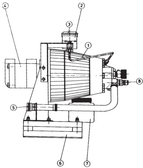
2.0 Key Photo
4403KO Stationary unit
- Pump
- Manometer
- Oil filling
- Hydraulic motor
- Water inlet
- Vibration damper
- Sludge container
- Water outlet
3.0 Connections
EN
3.1 Water connection
The water input is connected at the back of the machine. The machine can be connected directly to the mains water supply, or it can work as a self-priming unit*).
For direct water connection the inlet hose must be at least 6m long, and the water temperature must not exceed 65^ . Please note that connection to the public water supply may entail mounting of a float chamber.
If there is sand or other impurities in the water, it is advisable to provide an external water filter in addition to the internal filter situated behind the quick coupling (see accessory catalogue).
3.2 Oil supply
Connect the hydraulic motor to a hydraulic supply with a capacity of 43I / min by 94-100 bar.
If the return pipe pressure exceeds 1.5 bar the drain pipe should be conducted separately.
*) With cold water (up to 5^ ) the cleaner will operate satisfactorily with up to a 5 metre difference of level between cleaner and water supply. The pump and the inlet hose must be connected to the water supply before starting up. When working with hot water (65^) the cleaner must be below or on a level with the point of water supply. Working with hot water and connected to high pressure hoses longer than 10m or inlet hoses shorter than 6m , the cleaner must be equipped with a float chamber. The same applies if the outlet of the cleaner is connected to a tube system.
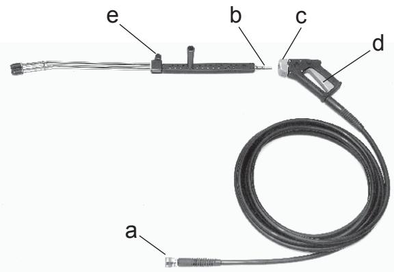
4.0 Standard equipment
The cleaner is delivered with a double lance and a spray handle together with high pressure hose as standard equipment. The low pressure tube is equipped with a flat jet nozzle 6530 and the high pressure hose with a flat jet nozzle 1506. The first two figures of the nozzle reference number indicate the spray angle in degrees and the last two indicate the water flow in l/min. at a pressure of 20 bar and a temperature of 20^ . The equivalent hole diameters for nozzle 1506 is 1.6mm and for nozzle 6530 is 3.6mm . Do not replace with nozzles of a smaller diameter. The maximum working pressure and temperature are printed on the standard high pressure hose. Only use Nilfisk-ALTO high pressure hoses. In case of damage, arrange for Nilfisk-ALTO service engineers to repair it. Do not attempt to repair it yourself.
The thrust on the nozzle is for:
4403KOS
47N
(4.8 k p)
As the thrust forms an angle with the spray lance, the spray handle is subject to torque.
5.0 Operation
EN
5.1 Starting-up procedure
- Check the oil level in the oil glass. The level should be maintained between the MIN. and MAX. marks.
- Run water through the inlet hose before connecting, in order to remove possible impurities in the hose. Connect the hose.
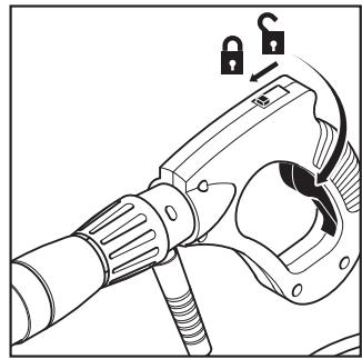
- Connect the quick coupling (a) of the high pressure hose to the outlet socket.
- Check the input end of the spray lance (b) for possible impurities. Pull forward the grey trigger (c) of the spray handle. Connect the input end of the spray lance to the quick coupling. Release the grey trigger.
- Press the trigger of the spray handle (d) and allow the water to run, until the system has been completely vented. For self-priming it is recommended to open the regulating valve (e) during the venting.
- Release the trigger of the spray handle (d) and turn on the hydraulic supply. The pump will now be in idle motion.
- For cleaning at high pressure press home the trigger of the spray handle after having closed the regulating valve.
- For cleaning at low pressure open the regulating valve.
5.2 Stopping
- Turn off the hydraulic supply.
- Turn off the water supply and disconnect the hoses.
- Do not disconnect the high pressure hose, until the cleaner has cooled down and stopped.
5.3 Regulation of pressure/water capacity
When working at the maximum working pressure the regulating valve of the spray lance must be completely closed, and the valve for regulation of the water capacity must be unscrewed (in the direction indicated by the arrow).
The water capacity is continuously variable between min. and max. according to the diagram below.
Close the spray handle, screw in the valve for regulation of the water capacity (in the opposite direction of that indicated by the arrow). This corresponds to a working pressure of 40 bar and a water capacity of about 9l / min
If increased water output is required, turn the valve in the direction indicated by the arrow, until the required amount is reached. 1 turn is equivalent to a rise of pressure of approx. 50 bar.
If fully reduced pressure with maximum water output is required, open the regulating valve. The water will now flow from both tubes at a pressure of approx. 5 bar.
This can be done irrespective of the adjustment of the valve for regulation of the water capacity.
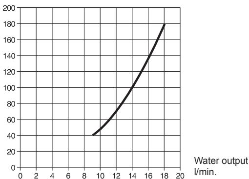
Pressure (bar)
Operation and storage in frosty weather (below 0^ ).
Never leave the cleaner unless it has been emptied of water, not even for a short period. Empty the cleaner in the following way:
- Disconnect and empty both the water supply and the high pressure hoses.
- Start the pump and allow it to run until it is empty.
If the cleaner is not stored in a frost-proof place between operations, it should be protected from frost in the following way:
- Disconnect the lance.
- Start the machine and allow it to run without water.
- Place the suction hose into a container of anti-freeze.
- Draw in the antifreeze from the container by activating the spray handle. Having placed the spray handle above the antifreeze funnel, open and close it a few times, so that the antifreeze can circulate.
- Remove the inlet hose from the container. Activate the spray handle and allow the rest of the antifreeze to run back into the container.
NB! The antifreeze will be diluted with water and will after some time lose its effect.
IMPORTANT:
To avoid damage always ensure that the cleaner, the hoses and the spray lance are unfrozen before restarting. Place the cleaner and the accessories in a warm place for some time before starting up.
7.0 Maintenance
EN
8.0 Safety
EN
7.1 Changing of oil
The oil should be changed after each 1000 hours' use.
Remove the cover of the oil glass. Unscrew the drain plug. Allow the oil to run out and clean the drain plug of impurities. Screw in the plug and refill the pump with fresh oil through the oil glass. Holds approx. 1 l.
From Nilfisk-ALTO the pump is filled with zincless hydraulic oil - Nilfisk-ALTO Pump Oil 100. When refilling and changing the oil this or an oil with the following specifications should be used:
ISO no. 100
Viscosity index (VI) min. 130
Pour point below -30^
7.2 Sludge container
The used oil is caught in a sludge container, which should be emptied before it is completely full. The oil must not be reused in the pump.
7.3 Water filter
To avoid debris entering the high pressure pump a water filter is fitted at the water inlet. This filter must be taken apart and cleaned regularly. The intervals between cleaning depend on the purity of the water. The filter can be removed, when the quick coupling has been unscrewed.
7.4 Couplings
To avoid leakages and damage to the quick couplings on hoses, spray handle and spray lance it is necessary to clean and lubricate the parts regularly with a little oil or grease.
Your Nilfisk-ALTO cold water cleaner is designed and manufactured to comply with the very latest labour regulations.
Nevertheless, the following instructions must be strictly observed.
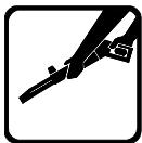
- Always hold the spray handle and lance firmly in both hands during operation at high pressure.
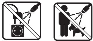
- Never direct the high pressure spray towards people or electrical devices.
- When not in use; lock the spray handle.
- Only use the hoses and nozzles approved by Nifisk-ALTO.
- Do not disconnect the high pressure hose until the cleaner has cooled down and stopped.
- Don't attempt to touch nozzle nor water jet during operation.
- Never tie knots in or kink the high pressure hose as it may be damaged and consequently burst.
- Do not leave your machine exposed to frost. However if cleaner, hose or lance should become frozen do not use until they have thawed.
- The high pressure pump features a safety valve, the adjustment of which SHOULD NOT BE CHANGED.
- The machine should only be used by people who have been properly instructed.
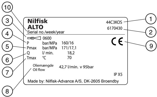
9.0 Model designation
The Nilfisk-ALTO 03K-series of cold water cleaners is produced in several models. The model designation is printed on the model plate, e.g. Nilfisk-ALTO 4403KOS. This plate provides the following details.
- Model designation
- Nilfisk-ALTO order no.
- Nozzle
- Pump pressure
- Max. pressure
- Water capacity
- Max. temp. of inlet water
- Oil flow
- Approval
- Serial number, production week and -year
EN
10.0 Technical data
| Model | 4403KOS | |
| Cleaning power adjustable max. | kW/hp | 4.4/5.9 |
| Pump pressure max. | bar/psi | 160/2320 |
| Nozzle pressure, adjustable min./max. | bar/psi | 4/152 - 58/2200 |
| Water capacity at min./max. pressure | l/min.-ImpG/min. | 19.1/17.3 - 4.2/3.8 |
| Min. water capacity (at 40 bar/580 psi) | l/min.-ImpG/min. | 9-2 |
| Self-priming, max. suction height | m/ft | 5/16 |
| Max. temp. of inlet water | °C/°F | 65/150 |
| High pressure hose, length | m/ft | 10/33 |
| Nozzle sizes | 0640 | |
| Dimensions: | length | mm/inch |
| width | mm/inch | |
| height | mm | |
| Weight complete, incl. of oil | kg/lb | 43,5 / 95.9 |
| Motor | type | |
| Oil consumption at 95 bar/1380 psi | l/min-ImpG/min. | 42.7/9.4 |
Sound pressure level L_pA measured in accordance with ISO 11202 [DISTANCE 1M] [FULL LOAD]: 80 dB(A) We reserve the right to amend the specifications.
11.0 Diagnosis of faults and repair
EN
| Fault | Cause | Repair |
| The motor fails to start | Oil supply not connected | Connect the oil hose. |
| Oil supply closed | Open the valve. | |
| No oil pressure | Start the hydraulic pump. | |
| The pump is frozen | Let the pump thaw. | |
| Working pressure too high | Nozzle partly blocked | Clean the nozzle. |
| Working pressure too low | Valve for regulation of water capacity is not adjusted to max. pressure | Open fully the valve for regulation of water. Turn in the direction indicated by the arrow. |
| Regulating valve open | Close the regulating valve. | |
| Irregular working pressure | Air in the pump | Repeat the venting procedure. |
| During self-priming | Suction height too high or water too hot | Read the paragraph 3.1 conc. self-priming. |
| Filter blocked | Clean the filter. See paragraph 7.3. | |
| During direct water connection | Insufficient water supply from the water works | Change to a water supply with greater output. If this is not possible; turn the valve for regulation of the water capacity in the opposite direction of that indicated by the arrow, until the machine works smoothly. |
| No working pressure | Nozzle blocked | Clean the nozzle. |
| No water | Check the water connection. | |
| High pressure hose/lance frozen | Allow the high pressure hose/lance to thaw. | |
| By-pass valve frozen | Allow the machine to thaw. |
Should faults occur other than those mentioned above, please contact the nearest Nilfisk-ALTO service organization.
Wir gratulieren
Riverside Business Park
Boulevard Internationalelaan 55
Building 18, Suchun Industrial Estate
Suzhou Industrial Park
215021 Suzhou
Tel.: (+86) 512 6265 2525
CZECH REPUBLIC
Nilfisk-Advance
VGP Park Horní Pocernice
Do Certous 1/2658
193 00 Praha 9
Tel.: (+420) 24 14 08 419
DENMARK
Nilfisk-Advance A/S
Industrivej 1
9560 Hadsund
Tel.: +45 7218 2100
E-mail: salg.dk@nilfisk-advance.com
FINLAND
31-39 Wo Tong Tsui Street
Kvai Chung
Tel.: (+852) 24 27 59 51
HUNGARY
Nilfisk-Advance Kereskedelmi Kft.
349, Business Point,
No 201,2nd floor, above Popular Car World,
Western Express High way, Andheri ( East),
Mumbai - 400 069
Tel.: (+91) 223 2174592
IRELAND
Nilfisk-Advance
1 Stokes Place
St. Stephen's Green
Dublin 2
Tel.: (+35) 312943838
ITALY
Nilfisk-Advance SpA
Division of Nilfisk-Advance
Bjornerudveien 24
1266 Oslo
Tel.: (+47) 22 75 17 70
E-mail: info.no@nilfisk-alto.com
POLAND
Nilfisk-Advance Sp. Z.O.O.
05-800 Pruszkowski
ul.3-go MAJA 8
Tel.: +48 22 738 37 50
PORTUGAL
Nilfisk-Advance
Sintra Business Park
Zona Industrial Da Abrunheira
Edificio 1, 1^ A
P2710-089 Sintra
Tel.: +35 121 911 2670
E-mail: mkt.pt@nilfisk-advance.com
RUSSIA
HnΦnck-3DbaHc
127015 MockBa
Bartckayy.27,ctp.7
Pocn
Tel.: (+7) 495 783 96 02
E-mail: info@nilfisk.ru
SINGAPORE
Nilfisk-Advance Pte. Ltd.
40 Loyang Drive
Singapore 508961
Tel.: (+65) 6759 9100
SPAIN
Nilfisk-Advance S.A.
Torre D'Ara
Paseo del Ringle, 5 Pl.10
08302 Mataró
Tel.: (+3) 4937412400
E-mail: mkt.es@nilfisk-dvance.com
SWEDEN
Nilfisk-ALTO
Division of Nilfisk-Advance
Aminogatan 18
Box 40 29
431 04 Molndal
Tel.: (+46) 317067300
E-mail: info.se@nilfisk-alto.com
SWITZERLAND
Nilfisk-Advance
Ringstrasse 19
Kircheberg/Industri Stezzi
9500 Wil
Tel.: (+41) 719 23 84 44
E-mail: info.ch@nilfisk-advance.com
TAIWAN
Nilfisk-Advance Taiwan Branch
1F, No. 193, sec. 2, Xing Long Rd.
Taipei
Tel.: (+88) 6227 002 268
THAILAND
Nilfisk-Advance Co. Ltd.
89 Soi Chokechai-Ruammitr
Viphavadee-Rangsit Road
Ladyao, Jatuchak, Bangkok 10900
Tel.: (+66) 2 275 5630
TURKEY
Nilfisk-Advance Profesional Temizlik
Hillside Business Park
Kempson Way
Bury St. Edmunds
Suffolk IP32 7EA
Tel.: (+49) 01284 763163
E-mail: sales.uk@nilfisk-advance.com
UNITED ARAB EMIRATES
Nilfisk-Advance Middle East Branch
SAIF-Zone
P.O.Box 122298
Sharjah
Tel.: (+971) 553 2626 82
USA
Nilfisk-Advance Inc.
14600 21st Avenue North
Plymouth, MN 55447-3408
Tel.: (+1) 763 745 3500
VIETNAM
Nilfisk-Advance Representative Office
No.51 Doc Ngu Str.
Ba Dinh Dist.
Hanoi
Tel.: (+04) 761 5642
E-mail: nilfisk@vnn.vn