
SW 700S P - Sweeper NILFISK - Free user manual and instructions
Find the device manual for free SW 700S P NILFISK in PDF.

| Product type | Thermal sweeper |
| Brand | NILFISK |
| Model | SW 700S P |
| Cleaning width (with side broom) | 720 mm |
| Cleaning width (without side broom) | 500 mm |
| Dimensions (L x W x H) | 1070 x 667 x 836 mm (handle lowered) |
| Handle height (min/max) | 824 / 1120 mm |
| Total weight | 96 kg |
| Waste container capacity | 40 liters |
| Power source | Honda GX 100 gasoline engine |
| Maximum speed (forward) | 4.4 km/h |
| Maximum climbable slope | 2 % |
| Main broom (diameter x length) | 265 x 500 mm |
| Side broom diameter | 420 mm |
| Dust filter | Paper, 5-10 μm, area 2 m² |
| Main broom housing vacuum | 18 mm H₂O |
| Sound pressure level (ALpa) | 77 dB(A) |
| Hand-arm vibration | 3.3 m/s² |
| Front wheel | 125 / 37.5-50 mm |
| Rear wheels (diameter x width) | 250 x 50 mm |
| Maintenance and cleaning | Empty the container after each use, clean the filter regularly, check the brooms and flaps, change engine oil every 20 h (first time) then every 100 h |
| Safety | Safety switch for trunk opening, automatic engine shutdown if oil level low, optional pedal brake |
| Spare parts and repairability | Use only genuine Nilfisk-Advance parts; contact an authorized after-sales service |
Frequently Asked Questions - SW 700S P NILFISK
User questions about SW 700S P NILFISK
0 question about this device. Answer the ones you know or ask your own.
Ask a new question about this device
Download the instructions for your Sweeper in PDF format for free! Find your manual SW 700S P - NILFISK and take your electronic device back in hand. On this page are published all the documents necessary for the use of your device. SW 700S P by NILFISK.
USER MANUAL SW 700S P NILFISK
The undersigned certify that the above mentioned model is produced in accordance with the following directives and standards.

O KATwI UTOyEvpaMuEvoc TIOToTIOei OTI N TAPayWyn Tou TPOavapePbEvTOc MOvTeLau yivetai ouuawva e TIC akoloueos obnyiecs kai TpOTUTa.

EC Machinery Directive 98/37/EC
EN ISO 12100-1, EN ISO 12100-2, EN 294, EN 349
EC EMC Directive 89/336/EEC
EN 60335-1, EN 60335-2-72
EN 61000, EN 50366
Manufacturer: Nilfisk-Advance S.p.a.
Authorized signatory: Franco Mazzini, General Mgr
Date:
Signature:
INHALTSVERZEICHNIS
EINLEITUNG 2
CONSERVATION DU MANUEL
STRUCTURE DE LA MACHINE
STRUCTURE DE LA MACHINE (suite)
ACCESSIONS / OPTIONS
DEPLACEMENT PAR POUSSEE DE LA MACHINE
REEMPLACEMENT DU BALAI CENTRAL

AVERTISSEMENT!
REEMPLACEMENT DU BALAI LATERAL

AVERTISSEMENT!
MANUAL PURPOSE AND CONTENTS 2
TARGET 2
HOW TO KEEP THIS MANUAL 2
DECLARATION OF CONFORMITY 2
IDENTIFICATION DATA. 2
OTHER REFERENCE MANUALS 2
SPARE PARTS AND MAINTENANCE 3
CHANGES AND IMPROVEMENTS 3
ACCESSIONS/OPTIONS 8
TECHNICAL DATA. 9
WIRING DIAGRAM. 9
USE 10
BEFORE STARTING THE MACHINE 10
STARTING AND STOPPING THE MACHINE 10
AFTER USING THE MACHINE 12
PUSHING THE MACHINE 12
MACHINE LONG INACTIVITY 12
FIRST PERIOD OF USE 12
MAINTENANCE 12
SCHEDULED MAINTENANCE TABLE 13
MAIN BROOM HEIGHT CHECK AND ADJUSTMENT 14
MAIN BROOM REPLACEMENT 15
SIDE BROOM HEIGHT CHECK AND ADJUSTMENT 16
SIDE BROOM REPLACEMENT 16
DUST FILTER CLEANING AND INTEGRITY CHECK 17
SKIRTHEIGHTCHECKANDADJUSTMENT 18
HOOD SAFETY SWITCH OPERATION CHECK 19
TROUBLESHOOTING 20
SCRAPPING 20
INTRODUCTION

NOTE
The numbers in brackets refer to the components shown in Machine Description chapter.
MANUAL PURPOSE AND CONTENTS
The purpose of this Manual is to provide the operator with all necessary information to use the machine properly, in a safe and autonomous way. It contains information about technical data, safety, operation, storage, maintenance, spare parts and disposal. Before performing any procedure on the machine, the operators and qualified technicians must read this Manual carefully. Contact Nilfisk-Advance in case of doubts regarding the interpretation of the instructions and for any further information.
TARGET
This Manual is intended for operators and technicians qualified to perform the machine maintenance.
The operators must not carry out procedures reserved for qualified technicians. Nilfisk-Advance will not be answerable for damages coming from the non-observation of this prohibition.
HOW TO KEEP THIS MANUAL
The User Manual must be kept near the machine, inside an adequate case, away from liquids and other substances that can cause damage to it.
DECLARATION OF CONFORMITY
The declaration of conformity, supplied with the machine, certifies the machine conformity with the law in force.

NOTE
Two copies of the original declaration of conformity are provided together with the machine documentation.
IDENTIFICATION DATA
The machine model and serial number are marked on the plate (41).
The machine model year is written in the declaration of conformity and it is also indicated by the first two figures of the machine serial number.
The petrol engine model and serial number are marked on the plates (42) and (43).
This information is useful when ordering machine and engine spare parts. Use the following table to write down the machine and engine identification data for any further reference.
MACHINE model
MACHINE serial number
ENGINE model
ENGINE serial number
OTHER REFERENCE MANUALS
Other manuals supplied with the machine:
-
Petrol Engine Manual, to be considered an integral part of this Manual.
-
Sweeper Spare Parts List
Other available manuals:
Service Manual (that can be consulted at Nilfisk-Advance Service Centers)
SPARE PARTS AND MAINTENANCE
All necessary operating, maintenance and repair procedures must be carried out by qualified personnel or by Nilfisk-Advance Service Centers. Only original spare parts and accessories must be used.
Contact Nilfisk-Advance for service or to order spare parts and accessories, specifying the machine model and serial number.
CHANGES AND IMPROVEMENTS
Nilfisk-Advance constantly improves its products and reserves the right to make changes and improvements at its discretion without being obliged to apply such benefits to the machines that were previously sold.
Any change and/or addition of accessories must be approved and performed by Nilfisk-Advance.
This sweeper has been designed and built to clean/sweep smooth and solid floors, and to collect dust and light debris, in civil and industrial environments, under safe operation conditions by a qualified operator.
CONVENTIONS
Forward, backward, front, rear, left or right are intended with reference to the operator's position, that is to say with the hands on the handlebar (3).
UNPACKING/DELIVERY
To unpack the machine carefully follow the instructions on the packing.
Upon delivery check that the packing and the machine were not damaged during transportation. In case of visible damages, keep the packing and have it checked by the carrier that delivered it. Call the carrier immediately to fill in a damage claim.
Check that the machine is equipped with the following features:
- Sweeper User Manual
Petrol Engine Manual - Sweeper Spare Parts List
SAFETY
The following symbols indicate potentially dangerous situations. Always read this information carefully and take all necessary precautions to safeguard people and property.
The operator's cooperation is essential in order to prevent injury. No accident prevention program is effective without the total cooperation of the person responsible for the machine operation. Most of the accidents that may occur in a factory, while working or moving around, are caused by failure to comply with the simplest rules for exercising prudence. A careful and prudent operator is the best guarantee against accidents and is essential for successful completion of any prevention program.
SYMBOLS

DANGER!
It indicates a dangerous situation with risk of death for the operator.

WARNING!
It indicates a potential risk of injury for people or damage to objects.

CAUTION!
It indicates a caution or a remark related to important or useful functions. Pay careful attention to the paragraphs marked by this symbol.

NOTE
It indicates a remark related to important or useful functions.

CONSULTATION
It indicates the necessity to refer to the User Manual before performing any procedure.
GENERAL INSTRUCTIONS
Specific warnings and cautions to inform about potential damages to people and machine are shown below.

DANGER!
- Turn the ignition key to "0" and disconnect the batteries before performing any maintenance/repair procedure.
- This machine must be used by properly trained and authorised personnel only. Children or disabled people cannot use this machine.
- Keep the batteries away from sparks, flames and incandescent material. During the normal operation explosive gases are released.
- Do not wear jewels when working near electrical components.
- Do not work under the lifted machine without supporting it with safety stands.
- When working under the open hood, ensure that it cannot be closed by accident.
- Do not operate the machine near toxic, dangerous, flammable and/or explosive powders, liquids or vapours.
- Be careful: fuel is highly flammable.
- Do not smoke or bring naked flames in the area where the machine is refuelled or where the fuel is stored.
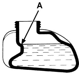
- To allow the fuel to expand, do not fill the fuel tank beyond the upper limit mark (A, Fig. 1).
After refuelling, check that the fuel tank cap is firmly closed.
If any fuel is spilled while refuelling, clean the tank area and allow the vapours to evaporate before starting the engine. - Do not let fuel come into contact with the skin; do not breathe fuel vapours. Keep out of reach of children.
- Do not tilt the engine more than 20^ ; excessive tilting can cause the fuel to come out.
- Do not lay any object on the engine.
- Stop the engine before performing any procedure on it. To avoid any accidental start, disconnect the spark plug cap.
- When lead (WET) batteries are installed, do not tilt the machine for more than 30^ from the horizontal plane to prevent the highly corrosive acid from leaking out of the batteries. When the machine is to be tilted to perform maintenance procedures, remove the batteries.


WARNING!
Carbon monoxide (CO) can cause brain damage or death.
The internal combustion engine of this machine can emit carbon monoxide.
Do not inhale exhaust gas fumes.
Only use indoors when adequate ventilation is provided, and with the help of an assistant.

WARNING!
- Carefully read all the instructions before performing any maintenance/repair procedure.
Take all necessary precautions to prevent hair, jewels and loose clothes from being caught by the machine moving parts. - Do not leave the machine unattended with the key inserted in the ignition switch and the parking brake disengaged.
- Do not use the machine on slopes with a gradient exceeding the specifications.
- Do not use the machine in excessively dusty areas.
- Do not wash the machine with direct or pressurised water jets, or with corrosive substances. Do not use compressed air to clean this type of machine, except for the filters (see the relevant paragraph).
While using this machine, take care not to cause damage to other people, and children especially. - Do not put any can containing fluids on the machine.
- The machine storage temperature must be between 0^ and +40^ .
- The machine working temperature must be between 0^ and +40^ .
- The humidity must be between 30% and 95% .
- Always protect the machine against the sun, rain and bad weather, both under operation and inactivity condition.
- Do not use the machine as a means of transport, or for pushing/towing.
- Do not allow the brooms to operate while the machine is stationary to avoid damaging the floor.
In case of fire, possibly use a powder fire extinguisher, not a water one. - Do not bump into shelves or scaffoldings, especially where there is a risk of falling objects.
- Adjust the operation speed to suit the floor conditions.
- Do not use the machine on slopes with a gradient exceeding the specifications.
- This machine cannot be used on roads or public streets.
- Do not tamper with the machine safety guards.
Follow the routine maintenance procedures scrupulously. - Do not remove or modify the plates affixed to the machine.
In case of machine malfunctions, ensure that these are not due to lack of maintenance. Otherwise, request assistance from the authorised personnel or from an authorised Service Center.
If parts must be replaced, require ORIGINAL spare parts from an Authorised Dealer or Retailer. - To ensure machine proper and safe operation, the scheduled maintenance shown in the relevant chapter of this Manual must be performed by the authorised personnel or by an authorised Service Center.
- The machine must be disposed of properly, because of the presence of toxic-harmful materials (batteries, oils, plastics, etc.), which are subject to standards that require disposal in special centres (see the Scrapping chapter).
- If the machine is used according to the instructions, the vibrations are not dangerous (3.3 m/s² - EN 1033-1995-08).
- Carefully read all the instructions before performing any maintenance/repair procedure.
While the engine is running, the silencer warms up; do not touch the silencer when it is hot to avoid burns or fires. - Running the engine with an insufficient quantity of oil can seriously damage the engine. Check the oil level with the engine off and the machine on a level ground.
- Never run the engine if the air filter is not installed, because the engine could be damaged.
Technical service procedures on the engine must be performed by an authorised Dealer. - Only use original spare parts or parts of matching quality for the engine. Using spare parts of lower quality can seriously damage the engine.
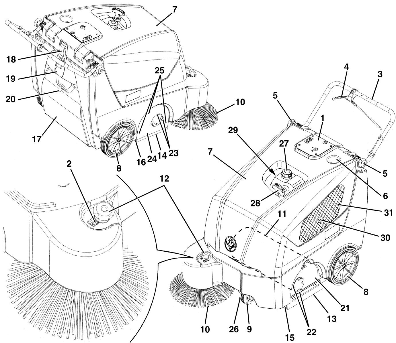
MACHINE DESCRIPTION
MACHINE STRUCTURE
- Control panel
- Lifted side broom fastener
- Handlebar
- Drive lever
- Handlebar adjusting knobs
- Can holder
- Hood
- Rear driving wheels on fixed axle
- Front steering wheel
- Side broom
- Main broom
- Side broom lifting and height adjusting knob
- Left side skirt
- Right side skirt
- Front skirt
- Rear skirt
- Debris container
- Debris container hook
-
Debris container handle
-
Manual filter shaker handle
- Main broom movable lid
- Main broom height left adjuster
- Main broom height right adjuster
- Main broom right lid
- Main broom right lid mounting screws
- Pedal brake on front wheel (optional)
- Fuel tank cap
- Engine pull-start cord handle
- Fuel tap and engine choke lever compartment
- Engine exhaust pipe
- Engine ventilation grid
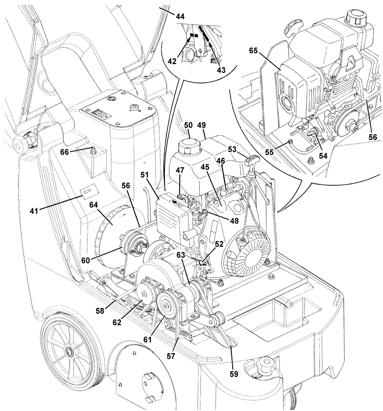
MACHINE STRUCTURE (Continues)
- Serial number plate/technical data/conformity certification
- Engine model
- Engine serial number
- Hood (open)
- Petrol engine
- Spark plug
- Choke lever
- Fuel tap
- Fuel tank
- Fuel tank cap
- Air filter
- Throttle lever (adjusted by the Manufacturer: do not tamper with it nor use it to change the engine speed!)
- Engine pull-start cord handle
- Engine oil filler/level check plug
- Engine oil drain plug
-
Engine belt
-
Main broom belt
- Driving belt
- Side broom belt
- Petrol engine drive pulley
- Main broom drive pulley
- Drive system drive pulley
- Side broom drive pulley
- Vacuum fan
- Engine silencer
- Hood safety switch
S311477
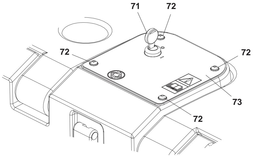
CONTROL PANEL
-
Ignition key:
-
Position "0": The machine is off and all functions are disabled
-
Position "I": The machine is on and all functions are enabled
-
Panel mounting screws
- Panel
S311478
ACCESSIONS/OPTIONS
In addition to the standard components, the machine can be equipped with the following accessories/options, according to the machine specific use:
- Main and side brooms with harder or softer bristles
- Antistatic polyester or polyester BIA C dust filter
- Front wheel with pedal brake
Skirts of various materials
For further information concerning the optional accessories, contact an authorised Retailer.
TECHNICAL DATA
| General | Values |
| Machine length | 1,070 mm |
| Machine width (without side brooms) | 667 mm |
| Machine height (with lowered handlebar) | 836 mm |
| Minimum/maximum handlebar height | 824/1,120 mm |
| Cleaning width (without side broom) | 500 mm |
| Cleaning width (with side broom) | 720 mm |
| Minimum distance from the ground (skirts not included) | 40 mm |
| Main broom size (diameter x length) | 265 mm x 500 mm |
| Side broom diameter | 420 mm |
| Main broom speed | 400 rpm |
| Side broom speed | 52 rpm |
| Front steering wheel | 125/37.5-50 mm |
| Rear driving wheel (diameter x width) | 250 x 50 mm |
| Machine total weight | 96 kg |
| Debris container capacity | 40 litres |
| Sound pressure level at workstation (ALpa) | 77 dB(A) |
| Vibration level at the operator's arms (*) | 3.3 m/s2 |
() Under normal working conditions, on a level asphalt surface.
() For other petrol engine data/values, see the relevant Manual.
| Performance | Values |
| Maximum forward speed | 4.4 km/h |
| Gradeability | 2% |
| Dust vacuuming and filtering | Values |
| Paper dust filter 5-10 μm | 2 m² |
| Main broom compartment vacuum | 18 mm H₂O |
| Petrol engine (*) | Values |
| Make | Honda |
| Model | GX 100 |
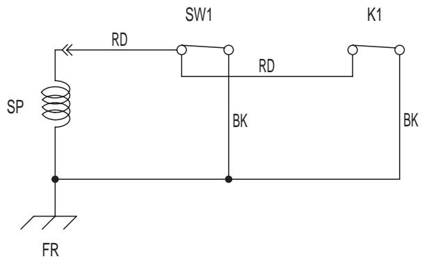
WIRING DIAGRAM
Key
| FR | Engine frame |
| K1 | Ignition switch |
| SP | Engine ignition coil |
| SW1 | Safety switch |
Colour code
| BK | Black |
| RD | Red |
USE

WARNING!
On some points of the machine there are some adhesive plates indicating:
DANGER
WARNING
- CAUTION
CONSULTATION
While reading this Manual, the operator must pay careful attention to the symbols shown on the plates.
Do not cover these plates for any reason and immediately replace them if they are damaged.
BEFORE STARTING THE MACHINE
- Make sure that the debris container (17) is properly closed before starting the machine.
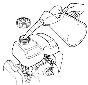
- If necessary, remove the cap (27) and refuel the machine.

CAUTION!
Do not fill the fuel tank beyond the upper limit mark (A, Fig. 1).
STARTING AND STOPPING THE MACHINE
Starting the machine
- Adjust the handlebar (3) with the knobs (5).
- Ensure that the side broom (10) is lifted.
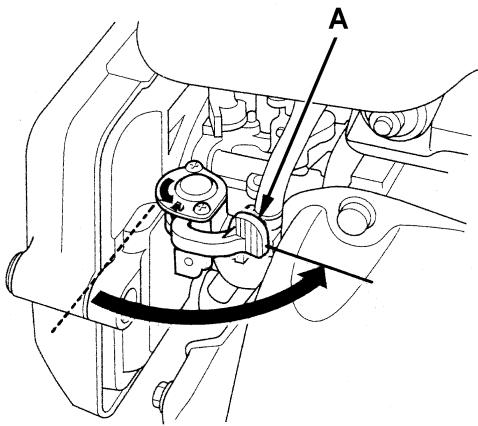
- Open the fuel tap (A, Fig. 2) by introducing the hand into the compartment (29) without opening the hood (7).
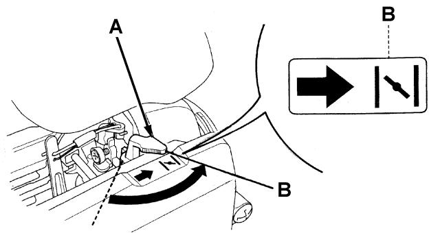
- Turn the engine choke lever (A, Fig. 3) to closed position (B) by introducing the hand into the compartment (29) without opening the hood (7).

NOTE
Do not close the choke lever if the engine is hot and if the air temperature is sufficiently high.
- Turn the ignition key (71) to "I".
- Pull slowly the engine pull-start cord handle (28) until a certain resistance is achieved; then pull suddenly and strongly and start the engine.

CAUTION!
Do not allow the handle (28) to return strongly but bring it back to its position slowly, to prevent the starting system from being damaged.

CAUTION!
When starting the engine with the handle (28) do not pull the drive lever (4).
S311480
Figure 1
S311481
Figure 2
Figure 3
S311482

WARNING!
The engine cannot be started with the handle (28) when the hood (7) is open. A safety system prevents the engine from starting.

NOTE
When the engine is running, the main broom turns, while the side broom does not move, if lifted.
- 5 seconds after the engine has been running, disengage the engine choke lever (A, Fig. 3) by introducing the hand into the compartment (29), without opening the hood (7).
- Release the pedal brake (26) (optional).
- Lower the side broom (10), then disengage the fastener (2) and lower the knob (12) (without turning it).

NOTE
The side broom (10) can be lifted and lowered even if it is turned on.
- Pull the drive lever (4) with care until the machine starts to move. The speed is proportional to the pressure applied to the drive lever (4).
Stopping the machine
- To stop the machine, release the drive lever (4) completely.
- To turn off the side broom (10) lift the knob (12) (without turning it), and then engage the fastener (2).
- To turn off the main broom (11) and the vacuum fan (64), turn the ignition key (71) to "0".
- Then close the fuel tap (48) in the compartment (29).
MACHINE OPERATION
- Avoid stopping for a long time with the machine in the same position and the brooms turning: this could create unwanted marks on the floor.
-
For machine proper operation, the dust filter must be as clean as possible. To clean the filter while sweeping, turn on the filter shaker according to the following procedure:
-
Pull the handle (20) outward to the end of stroke, then suddenly release it; the inner return spring thus strikes the dust filter frame and shakes it. Repeat this procedure several times.

NOTE
Repeat the filter shaking procedure at least every 10 minutes. This interval can change depending on the dustiness of the area to be cleaned.

NOTE
When the dust filter is clogged and/or the debris container is full, the machine cannot collect dust and debris anymore.

CAUTION!
Do not work on wet floors to prevent the dust filter from being damaged.
- The debris container (17) should be emptied after each working cycle and whenever it is full.

CAUTION!
The engine is equipped with a warning system to prevent damages to the engine itself in case the oil quantity in the carter is insufficient. Before the oil level goes below the safety limit, the warning system automatically stops the engine.
DEBRIS CONTAINER EMPTYING
- Stop the machine by releasing the drive lever (4).
- Turn the ignition key (61) to "0".
- Turn on the filter shaker with the handle (20).
- Disengage the debris container hook (18) by pulling its lower end.
- With the handle (19) remove the debris container (17) and empty it into an appropriate container.
- Install the debris container (17) and engage the hook (18).
- Restart the engine.
- The machine is ready to start working again.
AFTER USING THE MACHINE
After working, before leaving the machine, perform the following procedures.
- Clean the dust filter by using the manual filter shaker (20).
- Empty the debris container (17) (see the procedure in the previous paragraph).
- Lift the side broom with the knob (12).
- Remove the ignition key (71).
- Make sure that the machine cannot move independently.
- If equipped, press the pedal brake (26).
- Close the fuel tap (48) in the compartment (29).
PUSHING THE MACHINE
The machine can be pushed both with the ignition key (71) to "0" and to "1".
MACHINE LONG INACTIVITY
If the machine is not going to be used for more than 30 days, proceed as follows:
- Check that the machine storage area is dry and clean.
- Slightly lift the machine so that the skirts, the main broom and the wheels do not touch the ground.
- Handle the petrol engine as shown in the relevant Manual.
FIRST PERIOD OF USE
After the first period of use perform the following procedures:
- After the first 8 hours, check the machine fastening and connecting parts for proper tightening and check the visible parts for integrity and leakage.
- After the first 20 hours, or after the first month, change the engine oil (see the procedure in the Petrol Engine Manual).
MAINTENANCE
The lifespan of the machine and its maximum operating safety are ensured by correct and regular maintenance.
The following table provides the scheduled maintenance. The intervals shown may vary according to particular working conditions, which are to be defined by the person in charge of the maintenance.
All scheduled or extraordinary maintenance procedures must be performed by qualified personnel, or by an authorised Service Center.
This Manual describes only the easiest and most common maintenance procedures.
For other maintenance procedures shown in the Scheduled Maintenance Table, refer to the Service Manual that can be consulted at any Service Center.

WARNING!
To perform maintenance procedures, the machine must be off and, if necessary, the batteries must be disconnected.
Moreover, carefully read all the instructions in the Safety chapter before performing any maintenance procedure.
SCHEDULED MAINTENANCE TABLE
| Procedure | Upon deli-very | Running-in period (1) | Every 10 hours (1) | Every 50 hours (1) | Every 100 hours (1) | Every 200 hours (1) | Every 300 hours (1) | Every 2 years |
| Engine oil level check | (2) (7) | |||||||
| Engine air filter check | (2) (7) | |||||||
| Dust filter cleaning and integrity check | (2) | |||||||
| Side and main broom height check and adjustment | ||||||||
| Skirt height check and adjustment | ||||||||
| Hood safety switch operation check | ||||||||
| Filter shaker operation check | (3) | |||||||
| Engine air filter cleaning | (5) (7) | |||||||
| Driving belt tensioner adjustment | (2) | |||||||
| Driving belt visual inspection: engine, drive system, main broom, side broom | (3) | (3) | ||||||
| Engine oil change | (7) (10) | (4) (7) | ||||||
| Spark plug check/cleaning | (7) | |||||||
| Fuel tank and filter cleaning | (6) | |||||||
| Nut and screw tightening check | (9) | (3) | ||||||
| Engine speed check | (3) | |||||||
| Driving belt replacement: engine, drive system, main broom, side broom | (3) (8) | |||||||
| Engine air filter replacement | (5) (7) | |||||||
| Spark plug replacement | (4) (7) | |||||||
| Valve clearance check/adjustment | (6) | |||||||
| Engine combustion chamber cleaning | (6) | |||||||
| Fuel pipe check/replacement | (6) |
(1) To determine the maintenance intervals, note the working hours.
(2) Or before use.
(3) For the relevant procedure, see the Service Manual.
(4) Or every year.
(5) Or more often in dusty areas.
(6) Maintenance procedures to be performed by an authorised Honda Dealer, unless the operator has the service equipment and data, and is qualified to perform such procedures.
(7) For the relevant procedure, see the Petrol Engine Manual.
(8) If the person in charge for the maintenance considers it necessary.
(9) After the first 8 hours.
(10) The first time after 20 hours or after one month.
MAIN BROOM HEIGHT CHECK AND ADJUSTMENT

NOTE
Brooms with harder or softer bristles are available. This procedure is applicable to all types of brooms.
-
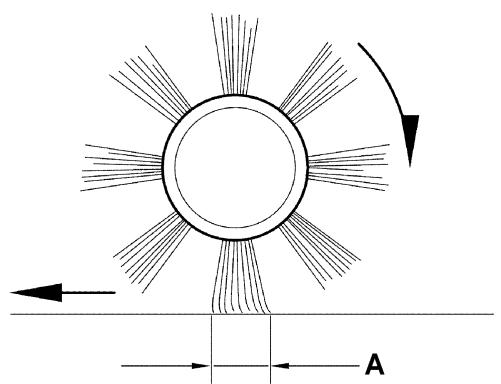
Check the main broom distance from the ground as shown below:
-
Drive the machine on a level floor.
Keep the machine stationary and turn on the main broom for a few seconds. - Stop the main broom, then move the machine and turn it off.
- Check that the main broom print (A, Fig. 4), along its length, is 2 to 4cm wide.
-
If the print (A, Fig. 4) is not within specifications, adjust the broom height as shown in step 2.
-
Make sure that the machine cannot move independently; if equipped, press the pedal brake (26).
- Turn the ignition key (71) to "0".
- Loosen the knobs (A, Fig. 5) on both sides of the machine.
- On both sides of the machine, loosen the knobs (A, Fig. 5) and move the main broom height variation indicator (B) as necessary, then tighten the knobs (A).

NOTE
The indicator (B, Fig. 5) must be in the same position on both sides of the machine; the maximum difference allowed to obtain the print (A, Fig. 4) shown in step 1 (2 - 4 cm wide) is two notches.
- Perform step 1 again to check that the main broom is at the correct distance from the ground.
- When the broom is too worn to be adjusted, replace it as shown in the next paragraph.

CAUTION!
If the main broom print is excessive (larger than 4cm ), the machine regular operation is affected and the moving or electrical parts can overheat, thus reducing machine life.
Pay careful attention when performing the above-mentioned checks, and always use the machine according to the indicated conditions.
0,8 - 1,6 inch
2÷ 4 cm
S311457
Figure 4
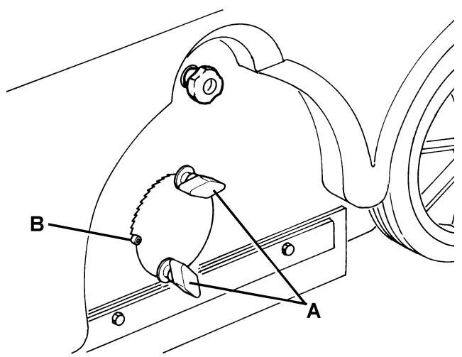
Figure 5
S311458
MAIN BROOM REPLACEMENT

CAUTION!
It is advisable to wear protective gloves when replacing the main broom because there can be sharp debris between the bristles.
- Drive the machine on a level floor and press the pedal brake (26), if equipped.
- Turn the ignition key (71) to "0".
- Loosen the knobs (A, Fig. 6) on both sides of the machine.
- Move the height variation indicators (B, Fig. 6) until the main broom is at the maximum distance from the ground. Tighten the knobs (A, Fig. 6).
- Open the hood (7).
- On the left side of the machine, loosen the knob (C, Fig. 6).
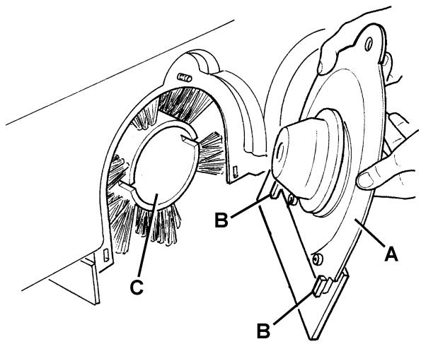
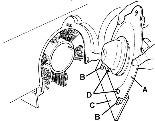
- Remove the main broom cover (A, Fig. 7) by pressing it downwards to disengage the fasteners (B).
- Remove the main broom (C, Fig. 7).
- Check that the drive hub (A, Fig. 8) is free from dirt or foreign materials (ropes, rags, etc.) accidentally rolled up.
- The new main broom must be installed with the bristles rows (A, Fig. 9) bent as shown in the figure.
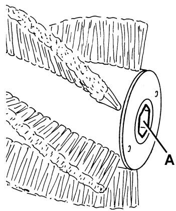
- Install the new main broom and ensure that the mesh (A, Fig. 10) correctly fits into the relevant drive hub (A, Fig. 8).
- Install the main broom cover (A, Fig. 7) by engaging the fasteners (B).
- Tighten the knob (C, Fig. 6).
- Adjust the main broom height as shown in the previous paragraph.
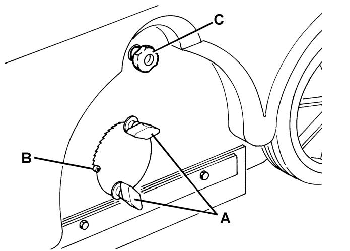
Figure 6
S311460
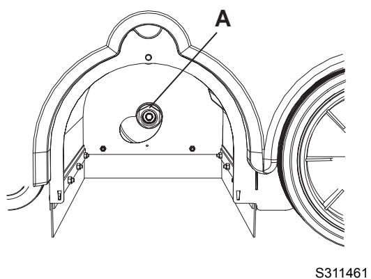
Figure 7
Figure 8
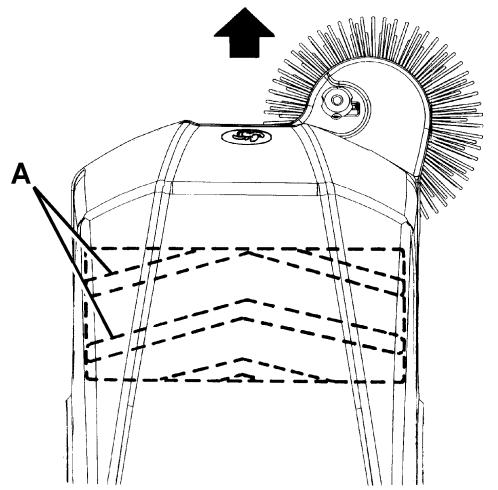
Figure 10
S311462
Figure 9
S311463
SIDE BROOM HEIGHT CHECK AND ADJUSTMENT

NOTE
Brooms with harder or softer bristles are available. This procedure is applicable to all types of brooms.
-
Check the side broom distance from the ground as shown below:
-
Drive the machine on a level floor and lower the side broom.
- Keep the machine stationary and turn on the side broom for a few seconds.
- Stop the side broom, then move the machine and turn it off.
-
Check that the side broom print is as shown in the figure (A, Fig. 9). If the print is not within the specifications, adjust the side broom height as shown in the following steps.
-
Turn the knob (B, Fig. 11) clockwise and counter-clockwise to adjust the side broom height.
- Perform step 1 again to check the proper adjustment of the side broom distance from the ground.
- When the broom is too worn to be adjusted, replace it as shown in the next paragraph.
SIDE BROOM REPLACEMENT

CAUTION!
It is advisable to wear protective gloves when replacing the main broom because there can be sharp debris between the bristles.
- Drive the machine on a level floor and press the pedal brake (26), if equipped.
- Turn the ignition key (71) to "0".
- Lay the hand inside the side broom and press the tabs (A, Fig. 12) inwards, then remove the broom (B) by disengaging it from the four pins (C).
- Install the new side broom by engaging it on the pins (C, Fig. 12) and on the tabs (A).
- Adjust the side broom height as shown in the previous paragraph.

Figure 11
S311464
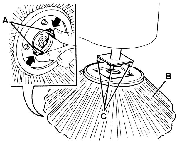
Figure 12
S311465
DUST FILTER CLEANING AND INTEGRITY CHECK

NOTE
Besides the standard paper filter, polyester filters are also available. The following procedure is applicable to each type of filter.
- Drive the machine on a level ground. Make sure that the machine cannot move independently; if equipped, press the pedal brake (26).
- Turn the ignition key (71) to "0".
- Disengage the debris container hook (18).
- Remove the debris container (17) with the handle (19).
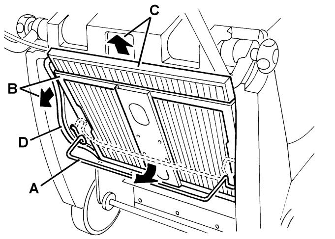
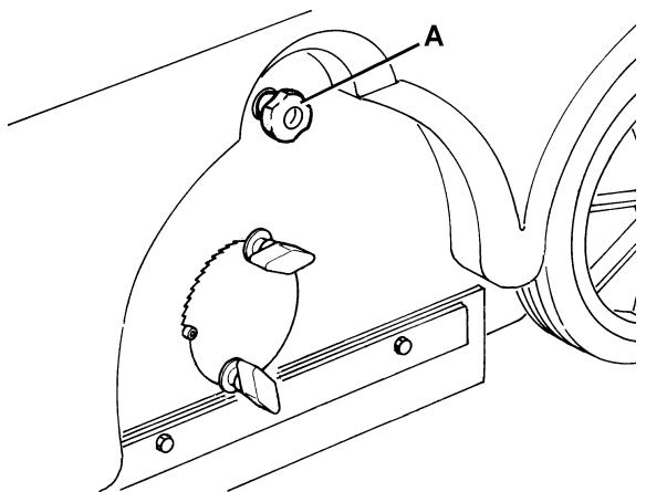
- Turn the handle (A, Fig. 13) upwards (90^ approximately) and let the filter frame (B) turn outward.
- Remove the dust filter (C, Fig. 13).
- In an outdoor area, clean the dust filter by shaking it on a level and clean surface, tapping the side (A, Fig. 14) opposite to the wire gauze (B).
- Complete the cleaning procedure by using compressed air (C, Fig. 14) at maximum 6 Bar, blowing only from the side protected by the wire gauze (B).
Moreover, according to the filter type, observe the following cautions:
- Paper filter (standard): Do not use water or detergents to clean it, otherwise it can be damaged.
-
Polyester filter (optional): For a better cleaning, it is allowed to wash the filter with water and non-lathering detergents. This provides better quality cleaning but reduces the life of the filter, which will have to be replaced more frequently. The use of inadequate detergents can damage the filter.
-
Check the filter body for tears.
- If necessary, clean the filter compartment rubber gasket (D, Fig. 13) along its perimeter and check it for integrity. If necessary, replace it.
- Assemble the components in the reverse order of disassembly, and note the following:
Install the filter (C, Fig. 13) with the wire gauze (B, Fig. 14) turned towards the machine front side.
S311466
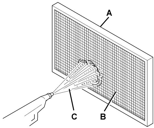
Figure 13
S311467
Figure 14
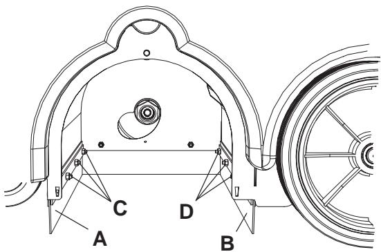
SKIRT HEIGHT CHECK AND ADJUSTMENT
- Drive the machine on a level floor that is suitable for checking the skirt height. Make sure that the machine cannot move independently; if equipped, press the pedal brake (26).
- Turn the ignition key (71) to "0".
Side skirt check
- Check the side skirts (13 and 14) for integrity.
Replace the skirts when they have cuts (A, Fig. 15) larger than 20 ~mm or cracks/tears (B) larger than 10 ~mm (for skirt replacement, refer to the Service Manual). - Check that distance from the ground of the side skirts (13 and 14) is within 0 - 3mm (A, Fig. 16). If necessary, adjust the skirt height according to the following procedure.
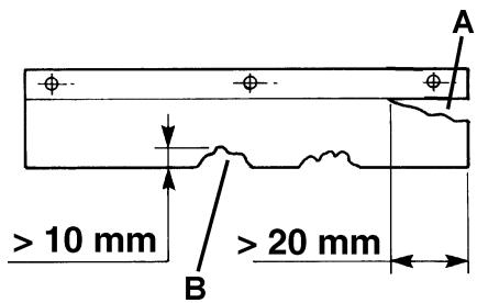
Figure 15
S311468
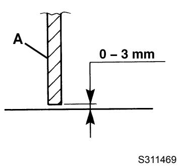
Figure 16
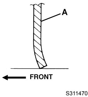
Figure 17
Left skirt
- Open the hood (7), loosen the knob (A, Fig. 18) and remove the main broom left cover (A, Fig. 19), by pressing it downwards to disengage the fasteners (B).
- Adjust the height of the left skirt (C, Fig. 19) by using the slots (D).
- Assemble the components by performing steps 5 to 6 in the reverse order.
Right skirt
- Remove the main broom as shown in the relevant paragraph.
- Remove the main broom belt (57) from the pulley (61); for an easier removal, turn the pulley (61) by manually operating on the fan (64).
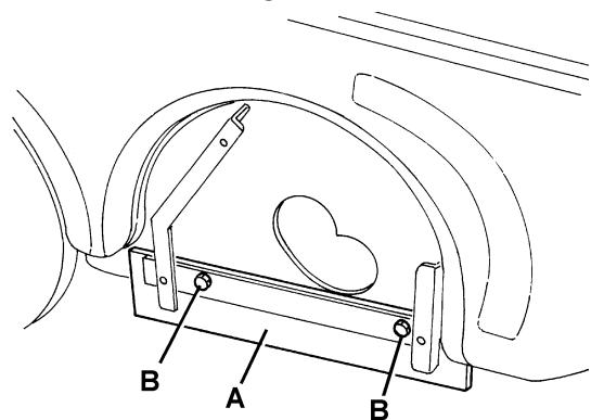
- Remove the screws (25) and the right cover (24) together with the belt (57).
- Adjust the height of the skirt (A, Fig. 20) by using the slots (B).
- Assemble the components by performing steps 8, 9 and 10 in the reverse order.
Front and rear skirt check
- Remove the main broom as shown in the relevant paragraph.
- Check the front (A, Fig. 21) and rear skirts (B) for integrity.
- Replace the skirts when they have cuts (A, Fig. 15) larger than 20mm or cracks/tears (B) larger than 10mm (for skirt replacement, refer to the Service Manual).
-
Check that:
-
The front skirt (A, Fig. 17) slightly touches the floor (as shown in the figure).
-
The distance from the ground of the rear skirt (A, Fig. 16) is within 0 - 3mm (as shown in the figure).
-
If necessary, adjust the skirt height by using the slots on the screws (C and D, Fig. 19).
- Assemble the components in the reverse order of disassembly.
HOOD SAFETY SWITCH OPERATION CHECK
While the engine is running, slightly open the hood (7) and check that the engine stops immediately.
If the engine keeps running when the hood (7) is open, contact an authorised Service Center or Retailer.
S311471
Figure 18
S311472
Figure 19
S311473
Figure 20
Figure 21
S311474
TROUBLESHOOTING
| Trouble | Possible cause | Remedy |
| The engine does not start when pulling the handle. | The ignition key is not turned to "I". | Turn the ignition key to "I". |
| The engine oil level is low. | Add engine oil. (1) | |
| The fuel tap is closed. | Open the fuel tap. | |
| The fuel tank is empty. | Refuel. | |
| The hood is not properly closed. | Close the hood properly. | |
| The fuel does not reach the carburettor. | Check if the fuel reaches the carburettor. (1) | |
| The spark plug does not produce a spark. | Clean/replace the spark plug. (1) | |
| The engine stops during operation. | The engine oil level is low. | Add engine oil. (1) |
| The fuel tank is empty. | Refuel. | |
| The side broom does not operate. | The side broom is not lowered. | Lower the side broom. |
| The side broom belt or belt tensioner is not efficient. | Contact an authorised Nilfisk-Advance Service Center. | |
| When pulling the drive lever, the machine does not move, or it moves slowly. | The pedal brake (optional) is engaged. | Release the pedal brake (optional). |
| The driving belt tensioner is not operating. | Contact an authorised Nilfisk-Advance Service Center. | |
| The driving belt is not efficient. | Contact an authorised Nilfisk-Advance Service Center. |
(1) For the relevant procedure, see the Petrol Engine Manual.
For further information, refer to the Service Manual, available at any Nilfisk-Advance Service Center.
SCRAPPING
Have the machine scrapped by a qualified scrapper.
Before scrapping the machine, remove and separate the following materials, which must be disposed of properly according to the Law in force:
Polyester dust filter
- Main and side brooms
Engine oil - Plastic hoses and components
- Electrical and electronic components (*)
(*) Refer to the nearest Nilfisk-Advance Center especially when scrapping electrical and electronic components.
INHOUDSOPGAVE
INLEIDING 2
DOEL EN INHOUD VAN DEZE HANDLEIDING 2
BETREFENDE PERSONEN 2
OPBERGEN VAN DE HANDLEIDING 2
CONFORMITEITSVERKLARING 2
IDENTIFICATIEGEGEVENS 2
ANDERE GEBRUKERSHANDLEIDENGIN 2
VERVANGINGSONDERDELEN EN ONDERHOUD 3
MODIFICATIES EN VERBETERINGEN 3
BEDRIJFSCAPACITEIT 3
ALGEMENE OPMERKINGEN 3
VERPAKKING VERWIJDEREN/AFLEVERING 3
VEILIGHEID 3
GEBRUIKTE SYMBOLEN 3
ALGEMENE INSTRUCTIONS 4
BESCHRIJVING VAN DE MACHINE 6
BOUW VAN DE MACHINE 6
BEDIENINGSPANEEL 8
ACCESSIONS / OPTIES 8
TECHNISCHE EIGENSCHAPPEN 9
ELEKTRISCH SCHEMA 9
GEBRUIK 10
VOOR HET STARTEN 10
DE MACHINE STARTEN EN STOPPEN 10
MACHINE IN BEDRIJF 11
DE AFVALCONTAINER LEGEN 12
NA GEBRUIK VAN DE MACHINE 12
MAXIMALE VOORWAARTSE BEWEGING 12
LANGE PERIODE VAN STILLSTAND 12
EERSTE GEBRUIKSPERIODE 12
ONDERHOUD 12
ONDERHOUDSSCHEMA 13
DE HOOGTE VAN DE HOOFDBORSTEL CONTROLLEREN EN AFSTellen 14
DE HOOFDBORSTELVERVANGEN 15
DE HOOGTE VAN DE ZIJBORSTEL CONTROLLEREN EN AFSTellen 16
DE ZIJBORSTEL VERVANGEN 16
REINIGING EN CONTOLE OP INTEGRITEIT VAN HET STOFFILTER 17
DE HOOGTE VAN DE FLAPS CONTROLLEREN EN AFSTellen 18
CONTROLE VAN DE WERKING VAN DE BEVEILIGINGSSCHAKELAAR VOOR OPENING VAN DE MOTORKAP 19
STORINGEN LOKALISEREN 20
VERWIJDERING 20
INLEIDING

OPMERKING
GEVAAR
LETOP
WAARSCHUWING
- ADVIES


- INHALTSVERZEICHNIS
- EINLEITUNG 2
- CONSERVATION DU MANUEL
- STRUCTURE DE LA MACHINE
- STRUCTURE DE LA MACHINE (suite)
- ACCESSIONS / OPTIONS
- DEPLACEMENT PAR POUSSEE DE LA MACHINE
- REEMPLACEMENT DU BALAI CENTRAL
- AVERTISSEMENT!
- REEMPLACEMENT DU BALAI LATERAL
- USE 10
- MAINTENANCE 12
- TROUBLESHOOTING 20
- SCRAPPING 20
- INTRODUCTION
- NOTE
- MANUAL PURPOSE AND CONTENTS
- TARGET
- HOW TO KEEP THIS MANUAL
- DECLARATION OF CONFORMITY
- IDENTIFICATION DATA
- OTHER REFERENCE MANUALS
- SPARE PARTS AND MAINTENANCE
- CHANGES AND IMPROVEMENTS
- CONVENTIONS
- UNPACKING/DELIVERY
- SAFETY
- SYMBOLS
- DANGER!
- WARNING!
- CAUTION!
- CONSULTATION
- GENERAL INSTRUCTIONS
- MACHINE DESCRIPTION
- MACHINE STRUCTURE
- MACHINE STRUCTURE (Continues)
- CONTROL PANEL
- ACCESSIONS/OPTIONS
- USE
- BEFORE STARTING THE MACHINE
- STARTING AND STOPPING THE MACHINE
- Starting the machine
- Stopping the machine
- MACHINE OPERATION
- DEBRIS CONTAINER EMPTYING
- AFTER USING THE MACHINE
- PUSHING THE MACHINE
- MACHINE LONG INACTIVITY
- FIRST PERIOD OF USE
- MAINTENANCE
- MAIN BROOM HEIGHT CHECK AND ADJUSTMENT
- MAIN BROOM REPLACEMENT
- SIDE BROOM HEIGHT CHECK AND ADJUSTMENT
- SIDE BROOM REPLACEMENT
- DUST FILTER CLEANING AND INTEGRITY CHECK
- SKIRT HEIGHT CHECK AND ADJUSTMENT
- Side skirt check
- Left skirt
- Right skirt
- Front and rear skirt check
- HOOD SAFETY SWITCH OPERATION CHECK
- SCRAPPING
- INHOUDSOPGAVE
- INLEIDING 2
- VERPAKKING VERWIJDEREN/AFLEVERING 3
- VEILIGHEID 3
- BESCHRIJVING VAN DE MACHINE 6
- GEBRUIK 10
- ONDERHOUD 12
- STORINGEN LOKALISEREN 20
- VERWIJDERING 20
- INLEIDING
- OPMERKING
Brand : NILFISK
Model : SW 700S P
Category : Sweeper