
BR 651 - Scrubber NILFISK - Free user manual and instructions
Find the device manual for free BR 651 NILFISK in PDF.

| Product type | Scrubber-dryer for smooth floors |
| Brand and model | NILFISK BR 651 |
| Cleaning width | 660 mm (with disc brushes) |
| Squeegee width | 830 mm |
| Solution tank capacity | 75 liters |
| Recovery tank capacity | 75 liters |
| Working speed | 0 to 6 km/h (variable) |
| Maximum climbable slope | 16 % |
| Suction motor | 500 W |
| Traction motor | 600 W |
| Power supply | 24 V DC (lead-acid or gel battery, 240 Ah or 180 Ah) |
| Sound pressure (operator) | 67.5 dB(A) |
| Dimensions (L × W × H) | 1450 × 681.5 × 1250 mm (with disc head, without squeegee) |
| Empty weight (without batteries) | 140 kg |
| Maximum loaded weight | 385 to 470 kg (depending on batteries and full tanks) |
| Brush type | Discs (2 × diam. 330 mm) or cylindrical |
| Disc brush rotation speed | 190 rpm |
| Brush pressure | 30 kg (normal), 50 kg (extra pressure) |
| Safety | Emergency stop, electromagnetic brake, seat micro-switch, speed reduction when turning |
| Maintenance | Daily cleaning of squeegee, brushes, tanks, suction grille; battery charging; weekly checks |
| Repairability | Original Nilfisk parts, maintenance manual available, authorized after-sales support |
Frequently Asked Questions - BR 651 NILFISK
User questions about BR 651 NILFISK
0 question about this device. Answer the ones you know or ask your own.
Ask a new question about this device
Download the instructions for your Scrubber in PDF format for free! Find your manual BR 651 - NILFISK and take your electronic device back in hand. On this page are published all the documents necessary for the use of your device. BR 651 by NILFISK.
USER MANUAL BR 651 NILFISK
The undersigned certify that the above mentioned model is produced in accordance with the following directives and standards.
Authorized signatory: Franco Mazzini, General Mgr
Date:
Signature:
B
S311212
C
S311377
D
S311214
E
S311215
F
S311216
EINLEITUNG 2
M1: Motor Bürste links
CONSERVATION DU MANUEL 2
ATTESTATION DE CONFORMITE 2
DONNEES D'IDENTIFICATION 2
ACCESSIONS/OPTIONS 8
UTILISATION 9
CONTROLE / PREPARATION DES BATTERIES SUR UNE MACHINE NEUVE 9
INSTALLATION DES BATTERIES ET CONFIGURATION DU TYPE DE BATTERIES (WET OU GEL) .... 10
AVANT LA MISE EN MARCHE 10
MISE EN MARCHE ET ARRET DE LA MACHINE 12
MACHINE AU TRAVAIL 12
VIDANGE DES RESERVOIRS 13
APRES L'UTILISATION DE LA MACHINE 14
MOUVEMENT PAR POUSSEE/REMORQUAGE DE LA MACHINE 14
INACTIVITE PROLONGEE DE LA MACHINE 14
PREMIERE PERIODE D'UTILISATION 14
ENTRETIEN 14
PLAN D'ENTRETIEN PROGRAMME 15
CONTROLE DES HEURES DE TRAVAIL DE LA MACHINE 15
NETTOYAGE DE L'EMBOUCHURE 15
CONTROLE ET REMPLACEMENT DES LAMELLES EN CAOUTCHOUC DE L'EMBOUCHURE 16
NETTOYAGE DES BROSSES OU DES BROSSES CYLINDRIQUES 16
NETTOYAGE DES RESERVOIRS ET DE LA GRILLE D'ASPIRATION AVEC FLOTTEUR 16
NETTOYAGE DU RESERVOIR DU DETERGENT (Optionnel) 16
VIDANGE DU SYSTEME EDS - SYSTEME D'ALIMENTATION DU DETERGENT (Optionnel) 17
CONTROLE ET REMPLACEMENT DES VOLETS LATERAUX 17
NETTOYAGE DU FILTRE DE LA SOLUTION 18
CHARGEMENT DES BATTERIES 18
CONTROLE/REPLACEMENT DES FUSIBLES 19
DEPOSE/REPOSE DE LA TETE PORTE-BROSSSES/PLATEAUX SUPPORT DISQUE
OU DE LA TETE PORTE-BROSSES CYLINDRIQUES 19
FONCTIONS DE SECURITE 19
BOUTON-POUSSOIR D'ARRET D'URGENCE 19
REDUCTION DE LA VITESSE EN VIRAGE 19
MICROINTERRUPTEUR DU SIEGE DE CONDUITE 19
FREIN ELECTROMAGNETIQUE 19
DEPISTAGE DES PANNES 20
MISE EN DECHARGE 20
INTRODUCTION
BUT ET CONTENU DU MANUEL
CONSERVATION DU MANUEL
MANUAL PURPOSE AND CONTENTS 2
TARGET 2
HOW TO KEEP THIS MANUAL 2
CONFORMITY CERTIFICATE 2
IDENTIFICATION DATA 2
OTHER REFERENCE MANUALS 2
SPARE PARTS AND MAINTENANCE 2
CHANGES AND IMPROVEMENTS 2
SAFETY 2
SYMBOLS 3
GENERAL INSTRUCTIONS 3
UNPACKING/DELIVERY 4
MACHINE DESCRIPTION 5
ACCESSIONS/OPTIONS 8
USE 9
BATTERY CHECK/SETTING ON A NEW MACHINE 9
BATTERY INSTALLATION AND BATTERY TYPE SETTING (WET OR GEL) 10
BEFORE START-UP 10
MACHINE START AND STOP 12
AFTER USING THE MACHINE 14
PUSHING/TOWING THE MACHINE 14
MACHINE LONG INACTIVITY 14
FIRST PERIOD OF USE 14
MAINTENANCE 14
SCHEDULED MAINTENANCE TABLE 15
MACHINE WORKING HOUR CHECK 15
SQUEEGEE CLEANING 15
SQUEEGEE BLADE CHECK AND REPLACEMENT 16
BRUSH/CYLINDRICAL BRUSH CLEANING 16
TANK AND VACUUM GRID WITH FLOAT CLEANING 16
DETERGENT TANK CLEANING (Optional) 16
EDS-ECO DOSAGE SOLUTION DRAINING (Optional) 17
SIDE SKIRT CHECK AND REPLACEMENT 17
SOLUTION FILTER CLEANING 18
BATTERY CHARGING 18
FUSE CHECK/REPLACEMENT 19
BRUSH/PAD-HOLDER DECK OR CYLINDRICAL BRUSH DECK DISASSEMBLY/ASSEMBLY 19
SAFETY FUNCTIONS 19
EMERGENCY STOP BUTTON 19
SPEED REDUCTION 19
DRIVER'S SEAT MICROSWITCH 19
ELECTROMAGNETIC BRAKE 19
TROUBLESHOOTING 20
SCRAPPING 20
INTRODUCTION
MANUAL PURPOSE AND CONTENTS
The purpose of this Manual is to provide the operator with all necessary information to use the machine properly, in a safe and autonomous way. It contains information about technical data, safety, operation, storage, maintenance, spare parts and disposal.
Before carrying out any procedure on the machine, the operators and qualified technicians must read this Manual carefully. Contact Nilfisk-Advance in case of doubts concerning the interpretation of the instructions and for any further information.
TARGET
This Manual is intended for operators and technicians qualified to perform the machine maintenance.
The operators must not carry out procedures reserved for qualified technicians. Nilfisk-Advance will not be answerable for damages coming from the non-observation of this prohibition.
HOW TO KEEP THIS MANUAL
The User Manual must be kept near the machine, inside an adequate case, away from liquids and other substances that can cause damage to it.
CONFORMITY CERTIFICATE
Figure A shows the documentation certifying the scrubber-dryer conformity with the law in force.

NOTE
Two copies of the original EC Declaration of Conformity are provided together with the machine documentation.
IDENTIFICATION DATA
The machine serial number and model are shown on the plate (30, Fig. C) on the steering column.
The machine model year is written in the EC Declaration of Conformity and it is also indicated by the first two figures of the machine serial number.
This information is useful when requiring machine spare parts. Use the following table to write down the machine identification data.
MACHINE model
MACHINE serial number
OTHER REFERENCE MANUALS
Electronic Battery Charger Manual (if equipped), to be considered as integral part of this Manual Moreover, the following Manuals are available:
Service Manual (that can be consulted at Nilfisk-Advance Service Centers)
- Spare Parts List (supplied with the machine)
SPARE PARTS AND MAINTENANCE
All necessary operating, maintenance and repair procedures must be carried out by qualified personnel or by Nilfisk-Advance Service Centers. Only original spare parts and accessories must be used.
Contact Nilfisk-Advance for service or to order spare parts and accessories, specifying the machine model and serial number.
CHANGES AND IMPROVEMENTS
Nilfisk-Advance constantly improves its products and reserves the right to make changes and improvements at its discretion without being obliged to apply such benefits to the machines that were previously sold.
Any change and/or addition of accessories must be approved and performed by Nilfisk-Advance.
SAFETY
The following symbols indicate potentially dangerous situations. Always read this information carefully and take all necessary precautions to safeguard people and property.
The operator's cooperation is essential in order to prevent injury. No accident prevention program is effective without the total cooperation of the person responsible for the machine operation. Most of the accidents that may occur in a factory, while working or moving around, are caused by failure to comply with the simplest rules for exercising prudence. A careful and prudent operator is the best guarantee against accidents and is essential for successful completion of any prevention program.
SYMBOLS

DANGER!
It indicates a dangerous situation with risk of death for the operator.

WARNING!
It indicates a potential risk of injury for people or damage to objects.

CAUTION!
It indicates a caution related to important or useful functions.
Pay careful attention to the paragraphs marked by this symbol.

NOTE
It indicates a remark related to important or useful functions.

CONSULTATION
It indicates the necessity to refer to the User Manual before performing any procedure.
GENERAL INSTRUCTIONS
Specific warnings and cautions to inform about potential damages to people and machine are shown below.

DANGER!
- Disconnect the batteries before performing any maintenance/repair procedure.
- This machine must be used by properly trained and authorised personnel only. Children or disabled people cannot use this machine.
- Keep the battery far from sparks, flames and incandescent material. During normal operation, explosive gases are released.
- Do not wear jewels when working near electrical components.
- Do not work under the lifted machine without supporting it with safety stands.
- Do not operate the machine near toxic, dangerous, flammable and/or explosive powders, liquids or vapours.
- Battery charging produces highly explosive hydrogen gas. Keep the tank assembly open during battery charging and perform this procedure in well-ventilated areas and away from naked flames.

WARNING!
- Carefully read all the instructions before carrying out any maintenance/repair procedure.
Before using the external battery charger, ensure that frequency and voltage, indicated on the machine serial number plate, match the mains voltage. - To reduce the risk of fire, electric shock, or injury, do not leave the machine unattended when it is plugged in. Unplug the machine from the outlet when not in use and before servicing.
- To avoid electric shock, do not expose to rain. Store the machine indoors.
- Do not allow to be used as a toy. Close attention is necessary when used near children.
- Use only as shown in this Manual. Only Nilfisk-Advance recommended accessories must be used.
- Do not use with damaged battery charger cable or plug. If the machine is not working as it should, has been damaged, left outdoors or dropped into water, return it to the Service Centre.
- Do not pull or carry the machine by the battery charger cable and never use the battery charger cable as a handle. Do not close a door on the battery charger cable, or pull the battery charger cable around sharp edges or corners. Do not run the machine on the battery charger cable. Keep the battery charger cable away from heated surfaces.
Take all necessary precautions to prevent hair, jewels and loose clothes from being caught by the machine moving parts. - Do not smoke while charging the batteries.
- Do not leave the machine unattended without being sure that it cannot move independently.
- Do not use the machine on slopes with a gradient exceeding the specifications.
- Do not wash the machine with direct or pressurised water jets, or with corrosive substances.
- Do not use the machine in particularly dusty areas.
While using this machine, take care not to cause damage to other people, especially children. - Do not put any can containing fluids on the machine.
- The storage temperature must be between 0^ and +40^ .
- The machine working temperature must be between 0^ and +40^ .
The humidity must be between 30% and 95% .
Always protect the machine against the sun, rain and bad weather, both under operation and inactivity condition.
- Do not use the machine as a means of transport.
- Do not use the machine on slopes with an inclination higher than 16% .
- Do not allow the brushes to operate while the machine is stationary to avoid damaging the floor.
In case of fire, use a powder fire extinguisher, not a water one.
- Do not bump into shelves or scaffoldings, especially where there is a risk of falling objects.
- Do not tamper with the machine safety guards and follow the ordinary maintenance instructions scrupulously.
- Do not remove or modify the plates affixed to the machine.
In case of machine malfunctions ensure that these are not caused by a lack of maintenance. Otherwise, request assistance from the authorised personnel or from an authorised Service Center.
- If parts must be replaced, require ORIGINAL spare parts from a Dealer or Authorised Retailer.
- To ensure proper and safe operation of the machine, have the scheduled maintenance, detailed in the relevant chapter of this Manual, performed by the authorised personnel or an authorised Service Centre
- The machine must be disposed of properly, because of the presence of toxic-harmful materials (batteries, etc.), which are subject to standards that require disposal in special centres (see Scrapping chapter).
- Do not allow any object to enter into the openings. Do not use the machine if the openings are clogged. Always keep the openings free from dust, hairs and any other foreign material which could reduce the air flow.
- This machine cannot be used on roads or public streets.
- Pay attention during machine transport, when temperature is below freezing point, because the water in the recovery tank or in the hoses could freeze and seriously damage the machine.
- Use only brushes and pads supplied with the machine or specified in this Manual. Using other brushes or pads could reduce safety.
- When WET batteries are installed on the machine, do not tilt the machine for more than 30^ from the horizontal plane to prevent the highly corrosive acid from leaking out of the batteries. If the machine must be tilted to perform any maintenance procedures, remove the batteries.
UNPACKING/DELIVERY
To unpack the machine, carefully follow the instructions on the packing.
When the machine is delivered, check that the packing and the machine were not damaged during transportation. In case of visible damages, keep the packing and have it checked by the Carrier that delivered it. Call the Carrier immediately to fill in a damage claim.
Check that the machine is equipped with the following features.
-
Technical documents:
-
Scrubber-dryer User Manual
Electronic Battery Charger Manual (if equipped) -
Scrubber-dryer Spare Parts List
-
No. 1 connector for battery charger (for machines without on board battery charger)
-
No. 2 lamellar fuses
- No. 5 shims for 6V battery housing
- One 2 mm-key for socket screws
MACHINE DESCRIPTION
This scrubber-dryer is used to clean (scrubbing and drying) smooth and solid floors, in civil or industrial environment, under safe operation conditions by a qualified operator. The scrubber-dryer cannot be used for fitted carpet and carpet cleaning.
CONVENTIONS
Forward, backward, front, rear, left or right are intended with reference to the operator's position, that is to say on the driver's seat (25, Fig. C).
DESCRIPTION
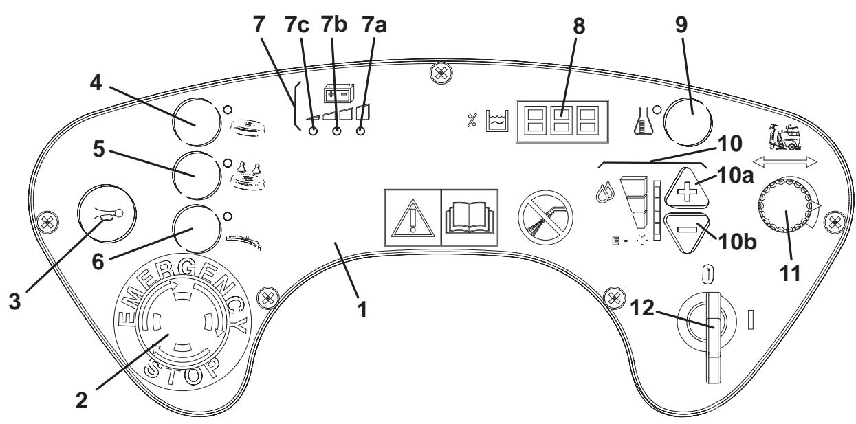
Control panel
(See Fig. B)
- Control panel
- Emergency stop button
- Horn
- Brush/pad-holder deck and squeezegee lifting/lowering switch
- Brush/pad-holder extra pressure switch (disabled when the cylindrical brush deck is installed)
- Squeezegee lifting/lowering and vacuum ON/OFF switch
- Battery charge indicator
7a. Green warning light (ON: charged batteries)
7b. Yellow warning light (ON: nearly discharged batteries)
7c. Red warning light (ON: discharged batteries) -
Hour counter and solution or washing water level display:
-
When the machine is started, it displays for a few seconds the number of working hours which have been performed.
While using the machine, it displays the solution or washing water level in the tank (measured in percentage terms, compared with the full tank). When the level is below 20% , the display starts blinking.
The display could indicate "000%" even if the tank is not completely empty, thus allowing to complete the cleaning cycle; in any case, it is recommended to check the actual washing water flow supplied to the brushes.
- Detergent flow control switch (optional)
- Washing water control switches
10a. Flow increase switch
10b. Flow decrease switch - Maximum speed adjuster (enabled only when the brushes are operating)
- Ignition key
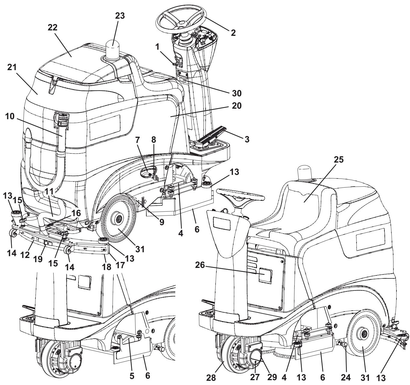
Outside view
(See Fig. C)
- Steering wheel inclination control lever
- Steering wheel
- Forward/reverse gear pedal
- Brush/pad-holder deck
- Cylindrical brush deck
- Side skirts
- Battery charger cable housing
- Cable with battery charger plug (optional)
- Filter for:
Solution
- Washing water (optional)
- Recovery water drain hose
- Squeezee vacuum hose
- Squeegee
- Bumper wheels
- Squeegee support wheels
- Squeegee mounting handwheels
- Squeegee balance adjusting knob
- Front squeezegee blade
- Rear squeezegee blade
- Squeegee rear blade fastening hook
- Solution or washing water tank (according to the system equipped)
- Recovery water tank
- Recovery water tank cover
- Flashing light (optional)
- Solution or washing water drain tap (according to the system equipped)
- Seat
- Battery charger (optional)
- Electromagnetic brake
- Front steering, driving and braking wheel
- Electromagnetic brake unlock screws
- Serial number plate/technical data/EC certification
- Rear wheels
View under tank covers (See Fig. 1)
- Recovery water tank cover
- Recovery water tank cover gasket
- Detergent pump (optional)
- Recovery water vacuum duct
- Vacuum grid with automatic shut-off float
- Float
- Grid fasteners
- Solution or washing water inlet opening
- Detergent tank (optional)
- Detergent tank filler plug (optional)
- Detergent tank handle (optional)
- Detergent supply hose (optional)
- Solution or washing water tank cap
- Cover stand
- Recovery water tank
- Tank for:
solution (machine not equipped with EDS-ECO Dosage Solution)
- washing water (machine equipped with EDS-ECO Dosage Solution)
View under tank assembly (See Fig. J)
- Tank assembly
- Batteries
- Battery case
- Battery connector
- Battery caps
- Battery connection diagrams
- Detergent supply hose union (optional)
- Detergent tank (optional)
- Detergent pump (optional)
Brush/pad-holder deck and cylindrical brush deck view (See Fig. K)
- Brush/pad-holder deck
- Brush/pad-holder motors
- Brush/pad-holder deck or cylindrical brush deck connector
- Solution supply hose
- Deck mounting knob
- Deck cotter pins
- Deck support
- Brush
- Pad-holder
- Pad
- Cylindrical brush deck connector
- Connector protection cover
- Cylindrical brush deck
- Cylindrical brush motors
- Brush/pad-holder deck side skirt
- Cylindrical brush deck side skirt
- Skirt upper mounting knob
- Skirt lower mounting knob
- Cylindrical brush
- Cylindrical brush lids
- Lid mounting knobs
- Cylindrical brush debris container
- Debris container handle
TECHNICAL DATA
| General technical data | |||
| Description | BR 601 | BR 651 | BR 751/BR 751C |
| Cleaning width | 610 mm | 660 mm | 740 mm |
| Squeezeeep width | 830 mm | 860 mm | |
| Solution or washing water tank capacity | 75 litres | ||
| Recovery water tank capacity | 75 litres | ||
| Rear wheel diameter | 300 mm | ||
| Wheel specific pressure on the ground | Less than 1.0 N/mm2 | ||
| Front steering, driving and braking wheel diameter | 250 mm | ||
| Vacuum system motor power | 500 W | ||
| Drive system motor power | 600 W | ||
| Drive speed (variable) | 0 to 6 km/h | ||
| Gradeability | 16% | ||
| Sound pressure level at workstation | 67.5 dB(A) | ||
| Vibration level at the operator's arms (*) | 0.23 – 7.5 m/s2 | ||
| Vibration level at the operator's body (*) | Less than 1.2 m/s2 | ||
| Batteries | 24 V battery box, 240 Ah/5 h (WET) 240 Ah C5 | ||
| 24 V battery box, 240 Ah/5 h (GEL) (optional) 240 Ah C5 | |||
| 4 6 V batteries, 180 Ah/5 h (WET) 180 Ah C5 | |||
| 4 6 V batteries, 180 Ah/5 h (GEL) (optional) 180 Ah C5 | |||
| Battery compartment size | 24 V battery box: 355 x 606 x 370 mm | ||
| 4 6 V batteries, with case: 530 x 380 x 300 mm | |||
| Vacuum system capacity | 1,800 mmH2O | ||
| Machine height | 1,250 mm | ||
| Machine maximum length | 1,450 mm | ||
| Machine width without squeezegee | 658 mm | 681.5 mm | 758 mm |
| Technical data for machines with brush/pad-holder deck | |||
| Description | BR 601 | BR 651 | BR 751 |
| Brush diameter | 305 mm | 330 mm | 370 mm |
| Weight without batteries and with empty tanks | 140 kg | ||
| Maximum weight with batteries and full tanks | 385/470 kg | ||
| Brush/pad-holder motor power | 400 W | ||
| Brush/pad-holder rotation speed | 190 rpm | ||
| Brush/pad-holder pressure with extra-pressure function turned off | 30 kg | ||
| Brush/pad-holder pressure with extra-pressure function turned on | 50 kg | ||
| Technical data for machines with cylindrical brush deck | |||
| Description | BR 751C | ||
| Cylindrical brush size (diameter x length) | 145 x 690 mm | ||
| Weight without batteries and with empty tanks | 140 kg | ||
| Maximum weight with batteries and full tanks | 385/470 kg | ||
| Cylindrical brush motor power | 600 W | ||
| Cylindrical brush rotation speed | 748 rpm | ||
| Cylindrical brush pressure | 33.4 kg | ||
(*) Under normal working conditions, on a level asphalt surface.
WIRING DIAGRAM
(See Fig. L)
BAT: 24V battery
BE: Flashing light
BRX: Electromagnetic brake
BZ1: Reverse gear warning buzzer/horn
C1: Battery connector
C2: Battery charger auxiliary connector
C3: Battery charger external fan auxiliary connector
CH: Battery charger (optional)
CS: Brush/pad-holder deck connector
CS: Cylindrical brush deck secondary connector
EB1: Function electronic board
EB2: Drive system electronic board
EB3: Electronic board (under the control panel)
EB3/2: Electronic board (under control panel) (optional)
EV1: Washing water solenoid valve
F1: Function electronic board fuse
F2: Drive system electronic board fuse
F3: Low power circuit fuse
F4: Pump fuse (optional)
K1: Ignition switch
LD1: Drive system electronic board diagnostic warning light
M1: Left brush motor
M2: Right brush motor
M3: Vacuum system motor
M4: Brush deck actuator
M5: Drive system motor
M6: Squeezegee actuator
M7: Washing water pump (optional)
M8: Detergent pump (optional)
M9: Cooling fan
PR1: Washing water level sensor
RV1: Working speed potentiometer
RV2: Speed potentiometer (pedal)
SW0: Emergency stop button
SW1: Actuator position 0 microswitch
SW2: Actuator position 1 microswitch
SW3: Actuator position 2 microswitch
SW4: Steering sensor
SW5: Seat microswitch
SW6: Reverse gear switch (if equipped)
Colour codes
BK: Black
BU: Blue
BN: Brown
GN: Green
GY: Grey
OG: Orange
PK: Pink
RD: Red
VT: Violet
WH: White
YE: Yellow
ELECTRICAL FUSES
Fuses
The following fuses are located under the cover (1, Fig. H):
Low power circuit protection fuse (F3) (5A): (2, Fig. H)
- Drive system electronic board protection fuse (F2) (60A): (3, Fig. H)
- Function electronic board protection fuse (F1) (100A): (4, Fig. H)
- When the machine is equipped with EDS-ECO Dosage Solution (optional), under the control panel (1, Fig. B) there is the following fuse:
- Pump protection fuse (F4) (3.15 A).
ACCESSORIES/OPTIONS
In addition to the standard components, the machine can be equipped with the following accessories/options, according to the machine specific use:
- GEL batteries
- Electronic battery charger
- Brushes of different materials
- Oil-proof squeegee blades
- Front and rear wheels of different materials
- EDS-ECO Dosage Solution
- Flashing light
For further information concerning the above-mentioned optional accessories, contact an authorised Retailer.
USE

WARNING!
On some points of the machine there are some adhesive plates indicating:
DANGER
WARNING
- CAUTION
CONSULTATION
While reading this Manual, the operator must pay particular attention to the symbols shown on the plates.
Do not cover these plates for any reason and immediately replace them if damaged.
BATTERY CHECK/SETTING ON A NEW MACHINE

WARNING!
The electric components of this machine can be seriously damaged if batteries are either installed or connected improperly. The batteries must be installed by qualified personnel only. Set the function electronic board and the built-in battery charger (optional) according to the type of batteries used (WET or GEL).
Check the batteries for damage before installation.
Disconnect the battery connector and the battery charger plug.
Handle the batteries with great care.
Install the battery terminal protection caps supplied with the machine.
The machine requires one of the followings:
One 24 V battery box, 240 Ah/C5 (WET)
One 24 V battery box, 240 Ah/C5 (GEL) (optional)
- 46 V batteries, 180 Ah C5 (WET)
- 46 V batteries, 180 Ah C5 (GEL)
The machine can be supplied in one of the following modes:
a) Batteries (WET or GEL) already installed on the machine and ready to be used.
- Lift the covers (1 and 13, Fig. I) and check that the tanks (15 and 16) are empty, otherwise drain them through the drain hose (10, Fig. C) and the tap (24).
- Close the covers (1 and 13, Fig. I).
- Carefully lift the tank assembly (1, Fig. J).
- Check that the batteries are connected to the machine with the connector (4, Fig. J).
- Carefully close the tank assembly (1, Fig. J).
- Insert the ignition key (12, Fig. B) and turn it to "i". If the green warning light (7a, Fig. B) turns on, the batteries are ready to be used. If the yellow or red warning light (7b or 7c, Fig. B) turns on, it is necessary to charge the batteries (see procedure in Maintenance chapter).
b) Batteries (WET) installed on the machine but without electrolyte.
- Lift the covers (1 and 13, Fig. I) and check that the tanks (15 and 16) are empty, otherwise drain them through the drain hose (10, Fig. C) and the tap (24).
- Close the covers (1 and 13, Fig. I).
- Carefully lift the tank assembly (1, Fig. J).
- Remove the caps (5, Fig. J) of the batteries (2).

WARNING!
Pay attention when using sulphuric acid, as it is corrosive. If it comes in contact with skin or eyes, rinse thoroughly with water and consult a physician.
Batteries have to be filled in a well-ventilated area.
Wear protective gloves.
- Fill up the battery cells with sulphuric acid for batteries (density 1.27 to 1.29kg at 25^ ) as shown in the Battery Manual.
The correct quantity of sulphuric acid is shown in the Battery Manual. - To avoid damaging the floor, dry with a cloth both acid and water on the top of the batteries after charging.
- Let the batteries rest and fill in with sulphuric acid as shown in the Battery Manual.
- Charge the batteries (see the procedure in Maintenance chapter).
c) Without batteries
- Buy appropriate batteries (see the Technical Data paragraph).
For battery choice and installation, apply to qualified battery Retailers. - Set the machine and the battery charger (if equipped) according to the type of batteries installed (WET or GEL).
- Install the batteries.
- Charge the batteries.
BATTERY INSTALLATION AND BATTERY TYPE SETTING (WET OR GEL)
According to the type of batteries (WET or GEL), set the electronic board of the machine and of the battery charger (if equipped), according to the following procedure:
Machine setting
-
Turn the ignition key (12, Fig. B) to "I" and pay attention to the following in the very first seconds of machine operation:
-
If the green warning light (7a) is flashing, the machine is set to GEL
-
If the red warning light (7c) is flashing, the machine is set to WET
-
To change the settings, proceed as follows.
-
Turn off the machine by turning the ignition key (12, Fig. B) to "0".
- Press and hold the switch (6, Fig. B), then turn the ignition key (12, Fig. B) to "I".
- Release the switch (6, Fig. B) at least 5 seconds after starting the machine.
- Press again the switch (6, Fig. B) for a few seconds and check that the warning light of the required setting is flashing.
Battery charger setting (if equipped)
- Remove the screws (5, Fig. H) and the panel (1).
- Turn the selector (6, Fig. H) to "WET" or "GEL" according to the type of batteries installed.
- Install the panel (1, Fig. H) and tighten the screws (5).
Battery installation
- Lift the covers (1 and 13, Fig. I) and check that the tanks (15 and 16) are empty, otherwise drain them through the drain hose (10, Fig. C) and the tap (24).
- Close the covers (1 and 13, Fig. I).
- Carefully lift the tank assembly (1, Fig. J).
- Install the batteries and connect them according to the diagram (6, Fig. J).

CAUTION!
If a battery box is installed, place it on the left side of the machine, to allow the tank assembly (1, Fig. J) to be closed correctly.
Battery charging
- Charge the batteries (see the procedure in Maintenance chapter).
BEFORE START-UP

WARNING!
At every machine start-up, check that, between the deck (4 or 5, Fig. C) and the machine or between the squeegee (12, Fig. C) and the machine, there is no foreign material which may prevent the deck and the squeegee from lifting. This check is necessary because, if the machine has been turned off without lifting the deck and the squeegee, when turned on again, the deck and the squeegee lift automatically.
Deck installation/removal
The machine can be equipped with either the brush/pad-holder deck (4, Fig. C) or the cylindrical brush deck (5).
For deck installation/removal see the procedure in Maintenance chapter.

NOTE
When the deck is installed/removed, it may be necessary to change the squeegee too, because they must have the same width. For correct deck and squeegee matching, see the Technical Data paragraph.
Brush/pad-holder installation/removal
-
According to the kind of cleaning to be carried out, the machine can be equipped either with brushes (8, Fig. K) or pad-holders (9) with pads (10) together with the appropriate deck. For the installation/removal, proceed as follows.
-
Insert the ignition key (12, Fig. B) and turn it to "I".

WARNING!
Before pressing the switch (4, Fig. B), always check that, between the deck (4, Fig. C) and the machine there is no foreign material which may prevent the deck from lifting.
- Lift the deck by pressing the switch (4, Fig. B).
- Turn the ignition key (12, Fig. B) to "0" and remove it.
- Install the brushes/pad-holders (8 or 9, Fig. K) and lift them completely, then turn them clockwise (see the arrows in Fig. K) until the end of stroke.
- To remove the brushes/pad-holders, carry out steps 2 to 5 in the reverse order.
Cylindrical brush installation/removal
- Insert the ignition key (12, Fig. B) and turn it to "I".

WARNING!
Before pressing the switch (4, Fig. B), always check that, between the deck (5, Fig. C) and the machine there is no foreign material which may prevent the deck from lifting.
- Lift the deck by pressing the switch (4, Fig. B).
- Turn the ignition key (12, Fig. B) to "0" and remove it.
- On both sides of the machine, unscrew the knobs (17, Fig. K) and remove the side skirt assemblies (16).
- Unscrew the knobs (21, Fig. K) and remove the lids (20) by pushing the knobs downwards.
- Install the cylindrical brushes (19).
The cylindrical brushes can be installed on either sides.
- Install the lids (20, Fig. K) and fasten them with the knobs (21).
- To remove the cylindrical brushes, carry out steps 7 to 13 in the reverse order.
Squeegee installation

NOTE
The squeegee and the deck must have the same width. For correct deck and squeegee matching, see the Technical Data paragraph.
- Install the squeegee (12, Fig. C) and fasten it with the handwheels (15), then connect the hose (11) to the squeegee.
- Using the handwheel (16, Fig. C), adjust the squeezegee so that its rear blade (18) - in all its length - touches the floor and that the front blade (17) is slightly detached from the floor.
Solution or washing water tank filling
- Open the cover (13, Fig. I).
- (For machines without EDS-ECO Dosage Solution) Fill the solution tank (16, Fig. I) with a solution suitable for the work to be carried out.
Do not fill the solution tank completely, leave few inches from the edge.
Always follow the dilution instructions on the label of the chemical product (detergent) used to create the solution. The solution temperature must not exceed 40^ .

CAUTION!
Use only low-foam and non-flammable detergents, intended for automatic scrubber applications.
(For machines with EDS-ECO Dosage Solution) Fill the washing water tank (16, Fig. I) with water. Do not fill the washing water tank completely, leave a few inches from the edge. The water temperature must not exceed 40^ .
Detergent tank filling (optional)
(For machines with EDS-ECO Dosage Solution)
19. Open the cover (13, Fig. I).
20. Fill the tank (16, Fig. 1) with a detergent suitable for the work to be carried out (highly concentrated detergents). Do not fill the detergent tank completely, leave a few inches from the edge.

CAUTION!
Use only low-foam and non-flammable detergents, intended for automatic scrubber applications.

NOTE
If the supply hose (12, Fig. I) is empty (in case of new system, system emptied for cleaning, etc.), in order to fill the hose quickly, it may be useful to drain the EDS-ECO Dosage Solution once or several times (see the procedure in Maintenance chapter).
Operator's position adjustment
- Using the lever (1, Fig. C), adjust the inclination of the steering wheel (2) to reach a comfortable position.
MACHINE START AND STOP
Start
- Prepare the machine as shown in the previous paragraph.
- Turn the ignition key (12, Fig. B) to "I" without pressing the forward gear pedal (3, Fig. C). Check if the green warning light (7a, Fig. B) turns on.
If the yellow or red warning light (7b o 7c, Fig. B) turns on, turn the key back to "0", then charge the batteries (see the procedure in Maintenance chapter). - Drive the machine to the working area, by keeping the hands on the steering wheel and pressing the pedal (3, Fig. C) on the front side to move forward and on the rear side to move backward.
The drive speed can be adjusted from zero to maximum speed according to the pressure on the pedal (3, Fig. C).

NOTE
The seat (25, Fig. C) is equipped with a safety sensor, which allows the machine to be moved with the pedal (3, Fig. C) only when the operator is on the driver's seat.

NOTE
The machine is equipped with an anti-tilting safety system that reduces the speed when turning, irrespectively of the pressure on the gear pedal.
The reduction of speed when turning is not a malfunction but a characteristic that improves the machine stability in every condition.
- Lower the brush/pad-holder deck and the squeezegee by pressing the switch (6, Fig. B).
- Press the solution flow control switches (10, Fig. B) according to the type of cleaning to be carried out.
- Start scrubbing, by turning the steering wheel (2, Fig. C) and moving the machine forward by pressing the pedal (3).
- If necessary, adjust the working speed using the maximum speed adjuster (11, Fig. B). The adjuster is enabled only when the machine is operating (scrubbing and/or drying).
Stopping the machine
- Release the pedal (3, Fig. C).
- It is not necessary to lock the machine during stopping or parking, because the electromagnetic brake (27, Fig. C) turns on automatically when the gear pedal is not pressed.
- Lift the brush/pad-holder deck and the squeezegee by pressing the switch (6, Fig. B).
MACHINE OPERATION
- Start the machine as shown in the previous paragraph.
- If necessary, adjust the solution flow by pressing the switches (10, Fig. B).
Detergent flow percentage adjustment
(For machines with EDS-ECO Dosage Solution (optional))
- Turn on the mixing system by pressing the switch (9, Fig. B): the relevant warning light turns on.
- Press again the switch (9, Fig. B) and hold it (for about 5 seconds) until the warning light flashes.
- Read on the display (8, Fig. B) the previously set detergent percentage value and, if necessary, change it by repeatedly pressing the switch (9) until the desired value is displayed.
- Wait for the switch warning light (9, Fig. B) to stop flashing: the new percentage value is now set.
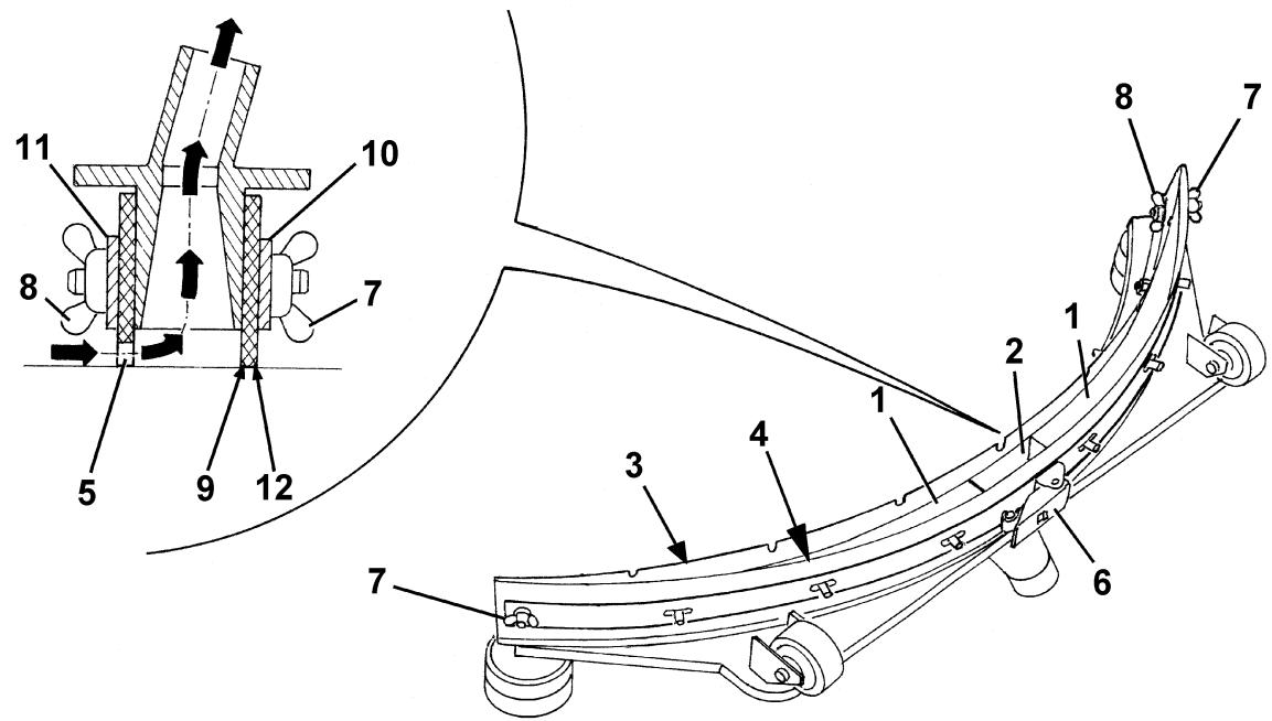
Squeezegee adjustment
- If necessary, stop the machine and adjust the balancing handwheel (16, Fig. C) of the squeegee (12).

CAUTION!
To avoid any damage to the floor surface, stop the brush/pad-holder rotation when the machine stops in one place, especially when the extra pressure function is on.
Working with brush/pad-holder extra pressure function turned on

NOTE
When the cylindrical brush deck is installed, the extra pressure function is disabled.
- If the floor proves to be particularly difficult to clean, it is possible to turn on the brush/pad-holder extra pressure function by pressing the switch (5, Fig. B).
- To return to normal pressure, press the switch (5, Fig. B) again.
The switch (5, Fig. B) is enabled only when the deck (4, Fig. C) is lowered and the switch warning light (4, Fig. B) is on.

CAUTION!
In case of brush/pad-holder motor overload, due to foreign material which prevent the brushes/pad-holders from rotating, or to excessively aggressive floors/brushes, the safety system stops the brushes/pad-holders after about one minute of continuous overload. The overload condition is shown by the three warning lights (7a, 7b, 7c, Fig. B) flashing simultaneously.
If the overload takes place when the extra pressure function is on, the system automatically reduces the pressure on the brushes/pad-holders, thus turning the extra pressure function off. If the overload persists, the brushes/pad-holders stop.
To start scrubbing again after a brush/pad-holder stop due to overload, stop the machine by turning the ignition key (12,
Fig. B) to "0". Restart the machine by turning the ignition key to "I".
Battery discharge during operation
-
Until the green warning light (7a, Fig. B) stays on, the batteries allow the machine to work normally. When the green warning light (7a) turns off and first the yellow warning light (7b) and then the red warning light (7c) turn on, it is necessary to charge the batteries.
-
When the yellow warning light (7b) turns on, the machine residual autonomy will last for a few minutes (depending on battery type).
- When the red warning light (7c) turns on the machine autonomy is over: after a few seconds the brushes/pad-holders are automatically stopped and the deck is automatically lifted. Only the machine vacuum and drive systems still operate, just to dry the wet floor and move the machine to the charging area.

CAUTION!
Do not use the machine with discharged batteries, to avoid damaging the batteries and reducing the battery life.

NOTE
In case the machine drive system cannot be used to move the machine, see
Pushing/towing the machine paragraph.
TANK EMPTYING
An automatic float shut-off system (5, Fig. I) stops the vacuum system when the recovery water tank (15) is full.
The vacuum system deactivation is signalled by a sudden increase in the vacuum system motor noise frequency.
When the recovery water tank (15, Fig. I) is full, empty it according to the following procedure.
Recovery water tank emptying
- Stop the machine by releasing the pedal (3, Fig. C).
- Lift the brush/pad-holder deck and the squeezegee by pressing the switch (4, Fig. B).
- Drive the machine to the appointed disposal area.
- Empty the recovery water tank through the hose (10, Fig. C). After working, rinse the tank with clean water.
Solution or washing water tank emptying
- Carry out steps 1 to 3.
- Empty the solution or washing water tank using the tap (24, Fig. C). After working, rinse the tank with clean water.
AFTER USING THE MACHINE
After working, before leaving the machine:
- Remove the brushes/pad-holders according to the procedure shown in the relevant paragraph.
- Empty the tanks (15 and 16, Fig. I) according to the procedure shown in the previous paragraph.
- Perform the daily maintenance procedures (see the Maintenance chapter).
- Store the machine in a clean and dry place, with the brushes/pad-holders and the squeegee lifted or removed.
To push/tow the machine easily when the drive system cannot be used, unlock the electromagnetic brake (27, Fig. C) according to the following procedure:
- Screw down completely the internal screws (29, Fig. C) (by turning them clockwise) with the supplied key.
When pushing/towing procedure is over, unscrew the screws (29, Fig. C) for 3 turns approximately, to lock the electromagnetic brake (27).

WARNING!
If the screws (29, Fig. C) are not unscrewed as shown, the electromagnetic brake is deactivated.

WARNING!
Do not start the machine when the electromagnetic brake unlocking screws (29, Fig. C) are screwed (electromagnetic brake deactivated).
MACHINE LONG INACTIVITY
If the machine is not going to be used for more than 30 days, proceed as follows:
- Perform the procedures shown in After using the machine paragraph.
-
Disconnect the battery red connector (4, Fig. J) by proceeding as follows:
-
Lift the covers (1 and 13, Fig. I) and check that the tanks (15 and 16) are empty, otherwise drain them through the drain hose (10, Fig. C) and the tap (24).
- Close the covers (1 and 13, Fig. I).
-
Carefully lift the tank assembly (1, Fig. J).
-
Drain the EDS-ECO Dosage Solution, according to the procedure shown in Maintenance chapter (only for machine equipped with EDS-ECO Dosage Solution (optional)).
FIRST PERIOD OF USE
After the first 8 hours, check the machine fastening and connecting parts for proper tightening. Check the visible parts for integrity and leakage.
MAINTENANCE
The lifespan of the machine and its maximum operating safety are ensured by correct and regular maintenance.
The following chart provides the scheduled maintenance. The intervals shown may vary according to particular working conditions, which are to be defined by the person in charge of the maintenance.

WARNING!
The procedures must be carried out with the machine off and the battery disconnected.
Moreover, before performing the maintenance, carefully read all the instructions in Safety chapter.
All scheduled or extraordinary maintenance procedures must be performed by qualified personnel, or by an authorised Service Center.
This Manual contains the Scheduled Maintenance Table and describes only the easiest and most common maintenance procedures.

NOTE
For other maintenance procedures shown in the Scheduled Maintenance Table, refer to the Service Manual that can be consulted at any Service Center.
SCHEDULED MAINTENANCE TABLE
| Procedure | Daily or after using the machine | Weekly | Every six months | Yearly |
| Squeezegee cleaning | ||||
| Brush/cylindrical brush cleaning | ||||
| Tank and vacuum grid with float cleaning | ||||
| Battery charging | ||||
| Squeezegee blade check and replacement | ||||
| Side skirt check | ||||
| Solution filter cleaning | ||||
| Battery (WET) fluid level check | ||||
| Screw and nut tightening check | (1) | |||
| Check and adjustment of driving belts from motors to cylindrical brushes | (2) | |||
| Squeezegee cable sliding shoe lubrication | (2) | |||
| Electromagnetic brake efficiency check | (2) | |||
| Brush/pad-holder motor carbon brush check or replacement | (2) | |||
| Vacuum system motor carbon brush check or replacement | (2) | |||
| Drive system motor carbon brush check or replacement | (2) |
(1): After the first 8 working hours
(2): This maintenance procedure must be performed by an authorized Nilfisk-Advance Service Center
MACHINE WORKING HOUR CHECK
- Insert the ignition key (12, Fig. B) and turn it to "I".
- In the first 5 seconds of machine operation, the display (8, Fig. B) shows the total number of working hours (scrubbing/drying) performed by the machine. Turn the ignition key (12, Fig. B) to "0".
SQUEEGEE CLEANING

NOTE
The squeezegee must be clean and its blades must be in good conditions in order to get a good drying.

CAUTION!
It is advisable to wear protective gloves when cleaning the squeegee because there may be sharp debris.
- Drive the machine on a level floor.
- Insert the ignition key (12, Fig. B) and turn it to "I".
- Lower the squeegee (12, Fig. C) by pressing the switch (6, Fig. B).
- Turn the ignition key (12, Fig. B) to "0".
- Disconnect the vacuum hose (11, Fig. C) from the squeegee.
- Loosen the handwheels (15, Fig. C) and remove the squeegee (12).
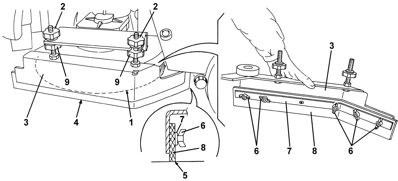
- Wash and clean the squeegee. In particular, clean the compartments (1, Fig. F) and the hole (2) from dirt and debris. Check the front blade (3) and the rear blade (4) for integrity, cuts and tears; otherwise replace them.
- Assemble in the reverse order of disassembly.
SQUEEGEE BLADE CHECK AND REPLACEMENT
-
Clean the squeegee as shown in the relevant paragraph.
-
Check that the edges (5 and 12, Fig. F) of the front (17, Fig. C) and rear blades (18) lay down on the same level, along all their length; otherwise adjust their height according to the following procedure:
-
Disengage the fastener (6, Fig. F) and loosen the wing nuts (7) to adjust the rear blade (4); then tighten the wing nuts and engage the fastener.
-
Loosen the wing nuts (8, Fig. F) to adjust the front blade (3); then tighten the wing nuts.
-
Check the front blade (3, Fig. F) and the rear blade (4) for integrity, cuts and tears; otherwise replace them according to the following procedure. Check that the front corner (9) of the rear blade is not worn; otherwise, overturn the blade to replace the worn corner with an integral one. If the other corners are worn too, replace the blade according to the following procedure.
-
To replace (or overturn) the rear blade (4) disengage the fastener (6), unscrew the wing nuts (7) and remove the retaining strip (10). Install the blade in the reverse order of removal.
- To replace the front blade (3) unscrew the wing nuts (8) and remove the retaining strip (11). Install the blade in the reverse order of removal.
After replacing (or overturning) the blades, adjust the blade height as shown in the previous step.
- Install the squeegee (12, Fig. C) and screw down the handwheels (15).
- Connect the vacuum hose (11, Fig. C) to the squeezegee (12).
- If necessary, adjust the squeegee balance adjusting handwheel (16, Fig. C).
BRUSH/CYLINDRICAL BRUSH CLEANING

CAUTION!
It is advisable to wear protective gloves when cleaning the brushes because there may be sharp debris.
- Remove the brushes from the machine, as shown in Use chapter.
- Clean and wash the brushes with water and detergent.
- Check the brush bristles for integrity and wear; if necessary, replace the brushes.
TANK AND VACUUM GRID WITH FLOAT CLEANING
- Drive the machine to the appointed disposal area.
- Turn the ignition key (12, Fig. B) to "0".
- Lift the covers (1 and 13, Fig. I).
- Clean and wash with clean water the covers (1 and 13, Fig. I), the tanks (15 and 16) and the grid (5) of the vacuum automatic shut-off. Drain the water in the tanks through the hose (10, Fig. C) and the tap (24).
- If necessary, release the fasteners (1, Fig. G) and open the grid (2); recover the float (3), clean all the components and then reinstall them.
- Check the tank cover gasket (4, Fig. G) for integrity.

NOTE
The gasket (4, Fig. G) creates vacuum in the tank, which is necessary for vacuuming the recovery water.
If necessary replace the gasket (4, Fig. G) by removing it from its housing (5). When assembling the new gasket, install the joint (6) in the rear central area, as shown in the figure.
- Check the seating surface (7, Fig. G) of the gasket (4) for integrity and sealing capabilities.
- Close the covers (1 and 13, Fig. I).
DETERGENT TANK CLEANING (Optional)
If equipped, clean the detergent tank (9, Fig. 1) (optional) according to the following procedure:
- Lift the tank assembly (1, Fig. J).
Unscrew the union (7, Fig. J) and remove the hose from the tank (8).
To remove the tank (8, Fig. J) release the fastener. - Wash and clean the detergent tank (8, Fig. J) in the appointed detergent disposal area.
Install the tank (8, Fig. J) and connect the union (7). - Carefully close the tank assembly (1, Fig. J).
EDS-ECO DOSAGE SOLUTION DRAINING (Optional)
- Clean the detergent tank, then remove the detergent remained in the hoses and in the pump.
- Drive the machine to the appointed detergent disposal area.
- Turn the ignition key (12, Fig. B) to "I".
- Turn on the EDS-ECO Dosage Solution by pressing the switch (9, Fig. B). Check that the green warning light turns on.
- Simultaneously press the switches (9 and 10a, Fig. B), until the warning light of the switch (9) start flashing (after about 5 seconds).
- Release the switches and wait for the switch warning light (9, Fig. B) to stop flashing.
- Turn the ignition key (12, Fig. B) to "0".
- Open the cover (13, Fig. I) and check that the hose (12) is empty, otherwise repeat steps 3 to 8.

NOTE
The draining cycle lasts about 10 seconds, then the vacuum function automatically turns on, which allows to remove the detergent remained.

NOTE
The draining cycle can also be performed with the detergent tank (9, Fig. 1) full of water, thus cleaning the system thoroughly. It is advisable to perform the draining cycle when the EDS-ECO Dosage Solution is really dirty/encrusted because the machine has not been used/cleaned for a long time.

NOTE
The draining cycle can be performed also to quickly fill the detergent supply hose (12, Fig. I) when the tank (9) is full but the hose (12) is still empty.

NOTE
If necessary, the draining cycle can be repeatedly performed.
SIDE SKIRT CHECK AND REPLACEMENT
Check
-
Drive the machine on a level floor.
-
Turn the ignition key (12, Fig. B) to "0".
-
On both sides of the machine, unscrew the knobs (2, Fig. D) and remove the side skirt assemblies (3).
-
Wash and clean the side skirts.
-
Check that the side skirt lower edge (4, Fig. D):
-
lays down on the same level, along all its length
is integral and free from cuts and lacerations
has the inner corner (5, Fig. D) that is not worn.
Otherwise overturn or replace the skirts according to the following procedure.
Overturning or replacement
- Unscrew the wing nuts (6, Fig. D) and remove the retaining strip (7).
- Remove the skirt blade (8, Fig. D) and, if possible, overturn the blade to replace the lower inner corner (5) with an integral one. If the other three corners are all worn, replace the blade.
Assembly and height adjustment
- Install the blades (8, Fig. D) and the skirt assemblies (3) in the reverse order of disassembly.
- Start the machine and lower the deck (4, Fig. C), then check that the side skirt blades (8, Fig. D):
slightly touch the floor
- during machine operation, the side blades (8, Fig. D) collect the solution, otherwise stop the machine and adjust the skirt height using the knobs (2) and (9). After adjusting, tighten the knobs.
SOLUTION FILTER CLEANING
- Drive the machine on a level floor.
- Turn the ignition key (12, Fig. B) to "0".
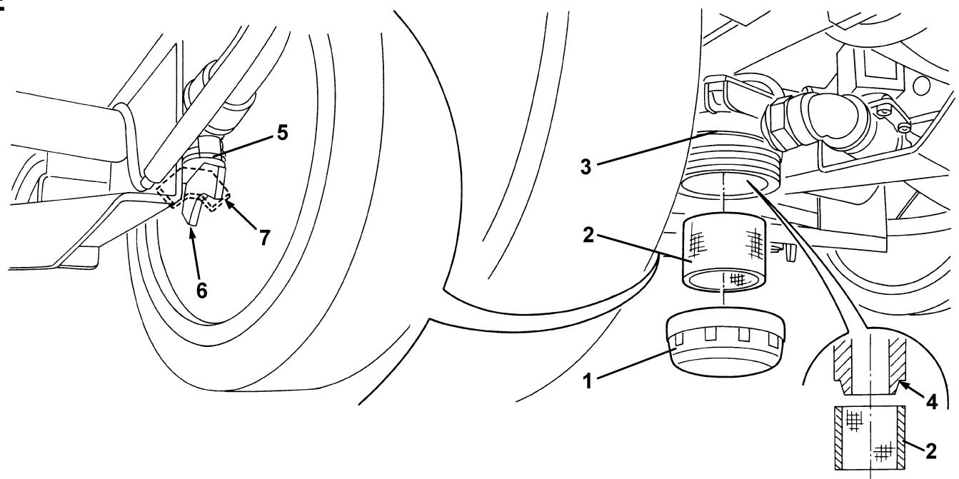
- Operating under the machine, behind the rear right wheel, close the solution or washing water tap (5, Fig. E). The tap (5, Fig. E) is closed when it is on the position (6) as to the hoses; it is open when it is on the position (7).
- Remove the transparent cover (1, Fig. E) and the strainer (2) under the machine, in front of the rear right wheel. Clean and assemble the components on the support (3).

NOTE
Properly install the strainer (2, Fig. E) in the housing (4) of the support (3).
- Reopen the tap (5, Fig. E).
BATTERY CHARGING

NOTE
Charge the batteries when the yellow and the red warning lights (7b or 7c, Fig. B) turn on, or when finishing cleaning.

CAUTION!
Keeping the batteries charged make their life last longer.

CAUTION!
When the batteries are discharged, charge them as soon as possible, as that condition makes their life shorter.
Check for battery charge at least once a week.

CAUTION!
The battery charger must be appropriate for the batteries installed on the machine.

WARNING!
Battery charging produces highly explosive hydrogen gas. Charge the batteries in well-ventilated areas and away from naked flames.
Do not smoke while charging the batteries. While charging the battery, always keep the tank assembly open.

WARNING!
Pay careful attention when charging the batteries as there may be battery fluid leakages. The battery fluid is corrosive. If it comes in contact with the skin or eyes, rinse thoroughly with water and consult a physician.
Charging the batteries with an external battery charger
- Drive the machine on a level floor.
- Lift the covers (1 and 13, Fig. I) and check that the tanks (15 and 16) are empty, otherwise drain them through the drain hose (10, Fig. C) and the tap (24).
- Close the covers (1 and 13, Fig. I).
- Carefully lift the tank assembly (1, Fig. J).
-
For WET batteries only:
-
Check the level of electrolyte inside the batteries (2, Fig. J). If necessary, adjust the level through the caps (5, Fig. J).
-
Leave the caps (5, Fig. J) open for the next battery charge.
If necessary, clean the upper surface of the batteries. -
Check that the external battery charger is suitable by referring to the Battery Charger Manual. The battery charger voltage rating shall be 24V .
- Disconnect the battery connector (4, Fig. J) and connect it to the external battery charger.
- Connect the battery charger to the electrical mains.
- When the recharging is complete, disconnect the battery charger from the electrical mains and from the battery connector (4, Fig. J).
- (For WET batteries only) Check the level of electrolyte inside the batteries and close all the caps (5, Fig. J).
- Connect the battery connector (4, Fig. J) to the machine.
- Carefully close the tank assembly (1, Fig. J).
- Fill the tanks (15 and 16, Fig. I); now the machine is ready to be used.
Battery charging with (optional) battery charger installed on the machine
- Drive the machine on a level floor.
-
For WET batteries only:
-
Lift the covers (1 and 13, Fig. I) and check that the tanks (15 and 16) are empty, otherwise drain them through the drain hose (10, Fig. C) and the tap (24).
- Close the covers (1 and 13, Fig. I).
- Carefully lift the tank assembly (1, Fig. J).
- Check the level of electrolyte inside the batteries (2, Fig. J). If necessary, adjust the level through the caps (5, Fig. J).
-
When the correct level is reached, close the caps (5, Fig. J) and clean, if necessary, the upper surface of the batteries.
-
Connect the battery charger cable plug (8, Fig. C) to the electrical mains (voltage and frequency must be compatible with the battery charger values on the machine serial number plate).

NOTE
When the battery charger is connected to the electrical mains, all machine functions are automatically cut off.
If the red warning light (7, Fig. H) on the battery charger control panel stays on, the battery charger is charging the batteries.
- When the green warning light (9, Fig. H) turns on, the battery charging is completed.
- Once the battery charging is completed, disconnect the battery charger cable plug (8, Fig. C) from the electrical mains, then roll up the cable and insert it into its housing (7).
-
For WET batteries only:
-
Carefully close the tank assembly (1, Fig. J).
- Fill the tanks (15 and 16, Fig. I).
- Now the machine is ready to be used.

NOTE
For further information about the battery charger (10, Fig. H) operation, see the relevant Manual.
FUSE CHECK/REPLACEMENT
- Turn the ignition key (12, Fig. B) to "0".
- Unscrew the nuts (5, Fig. H) and carefully remove the cover (1).
- Check/replace the drive system electronic board protection fuse (60A): (3, Fig. H)
- Install the cover and screw the nuts.
BRUSH/PAD-HOLDER DECK OR CYLINDRICAL BRUSH DECK DISASSEMBLY/ASSEMBLY

NOTE
According to the following instructions, it is possible to install on the machine either the brush/pad-holder deck (1, Fig. K) or the cylindrical brush deck (16).
To assemble/disassemble the deck it is not necessary to remove the brushes/pad-holders.
Disassembly
- Drive the machine on a level floor.
- Lower the deck (4 or 5, Fig. C) by pressing the switch (4, Fig. B).
- Turn the ignition key (12, Fig. B) to "0".
- (For brush/pad-holder deck) Disconnect the electrical connector (3, Fig. K).
(For cylindrical brush deck) Disconnect the electrical connectors (3 and 11, Fig. K), then install the protection cover (12) on the connector.
- Disconnect the solution supply hose (4, Fig. K).
- Remove the two cotter pins (6, Fig. K).
- Unscrew the knob (5, Fig. K) and remove the brush/pad-holder deck (1) or the cylindrical brush deck (13).
Assembly
- Assemble in the reverse order of disassembly.
SAFETY FUNCTIONS
The machine is equipped with the following safety functions.
EMERGENCY STOP BUTTON
It is located in a position (2, Fig. B) that is easily accessible for the operator. Press it in case of immediate necessity to stop all machine functions.
To reset it, turn it clockwise.
SPEED REDUCTION
It reduces the machine speed in case of turns exceeding a specified angle.
DRIVER'S SEAT MICROSWITCH
It is inside the driver's seat and it prevents machine movement and brush rotation when the operator is not on the seat.
ELECTROMAGNETIC BRAKE
Built-in the front wheel, it keeps the machine stopped when the machine is off, when the emergency stop button is pushed and when the forward gear pedal is not pressed.
TROUBLESHOOTING
| TROUBLE | POSSIBLE CAUSE | REMEDY |
| The motors do not work; no warning light turns on | Disconnected battery connector (4, Fig. J) | Connect |
| Completely discharged batteries | Charge | |
| The machine does not move | The machine has been turned on with the ignition key (12, Fig. B) while pressing the pedal (3, Fig. C) | Turn the machine off and then turn it on without pressing the gear pedal |
| At the machine start-up, the warning light (4, Fig. B) of the switch flashes and the brushes do not work | The machine has been turned off without lifting the brush deck | Wait for the deck to lift before turning on again the brushes by pressing the switch (4, Fig. B) |
| The warning lights (7, Fig. B) flash simultaneously | Brush motor overload | Use less aggressive brushes suitable for the floor to be cleaned or avoid working with extra pressure function turned on |
| The brushes do not work, the red warning light (7c, Fig. B) is on | Discharged batteries | Charge |
| Insufficient dirty water vacuuming | Full recovery water tank (15, Fig. I) | Empty |
| Clogged vacuum grid (5, Fig. I) or stuck closed float | Clean | |
| Hose (11, Fig. C) disconnected from the squeezegee | Connect | |
| Dirty squeezegee (12, Fig. C), or worn or damaged squeezegee blades | Clean the squeezegee or overturn/replace the blades | |
| Incorrectly closed tank cover, or damaged gasket (2, Fig. I) | Correctly close the cover or clean/replace the gasket | |
| Insufficient solution or washing water flow to the brushes | Empty solution or washing water tank | Fill |
| Dirty solution filter (2, Fig. E) | Clean | |
| Dirty tank (16, Fig. I), clogged output hole | Clean | |
| Insufficient detergent flow to the brushes (for machine equipped with EDS-ECO Dosage Solution) | Detergent flow percentage too low | Increase it, according to the procedure shown in the relevant chapter |
| Detergent supply hose empty | Drain the EDS-ECO Dosage Solution, with the detergent tank (9, Fig. I) full, until the supply hose (12, Fig. I) is full. | |
| Clogged EDS-ECO Dosage Solution | Drain the EDS-ECO Dosage Solution, with the detergent tank (9, Fig. I) full of water, to thoroughly clean the system. | |
| Marks caused by the squeezegee | Debris under the squeezegee blades | Clean |
| Worn, chipped or torn squeezegee blades | Overturn or replace | |
| The squeezegee has not been balanced with the handwheel (16, Fig. C) | Balance |

NOTE
If the machine has an optional battery charger installed, the machine cannot operate if the charger is not on board. In case of battery charger malfunction, contact an authorised Service Center.
For further information, apply to Nilfisk-Advance Service Centers.
SCRAPPING
Have the machine scrapped by a qualified scrapper.
Before scrapping the machine, remove and separate the following materials, which must be disposed of properly according to the Law in force:
Batteries
Brushes
- Plastic hoses and components
- Electrical and electronic components (*)
(*): Refer to the nearest Nilfisk-Advance Center especially when scrapping electrical and electronic components.
INLEIDING 2
DOEL EN INHOUD VAN DEZE HANDLEIDING 2
BETREFFENDE PERSONEN 2
OPBERGEN VAN DE HANDLEIDING 2
BEWIJS VAN CONFORMITEIT 2
IDENTIFICATIEGEGEVENS 2
ANDERE GEBRUIKERSHANDLEIDINGEN 2
VERVANGINGSONDERDELEN EN ONDERHOUD 2
MODIFICATIONS EN VERBETERINGEN 2
VEILIGHEID 2
GEBRUIKTE SYMBOLEN 3
ALGEMENE INSTRUCTIES 3
VERPAKKING VERWIJDEREN/AFLEVERING 4
BESCHRIJVING VAN DE MACHINE 5
BEDRIJFSCAPACITEIT 5
ALGEMENE OPMERKINGEN 5
BESCHRIJVING 5
ACCESSIONS / OPTIES 8
GEBRUIK 9
CONTROLE / VOORBEREIDINGEN VOOR EEN ACCU OP EEN NIEUWE MACHINE 9
MONTAGE VAN DE ACCU EN INSTELLEN VAN HET TYPE ACCU (WET OF GEL) 10
VOOR HET STARTEN 10
DE MACHINE STARTEN EN STOPPEN 12
MACHINE IN BEDRIJF 12
LEGEN VAN DE RESERVOIRS 13
NA GEBRUIK VAN DE MACHINE 14
DUW-/TREKBEWEGING VAN DE MACHINE 14
LANGE PERIODE VAN STILLSTAND 14
EERSTE GEBRUIKSPERIODE 14
ONDERHOUD 14
ONDERHOUDSSCHEMA 15
CONTROLE VAN DE BEDRIJFSUREN VAN DE MACHINE 15
REINIGING TREKKER 15
CONTROLE EN VERVANGING VAN DE RUBBERS VAN DE TREKKER 16
REINIGING VAN DE SCHIJFBORSTELS/CILINDRISCHE BORSTELS 16
REINIGING VAN DE RESERVOIRS EN VAN HET AANZUIGROOSTER MET VLOTTER 16
REINIGING VAN HET RESERVOIR MET REINIGINGSMIDDEL (optioneel) 16
EDS SPOELEN (TOEVOERSYSTEEM REINIGINGSMIDDEL) (optioneel) 17
CONTROLE EN VERVANGING VAN DE ZIJFLAPS 17
REINIGING VAN HET FILTER VAN HET REINIGINGSMIDDEL 18
ACCU'S OPLADEN 18
CONTROLE / VERVANGING VAN DE ZEKERINGEN 19
DEMONTAGE/MONTAGE VAN HET SCHROBDEK VAN DE SCHIJFBORSTELHOUDER/PADHOUDER
OF HET SCHROBDEK MET DE HOUDER VOOR DE CILINDRISCHE BORSTELS 19
VEILIGHEIDSFUNCTIES 19
KNOP VOOR NOODSTOP 19
VERMINDERING VAN DE SNELHEID IN BOCHTEN 19
MICROSCHAKELAAR VAN DE BESTUURDERSTSOEL 19
ELEKTROMAGNETISCHE REM 19
STORINGEN LOKALISEREN 20
VERWIJDERING 20
INLEIDING
DOEL EN INHOUD VAN DEZE HANDLEIDING
ACCESSORIES / OPTIES
- GEVAAR
LETOP
WAARSCHUWING - ADVIES


- EINLEITUNG 2
- UTILISATION 9
- ENTRETIEN 14
- FONCTIONS DE SECURITE 19
- DEPISTAGE DES PANNES 20
- MISE EN DECHARGE 20
- INTRODUCTION
- BUT ET CONTENU DU MANUEL
- CONSERVATION DU MANUEL
- SAFETY 2
- UNPACKING/DELIVERY 4
- MACHINE DESCRIPTION 5
- USE 9
- MAINTENANCE 14
- SAFETY FUNCTIONS 19
- TROUBLESHOOTING 20
- SCRAPPING 20
- MANUAL PURPOSE AND CONTENTS
- TARGET
- HOW TO KEEP THIS MANUAL
- CONFORMITY CERTIFICATE
- NOTE
- IDENTIFICATION DATA
- OTHER REFERENCE MANUALS
- SPARE PARTS AND MAINTENANCE
- CHANGES AND IMPROVEMENTS
- SAFETY
- SYMBOLS
- DANGER!
- WARNING!
- CAUTION!
- CONSULTATION
- GENERAL INSTRUCTIONS
- UNPACKING/DELIVERY
- MACHINE DESCRIPTION
- CONVENTIONS
- DESCRIPTION
- Control panel
- (See Fig. B)
- Outside view
- (See Fig. C)
- View under tank covers (See Fig. 1)
- View under tank assembly (See Fig. J)
- Brush/pad-holder deck and cylindrical brush deck view (See Fig. K)
- WIRING DIAGRAM
- (See Fig. L)
- Colour codes
- ELECTRICAL FUSES
- Fuses
- ACCESSORIES/OPTIONS
- USE
- BATTERY CHECK/SETTING ON A NEW MACHINE
- BATTERY INSTALLATION AND BATTERY TYPE SETTING (WET OR GEL)
- Machine setting
- Battery charger setting (if equipped)
- Battery installation
- Battery charging
- BEFORE START-UP
- Deck installation/removal
- Brush/pad-holder installation/removal
- Cylindrical brush installation/removal
- Squeegee installation
- Solution or washing water tank filling
- Detergent tank filling (optional)
- Operator's position adjustment
- MACHINE START AND STOP
- Start
- Stopping the machine
- MACHINE OPERATION
- Detergent flow percentage adjustment
- Squeezegee adjustment
- Working with brush/pad-holder extra pressure function turned on
- Battery discharge during operation
- TANK EMPTYING
- Recovery water tank emptying
- Solution or washing water tank emptying
- AFTER USING THE MACHINE
- MACHINE LONG INACTIVITY
- FIRST PERIOD OF USE
- MAINTENANCE
- MACHINE WORKING HOUR CHECK
- SQUEEGEE CLEANING
- SQUEEGEE BLADE CHECK AND REPLACEMENT
- BRUSH/CYLINDRICAL BRUSH CLEANING
- TANK AND VACUUM GRID WITH FLOAT CLEANING
- DETERGENT TANK CLEANING (Optional)
- EDS-ECO DOSAGE SOLUTION DRAINING (Optional)
- SIDE SKIRT CHECK AND REPLACEMENT
- Check
- Overturning or replacement
- Assembly and height adjustment
- SOLUTION FILTER CLEANING
- Charging the batteries with an external battery charger
- Battery charging with (optional) battery charger installed on the machine
- FUSE CHECK/REPLACEMENT
- BRUSH/PAD-HOLDER DECK OR CYLINDRICAL BRUSH DECK DISASSEMBLY/ASSEMBLY
- Disassembly
- Assembly
- SAFETY FUNCTIONS
- EMERGENCY STOP BUTTON
- SPEED REDUCTION
- DRIVER'S SEAT MICROSWITCH
- ELECTROMAGNETIC BRAKE
- SCRAPPING
- INLEIDING 2
- VEILIGHEID 2
- VERPAKKING VERWIJDEREN/AFLEVERING 4
- BESCHRIJVING VAN DE MACHINE 5
- GEBRUIK 9
- ONDERHOUD 14
- VEILIGHEIDSFUNCTIES 19
- STORINGEN LOKALISEREN 20
- VERWIJDERING 20
- INLEIDING
- DOEL EN INHOUD VAN DEZE HANDLEIDING
- ACCESSORIES / OPTIES
Brand : NILFISK
Model : BR 651
Category : Scrubber