
X-17 - Mixer TASCAM - Free user manual and instructions
Find the device manual for free X-17 TASCAM in PDF.
| Product type | 4-channel DJ mixer |
| Brand | TASCAM |
| Model | X-17 |
| Dimensions (W x H x D) | 482 x 176 x 102 mm |
| Weight (unit only) | 4.3 kg |
| Weight (power adapter) | 0.8 kg |
| Power supply | PS-P17X power adapter, 120 V/230 V (50/60 Hz), 27 W |
| Power consumption | 27 W |
| Line inputs (PGM 1-4) | 4 x RCA unbalanced, level -10 dBV, impedance 10 kΩ |
| Phono/line inputs (PGM 1-4) | 4 x RCA unbalanced, selectable phono (MM) or line, impedance 47 kΩ in phono |
| Microphone inputs | 1 x Combo XLR/TRS (front) + 1 x XLR (rear) for main mic, 1 x TRS (rear) for auxiliary mic |
| Master outputs | 1 x XLR balanced (+4 dBu) + 1 x RCA unbalanced (0 dBV) |
| Booth outputs | 1 x RCA unbalanced (0 dBV) |
| Rec outputs | 1 x RCA unbalanced (-10 dBV) |
| Aux outputs | 1 x RCA unbalanced (0 dBV) |
| Effects loop (send/return) | 6.35 mm TRS jack unbalanced, level -4 dBV |
| Headphone output | 6.35 mm stereo jack, 2 x 100 mW into 33 Ω |
| PGM channel equalizer | 3-band (HI, MID, LO): +12 dB to -26 dB |
| Mic equalizer | 2-band (HI, LO): +12 dB to -12 dB |
| Crossfader | Horizontal, adjustable curve, user-replaceable |
| Sampler | 3 samples, 16-bit, up to 30 seconds each, save to CompactFlash card |
| Fader start function | Yes, via mini-jacks for crossfader side A and B |
| Maintenance and cleaning | Clean with a dry cloth; do not use liquid or abrasive products |
| Safety | Read manual carefully, do not expose to water or heat, unplug during storms, use only provided adapter |
| Spare parts and repairability | For any repair, contact a TASCAM dealer. The crossfader can be replaced by the user (see manual). |
| General information | Class A product: may cause radio interference in domestic environments. Operating temperature: 5°C to 35°C, humidity 30% to 90% non-condensing. |
Frequently Asked Questions - X-17 TASCAM
User questions about X-17 TASCAM
0 question about this device. Answer the ones you know or ask your own.
Ask a new question about this device
Download the instructions for your Mixer in PDF format for free! Find your manual X-17 - TASCAM and take your electronic device back in hand. On this page are published all the documents necessary for the use of your device. X-17 by TASCAM.
USER MANUAL X-17 TASCAM
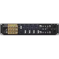
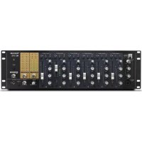
Professional DJ Mixer
OWNER'S MANUAL/ MODE D'EMPLOI / BEDIENUNGSANLEITUNG / MANUALE D'ISTRUZIONI / Mezclador de DJ profesional


CAUTION
RISK OF ELECTRIC SHOCK DO NOT OPEN

CAUTION: TO REDUCE THE RISK OF ELECTRIC SHOCK, DO NOT REMOVE COVER (OR BACK). NO USER-SERVICEABLE PARTS INSIDE. REFER SERVICING TO QUALIFIED SERVICE PERSONNEL.

The lightning flash with arrowhead symbol, within an equilateral triangle, is intended to alert the user to the presence of uninsulated "dangerous voltage" within the product's enclosure that may be of sufficient magnitude to constitute a risk of electric shock to persons.

The exclamation point within an equilateral triangle is intended to alert the user to the presence of important operating and maintenance (servicing) instructions in the literature accompanying the appliance.
This appliance has a serial number located on the bottom. Please record the model number and serial number and retain them for your records.
Model number
Serial number
WARNING: TO PREVENT FIRE OR SHOCK HAZARD, DO NOT EXPOSE THIS APPLIANCE TO RAIN OR MOISTURE.
IMPORTANT (for U.K. Customers)
DO NOT cut off the mains plug from this equipment. If the plug fitted is not suitable for the power points in your home or the cable is too short to reach a power point, then obtain an appropriate safety approved extension lead or consult your dealer.
If nonetheless the mains plug is cut off, remove the fuse and dispose of the plug immediately, to avoid a possible shock hazard by inadvertent connection to the mains supply.
If this product is not provided with a mains plug, or one has to be fitted, then follow the instructions given below:
IMPORTANT. DO NOT make any connection to the larger terminal which is marked with the letter E or by the safety earth symbol 12 or coloured GREEN or GREEN-and-YELLOW.
The wires in the mains lead on this product are coloured in accordance with the following code:
BLUE
BROWN
:NEUTRAL
: LIVE
As these colours may not correspond with the coloured markings identifying the terminals in your plug proceed as follows:
The wire which is coloured BLUE must be connected to the terminal which is marked with the letter N or coloured BLACK.
The wire which is coloured BROWN must be connected to the terminal which is marked with the letter L or coloured RED.
When replacing the fuse only a correctly rated approved type should be used and be sure to re-fit the fuse cover.
IF IN DOUBT — CONSULT A COMPETENT ELECTRICIAN.
For U.S.A
TO THE USER
This equipment has been tested and found to comply with the limits for a Class A digital device, pursuant to Part 15 of the FCC Rules. These limits are designed to provide reasonable protection against harmful interference when the equipment is operated in a commercial environment. This equipment generates, uses, and can radiate radio frequency energy and, if not installed and used in accordance with the instruction manual, may cause harmful interference to radio communications.
Operation of this equipment in a residential area is likely to cause harmful interference in which case the user will be required to correct the interference at his own expense.
CAUTION
Changes or modifications to this equipment not expressly approved by TEAC CORPORATION for compliance could void the user's authority to operate this equipment.
For the consumers in Europe
WARNING
This is a Class A product. In a domestic environment, this product may cause radio interference in which case the user may be required to take adequate measures.
1) Read these instructions.
2) Keep these instructions.
3) Heed all warnings.
4) Follow all instructions.
5) Do not use this apparatus near water.
6) Clean only with dry cloth.
7) Do not block any ventilation openings. Install in accordance with the manufacturer's instructions.
8) Do not install near any heat sources such as radiators, heat registers, stoves, or other apparatus (including amplifiers) that produce heat.
9) Do not defeat the safety purpose of the polarized or grounding-type plug. A polarized plug has two blades with one wider than the other. A grounding type plug has two blades and a third grounding prong. The wide blade or the third prong are provided for your safety. If the provided plug does not fit into your outlet, consult an electrician for replacement of the obsolete outlet.
10) Protect the power cord from being walked on or pinched particularly at plugs, convenience receptacles, and the point where they exit from the apparatus.
11)Only use attachments/accessories specified by the manufacturer.
12) Use only with the cart, stand, tripod, bracket, or table specified by the manufacturer, or sold with the apparatus. When a cart is used, use caution when moving the cart/apparatus combination to avoid injury from tip-over.

13) Unplug this apparatus during lightning storms or when unused for long periods of time.
14) Refer all servicing to qualified service personnel. Servicing is required when the apparatus has been damaged in any way, such as power-supply cord or plug is damaged, liquid has been spilled or objects have fallen into the apparatus, the apparatus has been exposed to rain or moisture, does not operate normally, or has been dropped.
- Do not expose this apparatus to drips or splashes.
- Do not place any objects filled with liquids, such as vases, on the apparatus.
- Do not install this apparatus in a confined space such as a book case or similar unit.
- The apparatus draws nominal non-operating power from the AC outlet with its POWER switch in the off position.
Table of contents
Introduction 4
Some notes and precautions 4
Serial number, etc. 4
Rack-mounting the unit 4
Features and controls 5
Top panel. 6
How to replace the fader 8
Rear panel. 8
Sampler 9
Specifications. 11
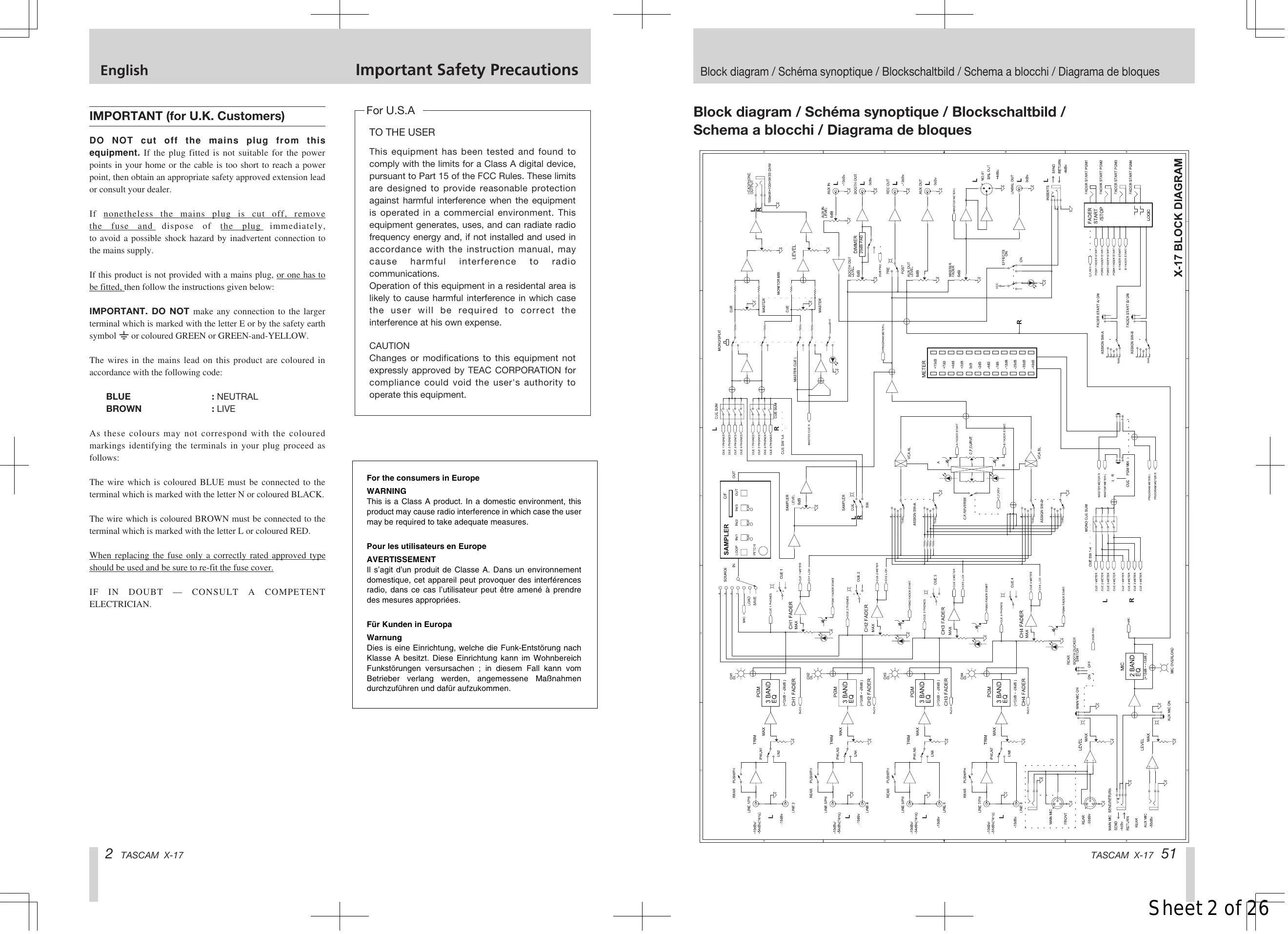
Block diagram. 51
Introduction
The X-17 is a sophisticated 4-PGM DJ mixer which allows you to connect many devices, and mix in a creative way. With a sophisticated layout, the X-17 combines easy operation with a wide range of functions.
It is VERY IMPORTANT that you read this manual before connecting and using the mixer, in order to get the best out of it.
We recommend contacting our authorized Technical Service department, or that of your TASCAM dealer or distributor if any maintenance or repair work is necessary, so that you can continue to enjoy the best possible performance and operation.
Some notes and precautions
Treat the X-17 as you would any other piece of precision equipment.
Avoid exposing it to extremes of temperature and humidity and avoid mechanical shocks and vibration.
Keep the unit away from strong magnetic fields (TV sets, computer monitors, large electric motors, etc.).
Environmental considerations
The X-17 may be used in most areas, but to maintain top performance, and prolong operating life, observe the following environmental conditions:
The nominal temperature should be between 5^ and 35^ (41^ and 95^)
Relative humidity should be 30 to 90 degrees noncondensing.
As the unit may become hot during operation, always leave sufficient space above and around the unit for ventilation.
Do not install this equipment in a confined space such as a bookcase or similar unit. You should not place the unit on a piece of equipment generating heat, an amplifier for example, to avoid possible problems with overheating.
Only use the AC adaptor provided with the X-17, and do not use the adaptor with any other equipment. Always make sure that the voltage supplied to the adaptor matches the input voltage as specified on the adaptor. In case of doubt, consult a qualified electrician.
To avoid hum in the audio, make sure that the power cable is far away from the signal cables.
NOTE
When transporting the unit, always use the original packing materials or a properly-designed equipment case. For this reason, we strongly recommend that you save all the packing materials that came with the X-17, in case you need to transport it in the future.
Connections to other equipment
It is extremely important that the power is turned off on all units when making or breaking connections to or from the X-17.
When turning power on, it is usually a good idea to start with the source (turntables, CD players, etc.), then the X-17 and finish with the amplifier system.
Turning power off should be done in the other direction (amplifiers first, then other equipment).
If you have to turn off the X-17 and turn it on again, always wait for 3 or more seconds between turning the unit off and on again.
Serial number, etc.
The serial number of the X-17 is located on a sticker at the rear of the unit on the bottom panel. Make a note of this for future reference (warranty, etc.).

Rack-mounting the unit


Features and controls

Top Panel
① MAIN MIC input
Connect the main microphone to this XLR/TRS connector that can accept both balanced and unbalanced signals.
This is a "combotype jack which accepts both XLR type and 1 / 4 TRS type connectors.
Connections are as follows:
XLR TRS
GND: Pin 1 Sleeve
HOT: Pin 2 Tip
COLD: Pin 3 Ring
NOTE
There is another MAIN MIC input connector on the rear panel. Only use either the connector on the rear panel or the top panel (you cannot use both at the same time).
The MAIN MIC channel also has a dedicated insert jack on the rear panel.
② ON switch and indicator for MAIN MIC channel
Push for on, and push again for off. When this switch is on, the MAIN MIC channel is active and the indicator lights.
(3) MAIN MIC LEVEL
Adjusts the signal level of both the top and rear MAIN MIC inputs.
④ OL indicator
When the MAIN MIC and/or AUX MIC input signal cause an overload, this indicator lights (post-insert, but pre-EQ).
NOTE
All input adjustments must be done very carefully. Use the level meters and/or headphones for reference. Make sure that the top red meter LEDs do not all light up, as this shows that the signal can clip (overload and distort).
⑤ MIC EQ
2-band EQ (HI and LO, both cutting and boosting by 12 dB) affecting both the the MAIN MIC and AUX MIC input signals.
⑥ ON switch and indicator for AUX MIC channel
Push for on, and push again for off. When this switch is on, the AUX MIC (auxiliary microphone) channel is active and the indicator lights.
⑦ AUX MIC LEVEL
Adjusts the signal level of the AUX MIC input.
⑧ TRIM controls and OL indicators
Adjust the input signal level for each PGM.
If a PGM's input signal causes an overload, the PGM's OL indicator lights.
NOTE
All input sensitivity adjustments must be done very carefully. Use the level meter and/or headphones for reference. Make sure that the top red meter LEDs do not all light up, as this shows that the signal can clip (overload and distort).
⑨ PGM EQ
Provides three-band EQ (equalization) for each PGM signal. The control for each band can cut the band by up to 26 dB and boost it by up to 12 dB.
If all EQ controls on a PGM are set to -26dB , this will almost completely cut the signal of the PGM.
10 Input Selector switches
Select the input signal for each PGM. Each PGM can select from either a LINE input or a PHONO/LINE input (the selection between phono and line is made on the rear panel).
CUE switches and indicators
Sends the pre-fader signals of the PGMs to the CUE monitor bus. When CUE is activated for a PGM, the CUE indicator lights.
12 PGM faders
Adjust the level of the PGMs
13 FADER START switches
Set the automatic start of A and B using the cross-fader on or off.
14 Cross-fader ASSIGN selectors
Select the signal sources assigned to the A and B cross-fader outputs. Each of the four PGMs can be selected as a signal source, and there is also a THRU setting, which means that no PGM is assigned to the cross-fader on that side. Use the PGM and MASTER faders to adjust the output if this setting is made.
15 Cross-fader
Mixes between the A and B outs, assigned from the PGM signals.
The cross-fader can be reversed, and you can set the cross-fader curve to match your preferences (see below).
It is possible for you to replace the cross-fader if this becomes necessary (see below for details).
C.F CURVE
Allows you to adjust the cross-fader response curve from soft (counter-clockwise) to hard (clockwise).
C.F REVERSE
Sets the direction of the cross-fader.
When in the OFF, position, moving the cross-fader toward A increases the volume of the A signal and moving the cross-fader toward B increases the volume of the B signal. The ON setting reverses this
18Meters
This pair of peak meters indicates either the post-fader (PGM or MASTER) MASTER signal level in stereo, or the mono CUE signal levels.
19 Meter selection switch (L/R -CUE/PROG)
Switches the meter indication between the MASTER program (the switch is up) and the CUE signals (the switch is depressed).
20 EFFECTS ON switch and indicator
When this switch is on, the indicator lights, and the master external effect loop is active.
② MASTER fader
Adjusts the level of the signal from the MASTER OUTPUT jacks (both the balanced XLR and the unbalanced RCA connectors).
22 AUX IN LEVEL
Adjusts the level of the signals from the AUX IN jacks.
23 AUX IN
Use these unbalanced RCA connectors to connect line level equipment, such as CD players, cassette decks, DAT decks, MD players, or another X-17, etc. This input signal is input immediately pre-MASTER fader.
24 AUX OUT LEVEL
Adjusts the signal level output from the AUX OUTPUT jacks.
25 BOOTH OUT LEVEL
Adjusts the signal level output from the BOOTH OUTPUT jacks.
26 REC OUTPUT
These unbalanced RCA jacks output the pre-MASTER fader signal. This can be useful for a number of purposes: for example, you could connect a recorder to these jacks, and record your live performance without the MASTER level affecting the recording.
PRE/POST insert switch for REC OUT
This switch controls what is output from the REC OUT jacks. When this switch is in the PRE setting (the switch is depressed):
The four PGM signals and the sampler signal, without the master insert loop.
In the POST setting:
The four PGM signals and the sampler signal, with the master insert loop, the AUX IN signal, and both the MAIN and AUX MIC signals.
28 CompactFlash™ card slot
This slot holds a CompactFlash card which you can use to save sampled sounds from the X-17's internal memory, and to load them into the X-17's internal memory. This allows you to carry your favorite samples in a compact, robust format.
The card can only be inserted in one direction. Press the eject button to the right of the slot to eject the card.
Cover this slot using the attached protective cover when it is not in use.
See the section on the sampler below for full details of how to use the card and the sampler.
CompactFlash is a trademark of the CompactFlash Association.
29 S AMPLER SOURCE selector
SAVE: Saves the X-17's internal sample data to the CompactFlash card.
LOAD: Loads sample data from the CompactFlash card into the X-17's internal memory.
MIC, 1-4: Select the sampling source (the MIC inputs or any of the 4 PGMs).
30 SAMPLER PITCH
Adjusts the sampler's playback pitch and speed from half speed (SLOW) to double speed (FAST).
③ SAMPLER LEVEL
Adjusts the output level of the sampler signal.
32 S AMPLER CUE switch and indicator
Sends the sampler pre-LEVEL signal to the CUE monitor (the indicator lights when this is activate).
33 S AMPLER LOOP key and indicator
Toggles sampler loop play on and off (the indicator lights when sampler loop play is active).
34 IN/<- keys (IN1, IN2, IN3)
Start sample recording or playback. When the SAMPLER SOURCE selector is set to LOAD, these keys load sample data from the CompactFlash card.
OUT key
Stops sample recording or playback. When the SAMPLER SOURCE selector is set to SAVE, this key saves the X-17's internal sample data to the CompactFlash card.
36 MONO SPLIT switch and indicator
Selects headphone monitoring mode: either MONOSPLIT mode (the indicator is lit) or STEREO mode (the indicator is unlit).
STEREO mode: You monitor the CUE signal and MASTER signal as determined by the PAN control.
MONO SPLIT: You monitor the CUE signals in mono from the left headphone, and the MASTER signal in mono from the right headphone.
③ Monitor MIX
Adjusts the balance in the headphones between the CUE signal and the MASTER signal.
38 PHONES LEVEL
Adjusts level of the signals output through the headphones.
39 PHONES
Connect a standard pair of stereo headphones to this 1/4 jack.
How to replace the cross-fader
- Move the fader to the top and remove the fader knob.
- Remove the two screws retaining the fader.
- Remove the fader.
- Unplug the multiway connector connecting the X-17 to the fader.
- Replace the fader with a new one, and connect the multiway connector to the new fader.
- Secure the new fader with the screws removed in the first step.
Rear Panel
40 AC Adaptor in
Use this jack to connect the PS-P17X AC adapter which comes with your X-17.
Insert the plug following the arrow position of the AC adapter plug, and the white dot on the rear panel.
WARNING
DO NOT use any adapter with the X-17 except the PS-P17X adapter supplied with the X-17.
Connect the AC adapter jack to the X-17 in the way shown on the illustration on the rear panel of the X-17. If you connect the AC adapter in any other way, you may damage the X-17.
41 POWER switch
42 BOOTH DIMMER switch
When this switch is on, and when the MAIN MIC ON switch is pressed, the level of the signal from the BOOTH OUTPUT jacks is reduced by 20dB.
43 BOOTH OUTPUT
These unbalanced RCA connectors output the pre-MASTER fader signal, whose level is adjusted using the BOOTH OUT control.
Use the BOOTH DIMMER switch to reduce the level of this signal.
44 AUX OUTPUT
These unbalanced RCA connectors output the pre-MASTER fader signal, whose level is adjusted using the AUX OUT control.
45 MASTER OUTPUT (UNBAL)
These unbalanced RCA connectors output the master output signals (post-MASTER fader).
46 SEND/RETURN
Use these 1 / 4 TRS connectors (unbalanced) to insert an external effect in the MASTER OUTPUT signal path. This includes the four PGMs and the sampler.
The connector is wired as follows.
GND: Sleeve
SEND: Tip
RETURN: Ring
47 MASTER OUTPUT (BAL)
These balanced XLR connectors output the master output signals (post-MASTER fader), wired as follows:
GND: Pin 1
HOT: Pin 2
COLD: Pin 3
48 FADER START connectors
Connect devices supporting the fader start operation to these mini-jacks.
You can enable the cross-fader start function independently for the A and B outputs.
Move the cross-fader to start and/or stop (back cue) the PGM A or B source automatically.
NOTE
The fader start signal is output from the tip, and the fader stop (back cue) signal is output from the sleeve. The ground for these connections is provided by the signal ground of the device to which the fader start is made.
49 LINE inputs
Use these unbalanced RCA jacks to connect line level equipment, such as CD players, cassette decks, MD decks, etc.
50 PHONO/LINE inputs
When the appropriate PUSH PHONO switch is in the PHONO position (pushed in), connect turntables equipped with MM (moving magnet) cartridges to these
unbalanced RCA jacks. When the switch is in the LINE position (out) connect line level equipment, such as CD players, cassette decks, MD decks, etc.
Always use the supplied shorting RCA plugs in any PHONO jacks where a turntable is not connected.
WARNING
When the PUSH PHONO switch is set to PHONO, only connect turntables equipped with an MM cartridge to these connectors. Do not connect such turntables to any other connectors.
⑤ SIGNAL GND terminals
If the turntables you use are fitted with grounding wires, connect them to these GND terminals to reduce noise and hum.
52 PUSH PHONO switches
Push this switch in to use the odd-numbered (1, 3, 5 and 7) LINE/PHONO inputs with turntables. Leave it out to use these inputs with other equipment (CD players, MD decks, etc.).
WARNING
Turn the power OFF on all amplifier systems, etc. when using these switches. When these switches are pressed, loud noises are produced that may damage hearing and equipment.
53 MAIN MIC SEND/RETURN
Use this TRS 1/4 jack (unbalanced) to inserts an external effect in the MAIN MIC signal path.
The connections are follows:
GND: Sleeve
SEND: Tip
RETURN: Ring
54 AUX MIC input
Connect an auxiliary microphone to this balanced TRS connector, wired as follows:
GND: Sleeve
HOT: Tip
COLD: Ring
55 MAIN MIC input
Connect the microphone to this balanced XLR connector, wired as follows:
GND: Pin 1
HOT: Pin 2
COLD: Pin 3
NOTE
There is another MAIN MIC input connector on the top panel. Only use either the connector on the rear panel or the top panel (you cannot use both at the same time).
Sampler
The X-17 includes three samplers, each of which can record 30 seconds of sample data at 16-bit resolution. These samples can be stored on and loaded from a CF card (card formats other than CompactFlash do not work with the X-17) of at least 16MB capacity.
NOTE
The X-17 uses TASCAM's own sample data format. You can only use an X-17 to load and save sample data.
Sampling
You can record samples from PGMs 1 through 4 or from the MIC signals. When making a sample, the sampling point is at the pre-fader point of PGMs 1 through 4.
-
Use the SAMPLER SOURCE selector to select the sampling source (PGM 1-4 or MIC).
-
To start sampling, press an unlit IN key (IN1, IN2 or IN3). The unlit key shows that the sampler is empty. Sampling starts, the IN key lights, and the OUT key starts to flash.
-
Stop recording by pressing the OUT key. If the maximum recording time (30 seconds) is reached, recording will stop automatically. The IN key you pressed earlier, and the OUT key both light.
Erasing sample data
When a sampler contains data (its IN key is lit), press and hold the OUT key and press the IN key to erase the sample data. The IN key goes out. If no samplers contain data, the OUT key goes out as well.
Playback
- When a sampler contains data (its IN key is lit) press its IN key to start playback. The appropriate PLAY indicator lights and playback starts from the beginning of the sample. Pressing any IN key again during playback will start playback from the start of the appropriate sample (including the currently-playing one).
NOTE
Note that the X-17 can hold three samples but only one can be played at a time.
- Use the LEVEL knob to adjust the output level.
- Stop playback by pressing the OUT. The appropriate PLAY indicator goes out.
LoopedPlayback
- Press LOOP key to light it. When it is lit, pressing one of the IN keys starts looped playback, and the appropriate PLAY indicator lights.
- When the LOOP key is lit, and looped playback is going on, you can press LOOP to turn off the key and stop the looping. This does not stop the playback, though. Playback stops at the end of the sample (or when you press the OUT key).
Sampler pitch and tempo control
- Use the PITCH control to adjust the playback pitch and speed. The pitch range is from half speed (SLOW) to double speed (FAST).
Saving samples to a CompactFlash card
Note that when you turn off the X-17, all sample data not saved on cards is lost. Save samples to a CompactFlash card using the procedure described here.
- Insert the Compact Flash card into the slot.
NOTE
Note that this operation erases all data on the card. If there is any data you want to keep on a card, you should not save to that card.
- Set the SAMPLER SOURCE selector to the SAVE position. The OUT key starts to flash.
- Press the OUT key. It lights and the save operation starts. If any data is already stored on the card, it is deleted, and the save starts. As data is saved from each sample, the IN key for that sample flashes.
- After the last sample has been saved, the OUT key flashes, and the IN keys return to the state they were in before the save operation (lit keys indicate a sample is present).
Loading samples from a CompactFlash card
NOTE
Note that this operation erases all samples currently in the X-17's memory. If there are any samples in memory that you want to keep, you should save them to another card first.
- Insert the CompactFlash card into the slot.
- Set the SAMPLER SOURCE SELECTOR to the LOAD position. The IN1/<- key starts to flash.
- Press the IN1/<- key. It flashes, and the load operation starts.
- After the load operation has finished and samples have been loaded, the IN keys light (if one sample has been loaded, IN1 lights, if two samples have been loaded, IN1 and IN2 light, if three samples have been loaded, all keys light. If there were no samples to be loaded on the card, no keys are lit.
- After the load operation is finished, the IN keys corresponding to the loaded samples will light. If no samples have been loaded from the card, no keys will be lit.
Specifications
LINE IN (PGM1-4):
RCA, unbalanced
Input level: -10 dBV
Input impedance: 10 kΩ
PHONO/LINE inputs (PGM1-4)
RCA, unbalanced
PHONO position
Input level: -54 dBV
Input impedance: 47 kΩ
RIAA equalization
LINE position
Input level: -10 dBV
Input impedance: 10 kΩ
MAIN MIC input (on the top panel)
XLR/TRS, balanced/unbalanced
Input level: -50 dBV
Input impedance: 2.8 kΩ
MAIN MIC input (on the rear panel)
XLR, balanced
Input level: -50 dBV
Input impedance: 2.8 kΩ
AUX MIC input (on the rear panel)
TRS, balanced/unbalanced
Input level: -50 dBV
Input impedance: 2.8 kΩ
AUX IN (on the top panel)
RCA, unbalanced
Input level: -10 dBV
Input impedance: 10 kΩ
MASTER OUTPUTS (BAL)
XLR, balanced
Nominal output level: +4 dBu
Output impedance: 75 Ω
MASTER OUTPUTS (UNBAL)
RCA, unbalanced
Nominal output level: 0 dBV
Output impedance: 100 Ω
BOOTH OUTPUT: RCA, unbalanced Nominal output level: 0 dBV Output impedance: 100Ω
REC OUTPUT: RCA, unbalanced Nominal output level: -10 dBV Output impedance: 100Ω
AUX OUTPUT: RCA, unbalanced Nominal output level: 0 dBV Output impedance: 100Ω
SEND/RETURN
TRS, unbalanced
Nominal output levelsend): -4 dBV
Output impedance: 100 Ω
Input level.return): -4 dBV
Input impedance: 10 kΩ
MAIN MIC SEND/RETURN
TRS, unbalanced
Nominal output level send): -4 dBV
Output impedance: 100 Ω
Input level (return): -4 dBV
Input impedance: 10 kΩ
PHONES: 100mW + 100mW (at 33
Audio Performance
| Frequency response: | |
| LINE IN: | 20 Hz to 20 kHz, +/-1.0 dB |
| PHONO IN: | 30 Hz to 15 kHz, +/-2.0 dB (RIAA) |
| MIC IN: | 30 Hz to 18 kHz, +/-3.0 dB |
| Signal to nose ratio: | |
| LINE IN: | 78 dB (IHF A Weighting) |
| PHONO IN: | 70 dB (IHF A Weighting) |
| MIC IN: | 60 dB (IHF A Weighting) |
| Total harmonic distortion: | |
| LINE IN: | <0.1 % |
| PHONO IN: | <0.2 % |
| MIC IN: | <0.2 % |
| Crosstalk | >60 dB (@1 kHz) |
| PGM EQ | |
| HI: | +12 dB to -26 dB |
| MID: | +12 dB to -26 dB |
| LO: | +12 dB to -26 dB |
| Filter (cut frequency at -6dB, slope 12dB/oct) | |
| HI: | 6.5 kHz |
| MID: | 6.5 kHz & 200 Hz |
| LO: | 200 Hz |
| MIC EQ | |
| HI: | 5.5 kHz, +12 dB to -12 dB |
| LO: | 125 Hz, +12 dB to -12 dB |
| Power requirement: | 120 V (60 Hz) |
| 230 V (50Hz) | |
| Power consumption: | 27 W |
| Dimension (w x h x d): | 482 x 176 x 102 (mm) |
| 19 x 6.9 x 4 (in) | |
| Weight: | 4.3 kg, 9.48 lbs (main unit) |
| 0.8 kg, 1.8 lbs (PS-P17X AC adaptor) | |
| Applicable electromagnetic environment: | |
| E4 | |
| Peak inrush current: | 1.6 A |
| Supplied accessories | |
| Shorting RCA plug for PHONO x 8 | |
| AC Adaptor (PS-P17X) x 1 | |
| Operation manual x 1 | |
All specifications subject to change without notice.


34 Touches IN/<- (IN1, IN2, IN3)
HOT: pointe (point chaud)
34 IN/<- Tasten (IN1, IN2, IN3)
Lineeingang (PGM1-4)
Cinch, unsymmetrisch
34 Tasti IN/<- (IN1, IN2, IN3)
PHONO IN: 70 dB (pesato IHF A)
MIC IN: 60 dB (pesato IHF A)
MID: 6.5 kHz & 200 Hz
LO: 200Hz
MIC EQ
HI: 5.5kHz, + 12dB / - 12dB
LO: 125Hz, + 12dB / - 12dB
Tensione di alimentazione: 120V (60Hz) 230V (50Hz)
MASTER OUTPUTS (BAL)
XLR, balanceado
Nivel Salah nominal: +4dBu
Impedancia de salute: 75 ohmios
MASTER OUTPUTS (UNBAL)
RCA, no balanceado
Nivel Salah nominal: 0 dBV
PHONO IN: 70 dB (IHF MEDICION A)
MIC IN: 60 dB (IHFMEDICION A)
TEAC Professional Division
X-17
TEAC CORPORATION
| Phone: (0422) 52-5082 | 3-7-3, Nakacho, Musashino-shi, Tokyo 180-8550, Japan |
| TEAC AMERICA, INC. | |
| Phone: (323) 726-0303 | 7733 Telegraph Road, Montebello, California 90640 |
| TEAC CANADA LTD. | |
| Phone: 905-890-8008 Facsimile: 905-890-9888 | 5939 Wallace Street, Mississauga, Ontario L4Z 1Z8, Canada |
| TEAC MEXICO, S.A. de C.V. | |
| Phone: (525) 581-5500 Facsimile: (525) 581-5111 | Campesinos 184. Col. Granjas Esmeralda. 09810.Mexico D.F. |
| TEAC UK LIMITED | |
| Phone: 01923-819699 | 5 Marlin House, Croxley Business Park, Watford, Hertfordshire, WD18 8TE U.K. |
| TEAC DEUTSCHLAND GmbH | |
| Phone: 0611-71580 | Bahnstrasse 12, 65205 Wiesbaden-Erbenheim, Germany |
| TEAC FRANCE S. A. | |
| Phone: 01.42.37.01.02 | 17 Rue Alexis-de-Tocqueville, CE 005 92182 Antony Cedex, France |
| TEAC BELGIUM NV/SA | |
| Phone: 0162-510860 | Oeverkruid 15, NL-4941 VV Raamsdonksveer, Netherlands |
| TEAC NEDERLAND BV | |
| Phone: 0162-510210 | Oeverkruid 15, NL-4941 VV Raamsdonksveer, Netherlands |
| TEAC AUSTRALIA PTY.,LTD. A.C.N. 005 408 462 | |
| Phone: (03) 9644-2442 | 106 Bay Street, Port Melbourne, Victoria 3207, Australia |
| TEAC ITALIANA S.p.A. | |
| Phone: 02-66010500 | Via C. Cantù 11, 20092 Cinisello Balsamo, Milano, Italy |


- CAUTION
- IMPORTANT (for U.K. Customers)
- For U.S.A
- TO THE USER
- For the consumers in Europe
- WARNING
- Table of contents
- Introduction
- Some notes and precautions
- Environmental considerations
- NOTE
- Connections to other equipment
- Serial number, etc.
- Rack-mounting the unit
- Top Panel
- ① MAIN MIC input
- ② ON switch and indicator for MAIN MIC channel
- MAIN MIC LEVEL
- ④ OL indicator
- ⑤ MIC EQ
- ⑥ ON switch and indicator for AUX MIC channel
- ⑦ AUX MIC LEVEL
- ⑧ TRIM controls and OL indicators
- ⑨ PGM EQ
- Input Selector switches
- CUE switches and indicators
- PGM faders
- FADER START switches
- Cross-fader ASSIGN selectors
- Cross-fader
- C.F CURVE
- C.F REVERSE
- 18Meters
- Meter selection switch (L/R -CUE/PROG)
- EFFECTS ON switch and indicator
- ② MASTER fader
- AUX IN LEVEL
- AUX IN
- AUX OUT LEVEL
- BOOTH OUT LEVEL
- REC OUTPUT
- PRE/POST insert switch for REC OUT
- CompactFlash™ card slot
- S AMPLER SOURCE selector
- SAMPLER PITCH
- ③ SAMPLER LEVEL
- S AMPLER CUE switch and indicator
- S AMPLER LOOP key and indicator
- IN/<- keys (IN1, IN2, IN3)
- How to replace the cross-fader
- Rear Panel
- FADER START connectors
- LINE inputs
- PHONO/LINE inputs
- ⑤ SIGNAL GND terminals
- PUSH PHONO switches
- MAIN MIC SEND/RETURN
- AUX MIC input
- MAIN MIC input
- Sampler
- Sampling
- Erasing sample data
- Playback
- LoopedPlayback
- Sampler pitch and tempo control
- Saving samples to a CompactFlash card
- Loading samples from a CompactFlash card
- Specifications
- Audio Performance
- Touches IN/<- (IN1, IN2, IN3)
- IN/<- Tasten (IN1, IN2, IN3)
- Tasti IN/<- (IN1, IN2, IN3)
- TEAC Professional Division
- X-17
- TEAC CORPORATION
Brand : TASCAM
Model : X-17
Category : Mixer