ReadyWarm 8900 Outdoor Microclimate - Gas Heating CECOTEC - Free user manual and instructions
Find the device manual for free ReadyWarm 8900 Outdoor Microclimate CECOTEC in PDF.


| Product Type | Outdoor Gas Patio Heater |
| Brand | Cecotec |
| Model | ReadyWarm 8900 Outdoor Microclimate |
| Category | Gas Heating |
| Dimensions (H x D) | 220 cm x 80 cm |
| Weight | 18 kg |
| Power Source | Propane/Butane Gas Bottle (not included) |
| Heat Output | 10 kW |
| Gas Consumption | 800 g/h |
| Heating Area | Up to 20 m² |
| Main Material | Stainless Steel and Tempered Glass |
| Color | Black and Silver |
| Ignition Type | Piezoelectric |
| Safety Protection | Tip-over protection, low oxygen safety, thermocouple |
| Power Adjustment | Variable (from 1 to 10 kW) |
| Main Functions | Outdoor heating, microclimate |
| Maintenance and Cleaning | Regularly clean the burner and grill; check for obstructions |
| Spare Parts and Repairability | Burner, thermocouple, gas hose, piezoelectric igniter available |
| Included Accessories | Protective cover, user manual |
| Warranty | 2 years |
| Standards | CE, EN 14543 |
Frequently Asked Questions - ReadyWarm 8900 Outdoor Microclimate CECOTEC
User questions about ReadyWarm 8900 Outdoor Microclimate CECOTEC
0 question about this device. Answer the ones you know or ask your own.
Ask a new question about this device
Download the instructions for your Gas Heating in PDF format for free! Find your manual ReadyWarm 8900 Outdoor Microclimate - CECOTEC and take your electronic device back in hand. On this page are published all the documents necessary for the use of your device. ReadyWarm 8900 Outdoor Microclimate by CECOTEC.
USER MANUAL ReadyWarm 8900 Outdoor Microclimate CECOTEC
natural_image
Exterior view of a modern outdoor patio with a tall metal frame and ventilation grilles (no text or symbols visible)ES • Este producto no es adecuado para calefacción primaria. Este producto está indicado para ser utilizado únicamente en lugares abrigados o para una utilización puntual. | EN • This product is not suitable for primary heating purposes. This product is only suitable for well insulated spaces or occasional use. | FR • Ce produit ne convient pas pour une utilisation en tant que chauffage primaire. Cet appareil a été conçu seulement pour être utilisé dans des espaces intérieurs ou pour une utilisation momentanée. | DE • Dieses Produkt ist nicht für als Hauptheizgerät geeignet. Dieses Produkt ist nur für geschutzten Orten oder zur gelegentlichen Verwendung geeignet. | IT • Questo prodotto non è adatto a riscaldamento primario. Questo prodotto è indicato solamente per luoghi caldi o per uso sporadico. | PT • Este produto não é adequado para ser usado como aquecimento primário. Destina-se a uma utilização ocasional e apenas em locais abrigados. | NL • Dit product is niet geschikt voor primaire verwarming. Dit product is alleen geschikt voor gebruik op beschutte plaatsen of voor incidenteel gebruik. | PL • Ten produkt nie nadaje się do pierwotnego ogrzewania. Ten produkt jest wskazany tylko do miejsc ostonietych lub do okazjonalnego użytku. | CZ • Tento produkt není vhodný pro primární vytápění. Tento výrobek je určen pouze na topení na chráněných místech nebo pro příležitostné použití.
Manual de instrucciones Instruction manual Manuel d'instructions Bedienungsanleitung Manuale di istruzioni Manual de instruções Handleiding Instrukcja obstugi Návod k použití
Safety instructions 10
-
Parts and components 68
-
Before use 68
-
Assembly 68
-
Operation 72
-
Cleaning and maintenance 73
-
Troubleshooting 73
-
Technical specifications 74
-
Disposal of old electrical appliances 75
-
Technical support and warranty 76
SOMMAIRE
Please read the following safety instructions before using the heater.
- If you smell gas, turn off the gas switch, extinguish any open flames. If the smell persists, call the fire service immediately.
- Do not use the product to store petrol or other flammable vapours or liquids or store such substances near the product.
- A gas cylinder which is not connected for use shall not be stored near this or any other appliance.
- The appliance is designed to be used outdoors or in well-ventilated areas. A well-ventilated area should have a minimum of 25 % of the surface area open.
- The surface area is the sum of the surface area of the walls.
- Improper installation, adjustment, alteration, service or maintenance can cause injury or property damage.
- Read the installation, operating and maintenance instructions carefully before installing or repairing the equipment.
- This appliance must be installed, and the gas cylinder stored in accordance with current regulations.
- Do not obstruct the ventilation openings of the gas cylinder housing.
- Do not move the product during operation.
- Shut off the gas cylinder valve or the regulator before moving the appliance.
- The hose or flexible hose must be changed within the prescribed intervals.
- Use only the type of gas and type of cylinder specified by the manufacturer.
- The gas cylinder used with your heater must meet several requirements. Only purchase gas cylinders with the following dimensions: 31.8 cm (diameter) x 58 cm (height)
with a maximum capacity of 15 kg.
- In case of strong wind, special care must be taken to prevent the device from tilting.
- Keep the appliance at least 1 m away from the cylinder.
- The injector of this device is not removable and can only be assembled by manufacture.
- It is forbidden to change the gas pressure of the appliance.
- Do not connect the gas cylinder directly to the appliance without a regulator.
- Only use the type of gas and type of cylinder specified in the instructions.
- The regulator has to comply with EN 16129:2013 and the national pressure regulation corresponding to the category of the appliance.
- Use 30mbar regulator for butane/propane under the category 13B/P(30).
- Use 30mbar regulator for butane under the category 13+(28-30/37). Use 37mbar regulator for propane under the category 13+(28-30/37).
- Do not use the heater indoors, as this may cause personal injury or property damage.
- This outdoor heater is not intended for installation in recreational vehicles and/or boats.
- Installation and maintenance must be carried out by a qualified technician. Improper installation, adjustment, alteration, service or maintenance can cause injury or property damage.
- Do not attempt to alter the unit in any manner.
- Never replace or substitute the regulator with anything other than the one suggested.
- Do not store or use gasoline or other flammable vapours or liquids near the appliance.
- The entire gas system, hose, regulator, pilot or burner must be inspected for leaks or damage before use and at least annually by a qualified service person.
- All leak tests must be carried out with a soap solution. Never use an open flame to check for leaks.
- Do not use the heater until all connections have been checked.
- Turn off the gas valve immediately if the smell of gas is detected. If the leak is at the hose/regulator connection, tighten the connection and perform another leak test. If bubbles continue to appear, the hose is defective and must be returned to the place of purchase of the hose. If the leak is at the cylinder regulator/valve connection: disconnect, reconnect and perform another leak check. If you continue to see bubbles after several attempts, the cylinder valve is defective and should be returned to the place of purchase of the cylinder. Fig. 1
- Do not transport the heater while it is in operation.
- Do not move it until it has cooled down.
- Keep the vent opening of the gas cylinder free and clear of dirt.
- Do not paint the flame screen, control panel or top cover reflector.
- The control housing, the burner and the air circulation ducts of the heater must be kept clean.
- Frequent cleaning may be necessary.
- The gas cylinder must be turned off when the heater is not in use.
- Check the heater immediately if any of the following situations occur:
- Heater does not reach temperature.
- The burner makes a popping noise during use (a slight
noise is normal when the burner is switched off).
- Smell of gas together with yellow flame tips.
- The gas regulator/hose assembly must be located out of the way where people can trip over it or in an area where the hose is not subject to accidental damage.
- Any parts that have been removed to carry out maintenance on the heater must be replaced before the heater is put into operation.
- Adults and children should keep away from high temperature surfaces to avoid burns.
- Children must be continuously supervised when in the heater area.
- Clothing or other flammable materials must not be hung on or near the heater.
- Replace the gas cylinder in a well-ventilated area, away from any source of ignition (candle, cigarettes, other flame-producing appliances, etc.).
- Do not obstruct the ventilation openings of the cylinder housing.
- Close the cylinder valve or regulator after use.
- In the event of a gas leak, the appliance cannot be used, if it is switched on, turn off the gas supply, inspect and have the appliance repaired before using it again.
- Check the hose at least once a month, every time the cylinder is changed, or when the cylinder is to be used again after a period of time. If it shows signs of cracking, splitting or other deterioration it shall be exchanged for new hose of the same length and of the equivalent quality.
- The use of this device in enclosed areas can be dangerous and is prohibited.
- Read these instructions thoroughly before using the appliance. The appliance must be installed in accordance
with the instructions and local regulations.
- To connect the hose and the regulator, and to connect the regulator and the hose, please refer to the figure shown above.
- This product contains small batteries. Ingestion of small batteries may cause choking hazard. Seek immediate medical attention if batteries are swallowed or inhaled. Keep the batteries out of the reach of children.
Heater stand and location
- The heater is designed for outdoor use only. Always ensure that there is adequate fresh air ventilation.
- Always maintain an adequate distance from combustible materials, i.e., at least 100 cm at the top and 100 cm at the sides. Fig. 2
- The heater must be placed on a firm and levelled surface.
- Never operate the heater in an explosive atmosphere, such as in areas where petrol or other flammable liquids or vapours are stored.
- To protect the heater from strong wind, anchor the base securely to the ground with screws. Fig. 2
Gas requirements
- Use propane or butane gas only.
- The pressure regulator and hose assembly used must conform to local standards.
- The installation must conform to local codes or, in the absence of local codes, to the standard for storage and handling of liquefied petroleum gases.
- A dented, rusted or damaged gas cylinder can be dangerous and should be checked by your supplier. Never use a gas cylinder with a damaged valve connection.
- The gas cylinder must allow the extraction of vapour.
- Never connect an unregulated gas cylinder to the heater.
Leakage test
- Gas connections on the heater are leak tested at the factory prior to shipment. A complete gas tightness check must be performed at the installation site. This is due to possible mishandling in shipment or excessive pressure being applied to the heater.
- Prepare a soap solution with one part liquid detergent and one part water. The soap solution can be applied with a spray bottle or a cloth. Soap bubbles will appear in case of leakage.
- The heater should be checked with a full cylinder. Make sure the safety control valve is in the OFF position.
- Turn the gas supply on.
- In the event of a leak, turn the gas supply off. Tighten any leaking fittings, then turn the gas supply on and check again.
- Never perform the leak test while smoking.
INSTRUCTIONS DE SÉCURITÉ
- Reflector
- Flame screen
- Glass tube
- Protective grid
- Upper support
- Front panel
- Side panel
- Lower support
- Lower plate
2. BEFORE USE
- Take the product out of the box.
- Remove all packing material and keep the original box.
- Make sure all parts and components are included and in good conditions. If any sign of visible damage is observed, contact immediately with our official Technical Support Service.
3. ASSEMBLY
Tools needed:
- Philips screwdriver with medium blade
- Spray bottle of soap solution for leakage test
Parts list
Fig. 5
| Part | Description | Amount |
| - | Reflector | 1 |
| B | Flame screen | 1 |
| C | Glass tube | 1 |
| D | Upper support | 4 |
| E | Protective grid | 4 |
| F | Black silicone ring | 1 |
| G | Side panel | 3 |
| H | Front panel | 1 |
| I | Gas hose | 1 |
| J | Control box | 1 |
| K | Lower support | 4 |
| L | Blocking belt | 1 |
| M | Wheel assembly | 1 |
| N | Lower plate | 1 |
Components:
Fig. 6
AA. Wing nut (x2)
BB. Small flat washer 6 (x6)
CC. Stud (x3)
DD. 3/16" screw (x42)
EE. M6 X 12 bolt (x4)
FF. M6 Flange nut (x4)
GG. M5 X 12 screw (x6)
HH. Fixing bracket (x4)
II. Wrench (x1)
JJ. Philips screwdriver (x1)
KK. Knob (x1)
LL. M4 X 6 screw (x1)
MM. Chain (x1)
NN. Long stem lighter (x1)
Assembly procedures
- Assemble the wheel assembly to the bottom plate. Fix the wheel assembly to the bottom plate using 4 bolts M6X12 and 4 flange nuts M6. Fig. 7
Hardware used:
EE. M6 X 12 bolt (x4)
FF. M6 Flange nut (x4)
II. Wrench (x1)
- Unscrew the switch button, load the small battery, tighten the switch button.
Insert the pins of the base in the holes of the lower support, press to secure the pins. Use 4 M5X12 screws to secure the bottom support and base.
ENGLISH
Insert the pins of the control box in the holes of the upper support, press to secure the pins.
Use 4 x 3/16" screws to secure the upper support and the control box. Fig. 8
Hardware used:
GG. M5 X 12 screw (x4)
DD. 3/16" screw (x42)
JJ. Philips screwdriver (x1)
Mount the blocking belt.
Attach the blocking belt to the 2 lower support pieces behind the front door, using 2 M5X12
screws. Fig. 9
Hardware used:
GG. M5 X 12 screw (x2)
JJ. Philips screwdriver (x1)
- Install the central support. Insert the 4-piece upper support into the lower support.
Secure with 8 x 3/16" screws. Fig. 10
Hardware used:
DD. 3/16" screw (x8)
JJ. Philips screwdriver (x1)
- Fix the flame screen to the upper support. Use 8 x 3/16" screws. Fig. 11
Hardware used:
DD. 3/16" screw (x8)
JJ. Philips screwdriver (x1)
- Mount the reflector on the flame screen. Screw the 3 bolts onto the flame screen, put 3 washers φ 6 on the top of the bolt, then put the reflector on the bolt, secure them with 3 washers 6 and 3 wing nuts. Fig. 12
Hardware used:
AA. Wing nut (x2)
BB. Washer φ 6 (x6)
CC. Stud (x3)
- Carefully install the glass tube by lifting it up and inserting it through the centre hole in
the top plate. Make sure that the black silicone ring is attached to the bottom edge of the glass tube, as shown in the figure. Slide the glass tube through the hole in the bottom plate cover and over the centre plate. Check and make sure that the glass tube is well positioned and completely covers the central hole of the centre plate. Fig. 13
For easy installation, place the black silicone ring on the centre plate and then install the glass tube.
Make sure that the rim of the glass tube is firmly seated in the black silicone ring.
Warning
The black silicone ring must be in place before operating the heater.
- Mount the protective grid. Hang the hooks of the protective grid in the holes of the supports. Secure the protective grille to the fixing brackets with 4 x 3/16" screws. Fig. 14
Hardware used:
DD. 3/16" screw (x4)
JJ. Philips screwdriver (x1)
HH. Fixing bracket (x4)
- Attach the three side panels to the heater with 18 3/16" screws. Fig. 15
Note
Do not cover the front part where the knob is located.
Hardware used:
DD. 3/16" screw (x8)
JJ. Philips screwdriver (x1)
- Install the knob with the M4X6 screw. Hang the chain in the hole of the control box and place the hook of the front panel in the holes of the bottom plate. Fig. 16
Hardware used:
KK. Knob (x1)
LL. M4 X 6 screw (x1)
MM. Chain (x1)
JJ. Philips screwdriver (x1)
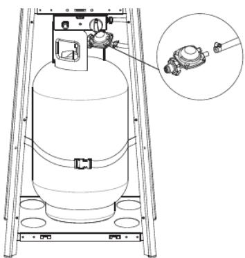
- Connect the gas hose and the regulator and then connect the regulator to the gas cylinder. Fig. 17
Warning
- Make sure that the hose does not come into contact with any high temperature surface, it may melt and cause a fire.
- After placing the cylinder inside the heater, secure it tightly with the locking belt.
- Leakage test
Fig. 18
Warning
A leak test must be carried out annually and every time a cylinder is connected or if a part of the gas system is replaced.
ENGLISH
Warning
Never use an open flame to check for leaks. Make sure there are no sparks or open flames in the area while checking for leaks. Sparks or open flames will cause fire or explosion, property damage, serious bodily injury or death.
Leakage test
- This should be done before first use, annually, and whenever any gas component is replaced or serviced. Do not smoke while performing this test and eliminate all sources of ignition.
- Refer to the leakage check diagram to detect the areas to be checked. Turn all the controls of the burners to the off position. Open the gas supply valve.
- Brush a half-and-half solution of liquid soap and water onto all joints and connections of the regulator, hose, manifolds and valves.
- Bubbles will indicate a gas leak. Tighten the loose gasket or replace the part with one recommended by Technical Support and have the heater inspected by a certified gas fitter.
- If the leak cannot be stopped, immediately turn off the gas supply, disconnect it and have the heater inspected by a certified gas fitter or dealer. Do not use the heater until the leak has been fixed.
4. OPERATION
To turn on the heater
- Turn on the valve on the gas supply cylinder completely.
- Press and turn the variable control knob to PILOT position (counter-clockwise 90°). Fig. 3
- Press and hold the variable control knob and hold for 90 seconds. While holding down the selector switch, press the power button several times until the pilot flame lights. Release the knob when the flame has ignited.
Note
- If a new cylinder has just been connected, it takes about a minute or more for the air in the gas hose to come out of the pilot hole. When it has come out, the pilot flame will light.
- When lighting the pilot flame make sure that the variable control knob is continuously pressed down while pressing the igniter button. Variable control knob can be released after the pilot flame lights.
- The pilot flame can be observed and checked from the small round window with sliding cover at the bottom of the flame screen (to the left or right side of the controller).
-
If the pilot flame does not light or goes out, repeat step 3. 4.
-
After the pilot flame lights, turn the variable control knob to maximum position and leave it there for 5 minutes or more before turning the knob to the desired temperature position.
Warning
Check that there is no broken glass before the operation.
Turning off the heater
- Turn the control knob to the "PILOT" position.
- Press and turn the variable control knob to the "OFF" position. Fig. 3
- Turn off the valve on the gas supply cylinder completely.
5. CLEANING AND MAINTENANCE
Cleaning and maintenance
- Wipe dust-covered surfaces with a soft, damp cloth. Do not clean the heater with combustible or corrosive cleaners.
- Remove dirt from the burner to keep it clean and safe for use.
- Cover the burner unit with the optional protective cover when the heater is not in use.
Storage
- Always close the gas valve on the cylinder after use or in the event of a fault.
- Remove the pressure regulator and hose.
- Check the gas valve for tightness and damage. If you suspect a fault, have it replaced by your gas supplier.
- Never store the gas cylinder underground, or in places without adequate air ventilation.
6. TROUBLESHOOTING
| Problem | Possible cause | Solution |
| Pilot flame does not light | Gas valve may be turned off | Open the gas valve |
| Empty gas cylinder | Replace or refill the cylinder | |
| Opening blocked | Clean or replace opening | |
| Air in supply system | Let the air out | |
| Loose or slack connections | Check the connections | |
| Pilot flame does not stay lit | Dirt around the pilot | Clean the area thoroughly |
| Loose or slack connections | Tighten connections | |
| Defective thermocouple | Replace thermocouple | |
| Gas leak in line | Check the connections | |
| Lack of fuel pressure | Gas cylinder almost emptyReplace or refill the cylinder | |
| The burner does not turn on | Pressure is low | Gas cylinder almost emptyReplace or refill the cylinder |
| Opening blocked | Clean the area thoroughly | |
| Not switched on | Turn valve to "ON" | |
| Defective thermocouple | Replace thermocouple | |
| Pilot light assembly bent | Place pilot properly | |
| Not in the correct location | Place it properly and retry |
If the appliance is defective or has a problem during installation or use, do not attempt to repair it yourself, but contact your supplier or dealer to solve the problem.
7. TECHNICAL SPECIFICATIONS
Construction and characteristics
- Transportable terrace/garden heater with cylinder housing
- Casing in steel with powder-coating or stainless steel
- Gas hose connections with metal clamp (screw caps for Germany)
- Heat emission from reflector
Specifications
- Use propane, butane or their mixtures gas only.
- Max. wattage: 13000 W
- Min. wattage: 5000 W
Consumption:
| APPLIANCE CATEGORY: | 13+(28-30/37) | 13B/P(30) | 13B/P(50) | 13B/P(37) | |
| TYPES OF GAS: | Butane | Propane | Butane, propane or their mixtures | Butane, propane or their mixtures | Butane, propane or their mixtures |
| GAS PRESSURE: | 28-30 mbar | 37 mbar | 30 mbar | 50 mbar | 37 mbar |
| OUTLET PRESSURE OF REGULATOR: | 30 mbar | 37 mbar | 30 mbar | 50 mbar | 37 mbar |
Using the proper regulator according to outlet pressure as showed in the table above.
Table of injector
| APPLIANCE CATEGORY: | 13+(28-30/37) | 13B/P(30) | 13B/P(50) | 13B/P(37) | |
| TYPES OF GAS: | Butane | Propane | Butane, propane or their mixtures | Butane, propane or their mixtures | Butane, propane or their mixtures |
| GAS PRESSURE: | 28-30 mbar | 37 mbar | 30 mbar | 50 mbar | 37 mbar |
| TOTAL HEAT INPUT (Hs): (Qn) | 13kW (G30:945g/h; G31:929g/h | ||||
| INJECTOR SIZE: | 1,75 mm for main burner 0,22 mm for pilot burner | 1,55 mm for main burner 0,22 mm for pilot burner | 1,65 mm for main burner 0,22 mm for pilot burner | ||
| The mark, for example | 1,75 on the injector, indicates that the size of injector is 1,75 mm | ||||
- The hose and regulator assembly must conform to local standard codes.
- Regulator outlet pressure should meet the corresponding appliance category in the table of injector.
- The device requires an authorised 0.6 m long hose.
- Made in China | Designed in Spain
8. DISPOSAL OF OLD ELECTRICAL APPLIANCES

The European directive 2012/19/EU on Waste Electrical and Electronic Equipment (WEEE), specifies that old household electrical appliances must not be disposed of with the normal unsorted municipal waste. Old appliances must be collected separately, in order to optimise the recovery and recycling of the materials they contain and reduce the impact on human health and the environment.
The crossed out "wheeled bin" symbol on the product reminds you of your
ENGLISH
obligation to dispose of the appliance correctly.
Consumers must contact their local authorities or retailer for information concerning the correct disposal of old appliances and/or their batteries.
9. TECHNICAL SUPPORT AND WARRANTY
This product is under warranty for 2 years from the date of purchase, as long as the proof of purchase is submitted, the product is in perfect physical condition, and it has been given proper use, as explained in this instruction manual.
The warranty will not cover the following situations:
- The product has been used for purposes other than those intended for it, misused, beaten, exposed to moisture, immersed in liquid or corrosive substances, as well as any other fault attributable to the customer.
- The product has been disassembled, modified, or repaired by persons, not authorised by the official Technical Support Service of Cecotec.
- Faults deriving from the normal wear and tear of its parts, due to use.
The warranty service covers every manufacturing defect of your appliance for 2 years, based on current legislation, except consumable parts. In the event of misuse, the warranty will not apply.
If at any moment you detect any problem with your product or have any doubt, do not hesitate to contact Cecotec Technical Support Service at +34 963 210 728.
1. PIÈCES ET COMPOSANTS
Img. 4
II. Gabelschlüssel (x1)
LL. Vite M4 X 6 (x1)
MM. Catena (x1)
JJ. Cacciavite Phillips (x1)
LL. Parafuso M4 X 6 (x1)
MM. Corrente (x1)
LL. Parafuso M4 X 6 (x1)
MM. Corrente (x1)
JJ. Chave de fenda estrela (x1)
LL. Schroef M4 X 6 (x1)
MM. Ketting (x1)
LL. Schroef M4 X 6 (x1)
MM. Ketting (x1)
6. PROBLEEMOPLOSSING
LL. Šruba M4 X 6 (x1)
MM. łańcuch (x1)
LL. Šruba M4 X 6 (x1)
MM. Łańcuch (x1)
LL. Šroub M4 X 6 (x1)
MM. Retěz (x1)
LL. Šroub M4 X 6 (x1)
MM. Řetěz (x1)
Hose/ Regulator connection and Regulator / Cylinder connection
Fig./Img./Abb./Afb./ Rys./Obr. 1

Fig./Img./Abb./Afb./Rys./Obr.2

Off: the heater stop work
Hi: maximum temperature position
Lo: minimum temperature position
Fig./Img./Abb./Afb./Rys./Obr.3

Fig./Img./Abb./Afb./Rys./Obr.4

Fig./Img./Abb./Afb./Rys./Obr.5
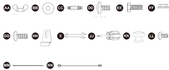
Fig./Img./Abb./Afb./Rys./Obr.6
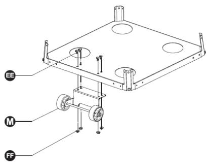
Fig./Img./Abb./Afb./ Rys./Obr.7
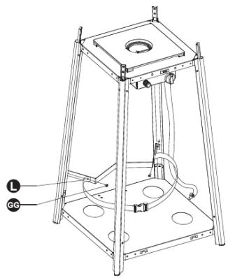
Fig./Img./Abb./Afb./ Rys./Obr.9

Fig./Img./Abb./Afb./ Rys./Obr.8

Fig./Img./Abb./Afb./Rys./Obr.10

Fig./Img./Abb./Afb./ Rys./Obr.11

Fig./Img./Abb./Afb./ Rys./Obr.12

Fig./Img./Abb./Afb./ Rys./Obr.13

Fig./Img./Abb./Afb./ Rys./Obr.14

Fig./Img./Abb./Afb./ Rys./Obr.15

Fig./Img./Abb./Afb./ Rys./Obr.16
natural_image
Technical line drawing of a gas cylinder mounted on a ladder, with an inset showing a close-up of the cylinder (no text or symbols present)Fig./Img./Abb./Afb./ Rys./Obr.17


natural_image
Technical diagram showing mechanical assembly with two views (top and side), no visible text or symbolsFig./Img./Abb./Afb./ Rys./Obr.18
www.cecotec.es


- SOMMAIRE
- Heater stand and location
- Gas requirements
- Leakage test
- INSTRUCTIONS DE SÉCURITÉ
- BEFORE USE
- ASSEMBLY
- Tools needed:
- Components:
- Assembly procedures
- ENGLISH
- Warning
- Note
- OPERATION
- To turn on the heater
- Turning off the heater
- CLEANING AND MAINTENANCE
- Cleaning and maintenance
- Storage
- TROUBLESHOOTING
- TECHNICAL SPECIFICATIONS
- Construction and characteristics
- Specifications
- DISPOSAL OF OLD ELECTRICAL APPLIANCES
- TECHNICAL SUPPORT AND WARRANTY
- PIÈCES ET COMPOSANTS
- Img. 4
- PROBLEEMOPLOSSING
Brand : CECOTEC
Model : ReadyWarm 8900 Outdoor Microclimate
Category : Gas Heating