
5580 - Garage door opener CHAMBERLAIN - Free user manual and instructions
Find the device manual for free 5580 CHAMBERLAIN in PDF.
User questions about 5580 CHAMBERLAIN
0 question about this device. Answer the ones you know or ask your own.
Ask a new question about this device
Download the instructions for your Garage door opener in PDF format for free! Find your manual 5580 - CHAMBERLAIN and take your electronic device back in hand. On this page are published all the documents necessary for the use of your device. 5580 by CHAMBERLAIN.
USER MANUAL 5580 CHAMBERLAIN
AT/BA/BE/BG/CH/CY/CZ/DE/DK/ES/FR/GB/GR/HR/HU/EI/IS/IT/LU/MT/NL/NO/PL/PT/RO/RU/SE/SI/SK/TR/YU
Installation 3-5 12-21
Manager, Regulatory Affairs
THE CHAMBERLAIN GROUP, INC.
845 Larch Ave.
Elmhurst, IL 60126
USA
February 2008

Installation 3-5 12-21
Manager, Regulatory Affairs
THE CHAMBERLAIN GROUP, INC.
845 Larch Ave.
Elmhurst, IL 60126
USA
February, 2008
Start by reading These Import Safety Instructions

Failure to comply with the following instructions may result in serious personal injury or property damage.
- Read these instructions carefully
- The garage door opener is designed and tested to offer reasonable safe service provided it is installed and operated in strict accordance with the instructions in this manual.
These safety alert symbols mean Warning - a personal safety or property damage instruction. Read these instructions carefully.
WARNING: If your garage has no service entrance door, Model 1702E Outside Quick Release must be installed. This accessory allows manual operation of the garage door from outside in case of power failure.

Keep garage door balanced. Sticking or binding doors must be repaired. Garage doors, door springs, cables, pulleys, brackets and their hardware are under extreme tension and can cause serious personal injury. Do not attempt to loose, move or adjust them. Call for garage door service.

Do not wear rings, watches or loose clothing while installing or servicing a garage door opener.
To avoid serious personal injury from entanglement, remove all ropes connected to the garage door before installing the door opener.
Installation and wiring must be in compliance with your local building and electrical codes. Connect the power supply cord only to properly earthed mains.

Lightweight doors of fiberglass, aluminum or steel must be substantially reinforced to avoid door damage. (See page 3.) The best solution is to check with your garage door manufacturer for an opener installation reinforcement kit.

The safety reverse system test is very important. Your garage door MUST reverse on contact with a 40mm obstacle placed on the floor. Failure to properly adjust the opener may result in serious personal injury from a closing garage door. Repeat the test once a month and make any needed adjustments.

This unit should not be installed in a damp or wet space.

Door must not extend over public byway during operation.

The force, as measured on the closing edge of the door, should not exceed 400 N (40kg). If the closing force is more than 400 N, the Protector System must be installed. Do not use the force setting procedure to compensate for a binding or sticking garage door. Excessive force will interfere with the proper operation of the Safety Reverse System or damage the garage door.
Permanently fasten the caution label adjacent to the lighted door control button as a reminder of safe operating procedures.
Disengage all existing garage door locks to avoid damage to garage door.
Install the lighted door control button (or any additional push buttons) in a location where the garage door is visible, at a height of at least 1.5m and out of the reach of children. Do not allow children to operate push button(s) or remote control(s). Serious personal injury from a closing garage door may result from misuse of the opener.
Activate opener only when the door is in full view, free of obstructions and opener is properly adjusted. No one should enter or leave the garage while the door is in motion. Do not allow children to play near the door.
Use manual release only to disengage the trolley and, if possible, only when the door is closed. Do not use the red handle to pull the door open or closed. Disconnect electric power to the garage door opener before making repairs or removing covers.
This product is provided with a power supply cord of special design which, if damaged, must be replaced by a power supply cord of the same type; such a power supply cord may be obtained from your local LiftMaster distributor and must be fitted by a specialist.
Contents
Page
Illustration
Safety Rules 1
Before you Begin 1
Door Types 1
Tools Required 2 2
Hardware Provided 2 3
Completed Installation 2 4
Assembly 2 5-11
Installation 2-4 12-21
Programming your Opener & Remote 4 22
Program your Keyless Entry 5 23
Adjustment 5 24-26
Install the Protector System
(Optional) 5 27
Special Features of the
5580/3780 6 28
Accessories 6 29
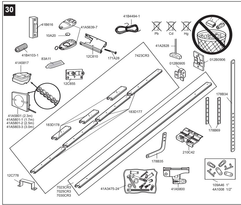
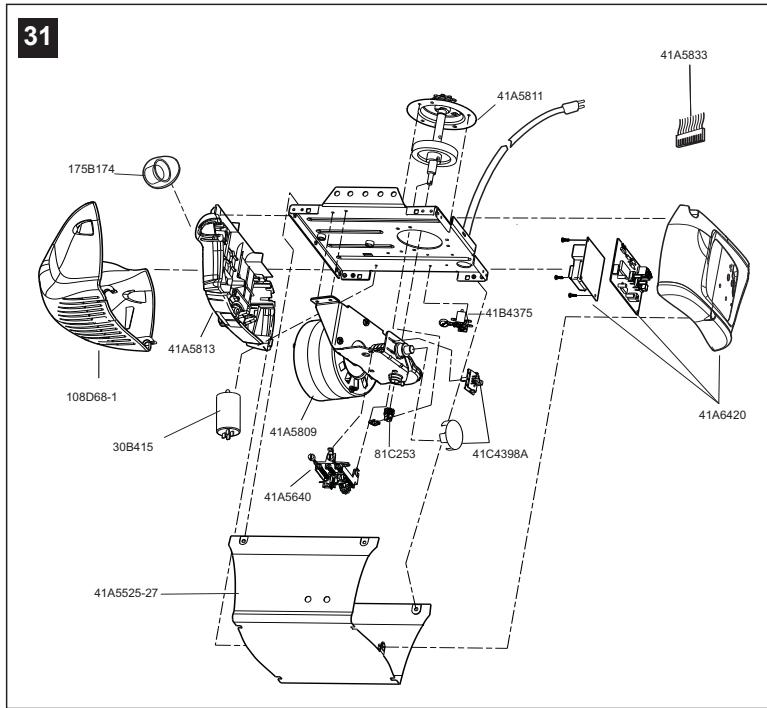
Replacement Parts 6 30-31
Having a Problem? 6-7
Care of your Opener 7
Maintenance of your Operator 7
Operation of your Opener 8
Specifications 8
Before You Begin
- Look at the wall or ceiling above the garage door. The header bracket must be securely fastened to structural supports.
- Do you have a finished ceiling in your garage? If so, a support bracket and additional fastening hardware (not supplied) may be required.
- Depending on your door's construction, you might need a special door arm. See your dealer.
- Do you have an access door in addition to the garage door? If not, Model 1702E Outside Quick Release Accessory is required.
- Determine the type of door and whether the Chamberlain Arm or Protector System is required.
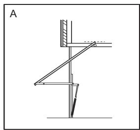
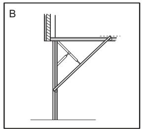
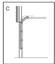
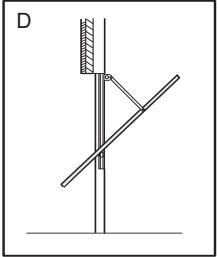
1 Door Types
A. One-Piece Door with Horizontal Track Only
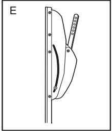
B. One-Piece Door with Horizontal and Vertical Track - Special door arm (E, The Chamberlain Arm™) and The Protector System (29 (9)) are required. See your dealer.
C. Sectional Door with Curved Track - See 20B - connect door arm. The Protector System (29 (9) is required for doors that are over 2.5m in height.
D. Canopy door - Special door arm (E, The Chamberlain Arm™) and The Protector System (29 (9)) are required. See your dealer.
E. The Chamberlain Arm™ for use on door types B and D.
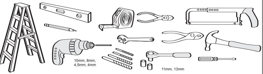
2 Tools Required
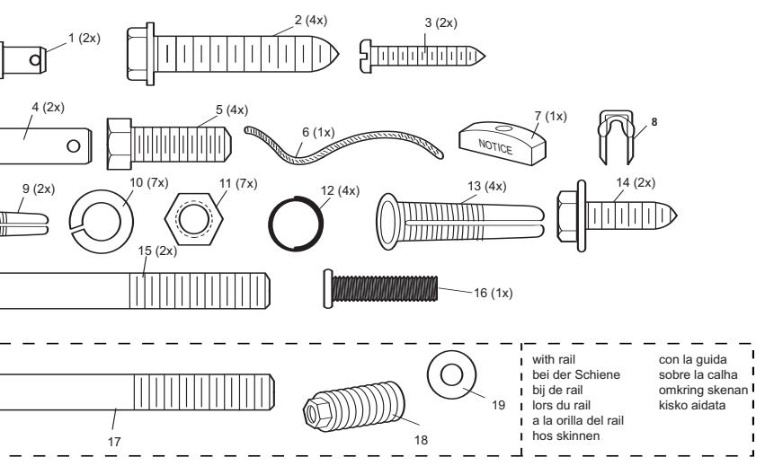
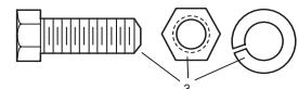
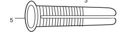
3 Hardware Provided
(1) Clevis Pin
(9) Anchors
(2) Wood Screws
(10) Lock Washer
(3) Screws
(11) Nuts
(4) Clevis Pins
(12) Ring Fastener
(5) Hex Screws
(13) 8mm Anchors
(6) Rope
(14) Sheet Metal Screws
(7) Handle
(15) Carriage Bolts
(8) Insulated Staples
(16) Stop Bolt
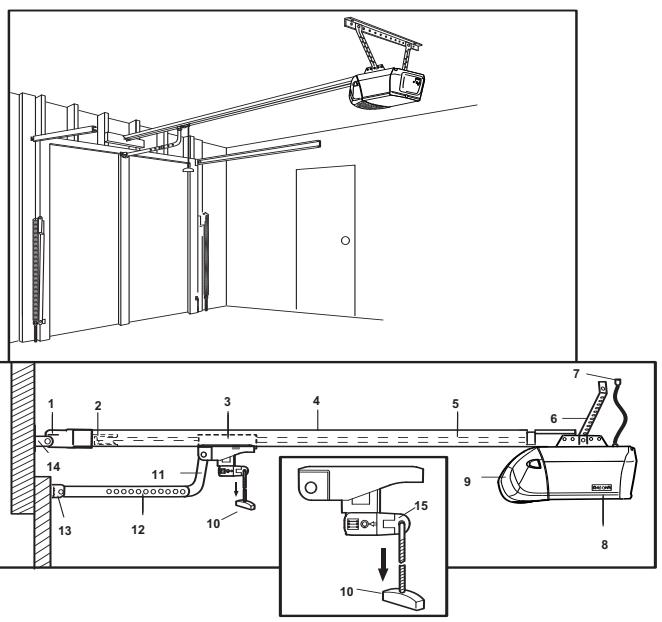
Completed Installation
As you proceed with the assembly, installation and adjustment procedures in this manual, you may find it helpful to refer back to this illustration of a completed installation.
(1)Header Sleeve
(9) Light Lens
(2) Chain Pulley Bracket
(10) Manual Release
(3) Trolley
Rope & Handle
(4) Rail
(11) Curved Door Arm
(5) Chain
(12) Straight Door Arm
(6) Hanging Bracket
(13) Door Bracket & Plate
(7) Power Cord
(14)Header Bracket
(8) Opener
(15) Trolley Release Arm
ASSEMBLY SECTION
IMPORTANT: If you have a canopy or dual track one-piece door, you need to use the instructions packed with The Chamberlain Arm™ Accessory in conjunction with this Owner's Manual when assembling the rail.
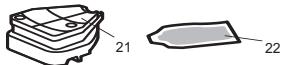
5 Assemble the Rail
NOTE: If your opener came with a one piece rail, proceed to step 8. Grease inside edges of rail sections using grease (1). Place rail pieces (2) on flat surface for assembly. All four rail sections are interchangeable. Slide rail braces (3) onto rail section. Connect rail by sliding rail brace onto next rail section. Tap rail assembly (4) on piece of wood (5) until rail sections are flush. Repeat with remaining rail sections.
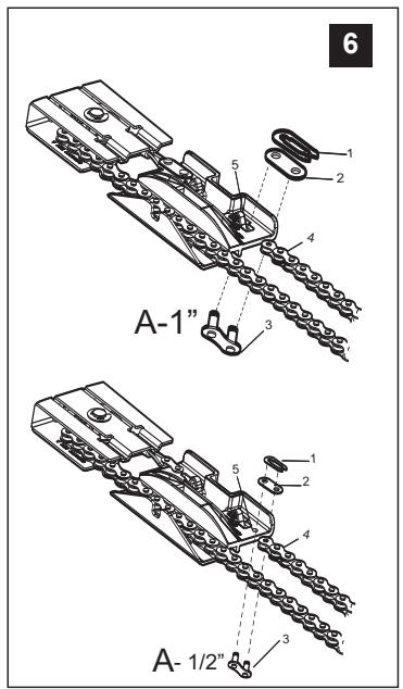
6 Install the Chain
Remove chain from carton and lay chain out on floor (do not allow chain to twist). Push pins of master link bar (3) through chain link (4) and hole in trolley (5).(see picture) Push cap (2) over pins and onto notches. Slide clip-on spring (1) over cap and onto pin notches until both pins are securely locked in place.
7 Insert Chain into Rail & Assemble Header Sleeve
Slide pulley bracket (1) and inner trolley (2) into back (opener end) of rail assembly (3), be sure to insert pulley bracket as shown with arrow (4) pointing toward front (header end) of rail (5). Push bracket toward front (header end) of rail (5). Insert carriage bolt (6) through header sleeve bracket (7). Loosely thread spring nut (8) onto carriage bolt. Insert carriage bolt (6) of header sleeve assembly (7) into bold cut out in pulley bracket (1). Slide header sleeve assembly (7) on to front (header end) of rail (4).
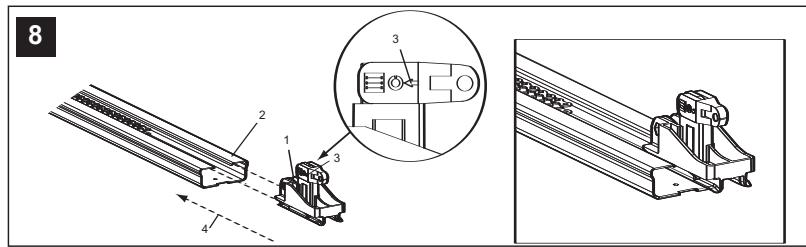
8 Attach Trolley to Rail
Slide outer trolley (1) into rail assembly (2), be sure arrow on trolley (3) is heading in direction of door is heading in direction of door (4). Slide outer trolley down rail until it engages with inner trolley.
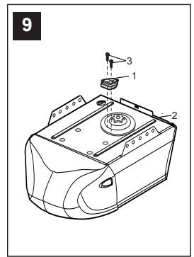
9 Attach Chain Spreader
Attach chain spreader (1) to opener (2) with phillips pan head screws (3).
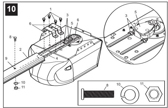
10 Fasten Rail to Opener & Install Chain
Remove four washed bolts (1) from top of opener. Place rail (2) on opener, flush with stops (3) on top of opener. Wrap chain (4) around slot in spreader (5) and over sprocket (6). Push idler pulley bracket assembly toward front of the rail to eliminate excess slack in chain. Align bolt holes on brackets (7) with bolt holes on opener. Secure brackets to opener with previously removed bolts. Tighten bolts securely. The opener sprocket teeth must engage the chain. Insert bolt (8) into trolley stop bolt hole (9) secure with lock washer (10) and nut (11).
CAUTION: Use only those bolts mounted in the top of opener. Use of any other bolts will cause serious damage to opener.
11 Assemble Header Sleeve
Thread spring nut on carriage bolt unit finger tight. Insert a screwdriver tip (1) into one of the slots of the nut ring (2) and brace it firmly against the header sleeve. Place an open end wrench (3) on the square end of the spring nut (4), slightly rotate nut about 1/4 turn clockwise until nut ring (2) is released against header sleeve (5). This sets spring to optimum chain tension. chain may slip off sprocket if chain is too loose. If chain does slip re-tighten spring nut by turing nut clockwise 1/2 turn. Do NOT overtighten chain.
INSTALLATION SECTION
Wear protective goggles when working overhead to protect your eyes from injury.
Disengage all existing garage door locks to avoid damage to the garage door.
To avoid serious personal injury from entanglement, remove all ropes connected to the garage door before installing the opener. It is recommended that the opener be installed 2,1m (7 feet) or more above the floor where space permits.
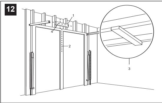
12 Position the Header Bracket
The header bracket must be rigidly fastened to a structural support of the garage. Reinforce the wall or ceiling with a 40mm (1-1/2") board if necessary. Failure to comply may result in improper operation of safety reverse system.
You can attach the header bracket either to the header wall (1) or to the ceiling (3). Follow the instructions which will work best for your particular requirements.
With the door closed, mark the vertical centerline (2) of the garage door. Extend line onto header wall above the door.
Open door to highest point of travel. Draw an intersecting horizontal line (4) on header wall 5cm (2") above high point to provide travel clearance for top edge of door.
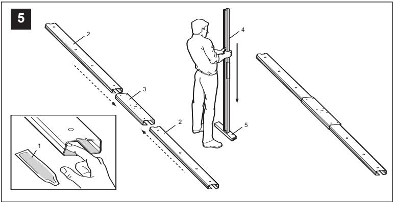
13 Install the Header Bracket
NOTE: Refer to vertical center and horizontal lines created in step 12 for proper placement or header bracket.
A. Wall Mount: Center the bracket (1) on the vertical guideline (2) with the bottom edge of the bracket on the horizontal line (4) (with the arrow pointing toward the ceiling). Mark all of the bracket holes (5). Drill 4,5mm (3/16") pilot holes and fasten the bracket with wood screws (3). For concrete mount, use concrete anchors provided.
B. Ceiling Mount: Extend vertical guideline (2) onto the ceiling. Center the bracket (1) on the vertical mark no more than 150mm (6") from the wall. Make sure the arrow is pointing toward the wall. Mark all of the bracket holes (5). Drill 4,5mm (3/16") pilot holes and fasten the bracket with wood screws (3). For concrete ceiling mount, use concrete anchors (6) provided.
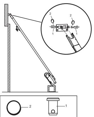
14 Attach Rail to Header Bracket
Position opener on garage floor below the header bracket. Use packing material to protect the cover. Raise rail until holes in the header sleeve and holes in the header bracket align. Join with clevis pin (1). Insert ring fastener (2) to secure.
NOTE: To enable the rail to clear sectional door springs, it may be necessary to lift opener onto a temporary support. The opener must either be secured to a support or held firmly in place by another person.
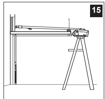
NOTE: A 25mm (1") board (1) is convenient for setting an ideal door-to-rail distance (unless headroom is not sufficient).
Raise the opener onto a stepladder. Open garage door. Place a 25mm (1") board (1) laid flat on the top section of door near the centerline as shown. Rest the rail on the board.
If the raised door hits the trolley, pull down on the trolley release arm to disconnect the inner and outer trolley sections. The trolley can remain disconnected until connecting door arm to trolley is completed.

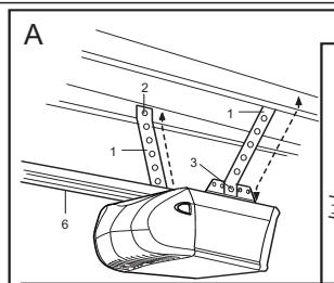
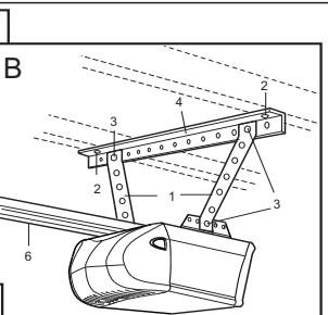
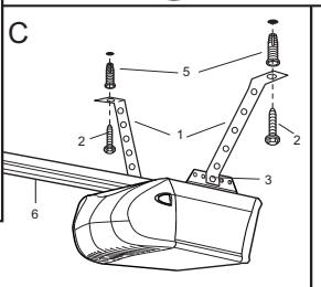
Hang the Opener
The opener must be securely fastened to a structural support of the garage.
Three representative installations are shown. Yours may be different. Hanging brackets (1) should be angled (Figure A) to provide rigid support. On finished ceilings, (Figure B) attach a sturdy metal bracket (not supplied) (4) to a structural support before installing the opener. For concrete ceiling mount, (Figure C), use concrete anchors (5) provided.
On each side of opener measure the distance from the opener to the structural support (or ceiling).
Cut both pieces of the hanging bracket to required lengths. Flatten one end of each bracket and bend or twist to fit the fastening angles. Do not bend at the bracket holes. Drill 4,5mm (3/16") pilot holes in the structural supports (or ceiling). Attach flattened ends of brackets to supports with wood screws (2).
Lift opener and fasten to hanging brackets with screw, lock washer and nut (3). Check to make sure rail is centered over the door. Remove 25mm (1") board. Operate door manually. If door hits the rail, raise header bracket. Use rail grease and lubricate bottom surface of rail (6).

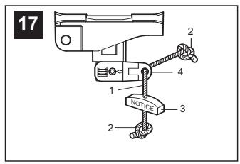
Attach Emergency Release Rope & Handle
Thread one end of rope (1) through hole in top of red handle so "NOTICE" reads right side up as shown (3). Secure with an overhand knot (2). Knot should be at least 25mm (1") from end of the rope to prevent slipping.
Thread other end of rope through hole in release arm of the outer trolley (4). Adjust rope length so that handle is 1,8m (6 feet) above the floor. Secure with an overhand knot.
NOTE: If it is necessary to cut rope, heat seal cut end with a match or lighter to prevent fraying.

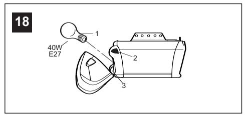
Install Light
Press the release tabs on both sides of lens (2). Gently rotate lens back and downward until the lens hinge is in the fully open position. Do not remove the lens. Install a 40 watt (socket size E27), maximum light bulb (1) in the socket (3) as shown. The light will turn on and remain lit for 2-1/2 minutes when power is connected. After 2-1/2 minutes it will turn off. Reverse the procedure to close the lens.
Replace burned out bulbs with rough service light bulbs.
Connect Electric Power
TO AVOID INSTALLATION DIFFICULTIES, DO NOT RUN THE GARAGE DOOR OPENER UNTIL INSTRUCTED TO DO SO.
Connect the opener to a mains which is properly EARTHED according to the wiring instruction tag attached to power supply cord (and as specified by local code).

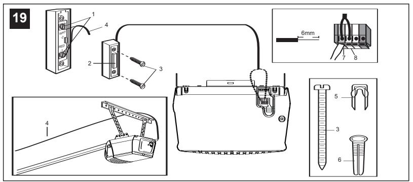
Install Lighted Door Control Button
Locate push buttons where the garage door is visible (at a height of at least of 1,5m), away from door and door hardware and out of the reach of children.
Serious personal injury from a moving garage door may result from misuse of opener. Do not allow children to operate the lighted door control button or remote control transmitter.
Permanently fasten the caution label on the wall near the lighted door control button as a reminder of safe operating procedures.
There are 2 screw terminals (1) on the back of the lighted door control button (2). Strip about 6mm (1/4") of insulation from bell wire (4). Separate wires enough to connect the white/red wire to terminal screw 1 and the white wire to terminal screw 2.
Fasten the lighted door control button to an inside garage wall with sheet metal screws (3) provided. Drill 4mm (5/32") holes and use anchors (6) if installing into drywall. A convenient place is beside the service door and out of reach of children.
Run the bell wire up the wall and across the ceiling to the garage door opener. Use insulated staples (5) to secure wire. The receiver quick connect terminals are located on the back panel of the opener. Connect the bell wire to the terminals as follows: white/red to red (7) and white to white (8).
Operation of the Lighted Door Control Button
Press to open or close the door. Press again to reverse the door during the closing or opening cycle.

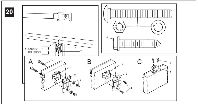
Fasten Door Bracket
If yours is a canopy or dual-track one-piece style garage door, a door arm conversion kit is required. Follow the installation instructions included with the replacement door arm. Exercise care in removing and assembling arm conversion kit. Keep fingers away from the sliding parts.
NOTE: Horizontal and vertical reinforcement is needed for lightweight garage doors.
Sectional and One-Piece Door Installation Procedure:
Door bracket (1) has left and right side fastening holes. Assemble and install the bracket and plate (2) if your installation requires top and bottom fastening holes.
- Center bracket (with or without plate, as required) at the top of inside face of door as shown. Mark holes.
A.Standard Sectional or One-piece doors: locate bracket at inside face of the door.
B. Sectional doors with two horizontal roller channels: 150 - 250mm below the top of the door.
2. A. Wooden doors
Drill 8mm holes (5/16") and fasten the door bracket with nut, lock washer, and carriage bolt (3) or use wood screws.
B. Sheet metal doors
Fasten with sheet metal screws (4).
C. One-piece door optional
Fasten with sheet metal screws (4).

NOTE: For one-piece doors, do not connect door arm to trolley before adjusting limits. Failure to follow instructions may result in damage to door. See below.
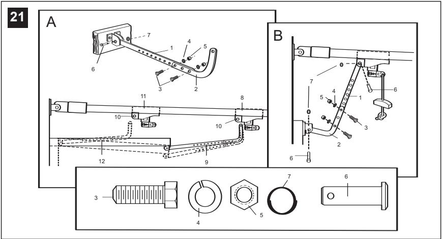
A. ONE-PIECE DOOR INSTALLATION:
Connect straight door arm (1) and curved door arm sections (2) to obtain the longest possible length with hardware (3, 4 & 5). With door closed, connect straight door arm section to door bracket with a clevis pin (6). Secure with a ring fastener (7).
Before connecting door arm to trolley, adjust travel limits. Limit adjustment screws are located on left side panel.
Open Door Adjustment: Decrease up limit. Turn up limit adjustment screw counterclockwise 4-1/2 turns.
Press door control button. Trolley will travel to full open position (8). Manually raise door to open position (parallel to floor) and lift door arm (9) to trolley. The arm should touch trolley just in back of door arm connector hole (10) as shown in solid line drawing. Increase up limit if necessary. One full turn equals 7,5cm (3") of door travel.
Closed Door Adjustment: Decrease down limit. Turn down limit adjustment screw clockwise 4 complete turns.
Press door control button. Trolley will travel to full closed position (11). Manually close door and lift door arm (12) to trolley. The arm should touch trolley just ahead of door arm connector hole (10) as shown in dotted line drawing. Decrease down limit if necessary. One full turn equals 7,5cm (3") of door travel.
Connect Door Arm to Trolley: With door closed, connect curved arm to trolley with remaining clevis pin. Secure with ring fastener. NOTE: Lift door slightly to make connection if necessary.
Run opener through a complete travel cycle. If door has a slight "backward" slant in full open position, decrease up limits until door is parallel to floor.
B. SECTIONAL DOOR INSTALLATION:
Connect according to Figure B, then proceed to Step 24.
Activate the opener only when door is in full view, free of obstruction and properly adjusted. No one should enter or leave garage while door is in motion. Do not allow children to operate push button(s) or remote(s). Do not allow children to play near the door.
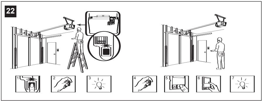
Your garage door opener receives and remote control transmitter are set to a matching code. If you purchase additional remote controls, the garage door opener must be programmed to accept the new remote code.
Program the Receiver to Match Additional Remote Control Codes:
Using the "LEARN" Button
- Press and release the "learn" button on the motor unit. The learn indicator light will glow steadily for 30 seconds (1).
- Within 30 seconds, press and hold the button on the hand-held remote that you wish to operate your garage door (2).
- Release the button when the motor unit light blinks. It has learned the code. If light bulb is not installed, two clicks will be heard (3).
Using the Multi-Function Door Control (optional):
- Press and hold the button on the hand-held remote that you wish to operate your garage door (4).
- While holding the remote button, press and hold the LIGHT button on the Multi-Function Door Control (5).
- Continue holding both buttons while you press the push bar on the Multi-Function Door Control (all three buttons are held) (6).
- Release buttons when the motor unit light blinks. It has learned the code. If light bulb is not installed, two clicks will be heard (7). Now the opener will operate when the remote control push button is pressed. If you release the remote control push button before the opener lights flash, the opener has not learned the code.
To Erase all Remote Control Codes
To deactivate any unwanted remote, first erase all codes:
Press and hold the "learn" button on motor unit until the learn indicator light goes out (approximately 6 seconds). All previous codes are now erased. Reprogram each remote or keyless entry you wish to use.
3-Channel Remote:
If provided with your garage door opener, the large button is factory programmed to operate it. Additional buttons on any rolling code 3-channel remote or mini-remote can be programmed to operate other rolling code garage door openers or gates.


Program your Keyless Entry (optional)
Activate the opener only when door is in full view, free of obstruction and properly adjusted. No one should enter or leave garage while door is in motion. Do not allow children to operate push button(s) or remote(s). Do not allow children to play near the door.
NOTE: Your new Keyless Entry must be programmed to operate your garage door opener.
Program the Receiver to Match Additional Remote Control Code Using the "LEARN" Button:
- Press and release the "learn" button (1) on opener. The learn indicator light will glow steadily for 30 seconds.
- Within 30 seconds, enter a four-digit personal identification number (PIN) of your choice on the keypad (2), then press and hold the ENTER button.
- Release the button when the opener light blinks (3). It has learned the code. If light bulb is not installed, two clicks will be heard.
NOTE: This method requires two people if the Keyless Entry is already mounted outside the garage.
Using the Multi-Function Door Control (optional):
- Enter a four-digit personal identification number (PIN) of your choice on the keypad, then press and hold ENTER (4).
- While holding the ENTER button, press and hold the LIGHT button on the Multi-Function Door Control (5).
- Continue holding the ENTER and LIGHT buttons while you press the push bar on the Multi-Function Door Control (all three buttons are held) (6).
- Release buttons when the opener light blinks. It has learned the code. If light bulb is not installed, two clicks will be heard (7).

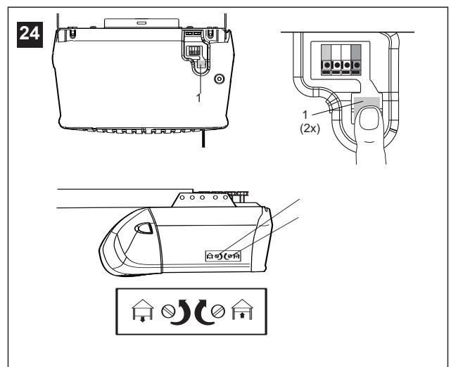
Limit Adjustment
Run the opener through a complete travel cycle. Limit adjustments are not necessary when the door opens and closes completely and doesn't reverse unintentionally in the fully closed position.
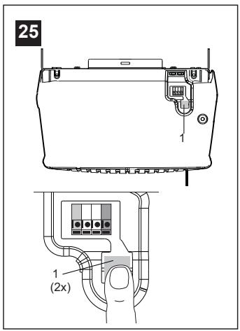
Locate the button (1) on the back panel of motor unit. Push the button twice to enter into Force Setting Mode.
NOTE: Repeated operation of the opener during adjustment procedures may cause motor to overheat and shut off. Allow a 15 minute cooling period after 5 continuous operations of the opener. Read the following carefully before proceeding to Force Adjustment. Use a screwdriver to make limit adjustments.
If Door Doesn't Open Completely but Opens at Least 1,5m (5 feet): Increase up travel. Turn the up limit adjustment screw (3) clockwise. One turn equals 5cm (2") of travel.
If door does not open at least 1,5m (5 feet). Adjust force, see Force Adjustment: Place the opener into the Force Adjustment Mode, see Force Adjustment.
If Door Doesn't Close Completely: If door arm is at maximum length, increase down travel. Turn down limit adjustment screw (2) counterclockwise. One turn equals 5cm (2") of travel. If the door still will not close completely, the header bracket is positioned too high.
If Opener Reverses in Fully Closed Position: Decrease down travel. Turn down limit adjustment screw (2) clockwise. One turn equals 5cm (2") of travel.
If Door Reverses when Closing and there is no Interference to Travel Cycle: Test door for binding. Pull manual release handle. Manually open and close door. If door is binding, call a door serviceman. If door is not binding or unbalanced, place the opener into the Force Setting Mode, see Force Settings.
PROCEED TO STEP 25 "FORCE SETTINGS" TO COMPLETE STEP 24 "LIMIT ADJUSTMENT". Forces must be learned in order for limit adjustments to operate properly.

Force Settings
The force, as measured on the closing edge of the door, should not exceed 400N (40kg). If the closing force is measured to more than 400N, the Protector System must be installed. See step 27.
The force setting button is located on the back panel of the motor unit. The force setting regulates the amount of power required to open and close the door. If the forces are too light, door travel may be interrupted by nuisance reversals.
Locate the button (1) on the back panel of motor unit. Push the button twice to enter into Force Setting Mode. The LED (Indicator Light) will flash. Push the wall control or the programmed remote control that was shipped with your opener. The door will travel to either the OPEN or CLOSE position. Push the button again, the door will travel to the opposite position. Push the button again if the LED is still blinking.
The door must travel through a complete cycle UP and DOWN in order for the force to be set properly. If the unit reverses before it reaches the Open or Close Limit repeat the process. The LED (indicator light) will stop flashing when the force has been learned.
Note: If unable to set limits return to section 24.


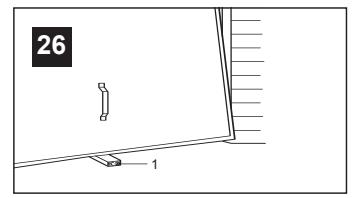
Test the Safety Reverse System
The safety reverse system test is important. Garage door must reverse on contact with a 40mm obstacle laid flat on the floor. Failure to properly adjust opener may result in serious personal injury from a closing garage door. Repeat test once a month and adjust as needed.
Procedure: Place a 40mm obstacle (1) laid flat on the floor under the garage door. Operate the door in the down direction. The door must reverse on the obstruction. If the door stops on the obstruction, it is not traveling far enough in the down direction. Increase the down limit by turning down limit adjustment screw counterclockwise 1/4 turn. Repeat test.
When the door reverses on the 40mm obstacle, remove the obstruction and run the opener through a complete travel cycle. Door must not reverse in closed position. If it does, adjust Limits and Force and repeat safety reverse test.
Test that the door will not fully open when a 20kg weight is added to the bottom of the door.

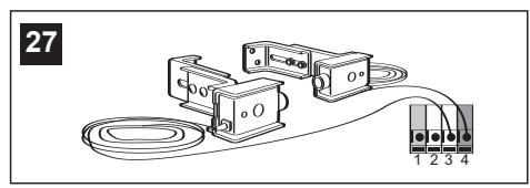
Install the Protector System™
(See accessories)
Install this accessory for all installations on Canopy doors, 1 piece dual track doors, doors over 2.5m and when the closing force as measured on the bottom of the door is over 400N (40kg)
After opener has been installed and adjusted, The Protector System™ accessory can be installed. Instructions are included with this accessory.
The Protector System™ provides an additional measure of safety against a small child being caught under a garage door. It uses an invisible beam which, when broken by an obstruction, causes a closing door to open and prevents an open door from closing and is strongly recommended for homeowners with young children.
Note: The opener will automatically detect the protector system when it is installed. The opener will not close unless the sensors are aligned.
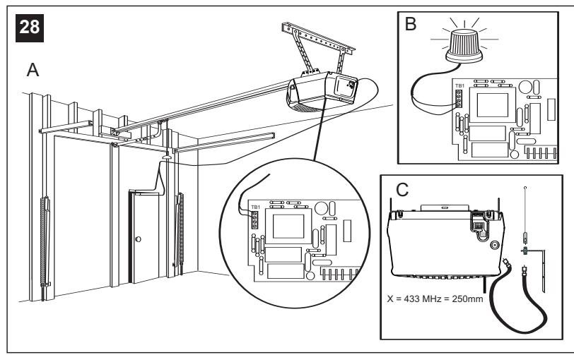
A. Door within a door connection
Disconnect opener from power!
Remove cover. Locate auxiliary terminal block (TB1) on the control board. Remove jumper from terminal leads 1 and 2 (not shown). Replace with contact switch leads as shown.
B. Flashing light connection
The flashing light can be installed anywhere. Connect light leads to terminals 3 and 4 on the terminal block.
C. Coaxial antenna adapter
A coaxial antenna connection can be used if the transmitter range is too short. Cut off the existing antenna. Use standard coax cable and connector. Strip off end of insulation to "X" dimension.
433 MHz: X = 250 ~mm . Reposition antenna.
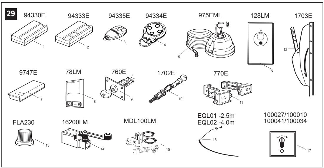
29 Accessories
(1) Model 94330E
Single-Function Remote Control
(2) Model 94333E
3-Function Remote Control
(3) Model 94335E
3-Function Mini Remote Control
(4) Model 94334E
4-Function Mini Remote Control
(5) Model 975EML
Laser Garage Parking Assist
(6) Model 128LM
2-Function Wireless Wall Control
(7) Model 9747E
Keyless Entry System
(8) Model 78LM
Multi-Function Door Control Panel
(9) Model 760E
Outside Keylock
(10) Model 1702E
Outside Quick Release
(11) Model 770E
The Protector System™
(12) Model 1703E
The Chamberlain Arm™
(13) Model FLA230
Flashing Light Kit
(14) Model 16200LM
Pedestrian Door Switch
(15) Model MDL100LM
Mechanical Door Latch Kit
(16) Model EQL01
Door Handle Quick Release - 2.5m
Model EQL02
Door Handle Quick Release - 4.0m
(17) Model 100027
1-Position Key Switch (Flush Mount - 100010)
Model 100041
2-Position Key Switch (Flush Mount - 100034)
WIRING INSTRUCTIONS FOR ACCESSORIES
Keyless Entry System - To opener terminals: Red-1 and White-2
Outside Keylock - To opener terminals: Red-1 and White-2
System^ - To opener terminals: White-2 and Black-3
Door Control Panel - To opener terminals: Red-1 and White-2


Replacement Parts
HAVING A PROBLEM?
-
Opener doesn't operate from either door control or remote:
-
Does the opener have electric power? Plug lamp into outlet. If it doesn't light, check the fuse box or the circuit breaker. (Some outlets are controlled by a wall switch.)
- Have you disengaged all door locks? Review installation instruction warnings on page 1.
- Is there a build-up of ice or snow under door? The door may be frozen to ground. Remove any obstruction.
- The garage door spring may be broken. Have it replaced.
-
Repeated operation may have tripped the overload protector in the motor. Wait 15 minutes. Try again.
-
Opener operates from remote but not from door control:
-
Is door control button lit? If not, remove the bell wire from the opener terminals. Short the red and white terminals by touching both terminals at the same time with a piece of wire. If the opener runs, check for a faulty wire connection at the door control, a short under the staples, or a broken wire.
-
Are wiring connections correct? Review page 3.
-
Door operates from door control but not from remote:
-
Check battery. Replace battery if necessary.
- Is the light at the wall control flashing? Press button with key-symbol to unlock the opener against remote controls.
- Is the receiver LED flashing at the back-side of the opener when the transmitter is pressed? The opener receiver must re-learn the remote control code. Follow the instructions on page 4.
- If you purchased a new remote control then check at carton of remote control for compatibility or call the Service Hotline.
4. Remote has short range:
Is battery installed? If needed, change the battery.
- Change the location of the remote control on the car.
- A metal garage door, foil-backed insulation or metal siding will reduce the transmission range.
- Use outside coaxial antenna adapter to move antenna.
-
Door reverses for no apparent reason and opener light doesn't blink:
-
Is something obstructing the door? Pull manual release handle. Operate door manually. If it is unbalanced or binding, call for professional garage door service.
- Clear any ice or snow from garage floor area where garage door closes.
- Review Force Settings. Open and close the door in learn mode for several (3-5) consecutive cycles to allow the operator to adjust to inconsistent doors.
- If door reverses in FULLY CLOSED position, re-learn travel limits. Repeat safety reverse test after adjustment is complete.
The need for occasional adjustment of the force and limit settings is normal. Weather conditions in particular can affect door travel.
- Door reverses for no apparent reason and opener light blinks for 5 seconds after reversing:
Check The Protector System™ (if you have installed this accessory). If the light is blinking, correct alignment.
Note: Continuously holding down the door control button will allow the door to close if the protector system is not properly aligned. The transmitter will not close the door. The opener lights will blink.
- Opener noise is disturbing in living quarters of home:
If operational noise is a problem because of proximity of the opener to the living quarters, Vibration Isolator Kit 41A3263 can be installed. This kit was designed to reduce the "sounding board effect" and is easy to install.
-
The garage door opens and closes by itself:
-
Delete all remote controls and reprogram.
- Make sure remote push button is not stuck "on".
- Disconnect all push buttons or key switches attached and wait one day.

9. Door stops but doesn't close completely:
Review Limit Adjustment section.
Repeat safety reverse test after any adjustment of door arm length, close force or down limit.
10. Door opens but won't close:
- Check The Protector System™ (if you have installed this accessory). If the light is blinking, correct alignment.
- If opener light does not blink and it is a new installation, check the down force.
Repeat the safety reverse test after the adjustment is complete.
11. Opener light does not turn on:
Replace light bulb (40 Watts maximum). Replace burned out bulbs with rough service light bulbs.
12. Opener light does not turn off:
There may be a defective earth at the ceiling or wall receptacle. The unit must be earthed.
13. Opener strains or reversed during opening:
Door may be unbalanced or springs are broken. Close door and use manual release rope and handle to disconnect trolley. Open and close door manually. A properly balanced door will stay in any point of travel while being supported entirely by its springs. If it does not, call for professional garage door service to correct the problem. Do not change force settings.
14. Opener motor hums briefly, then won't work:
- Garage door springs are broken. SEE ABOVE.
- If problem occurs on first operation of opener, door is locked. Disable door lock. If chain was removed and reinstalled, the motor may be out of phase. Remove chain; cycle motor to down position. Observe drive sprocket. When it turns in clockwise direction and stops in down position, re-install chain.
Repeat safety reverse test after adjustment is complete.
15. Opener won't activate due to power failure:
- Pull manual release rope and handle down and back to disconnect trolley. Door can be opened and closed manually. When the power is restored, pull the manual release handle straight down. The next time the opener is activated, the trolley will reconnect.
- The Outside Quick Release accessory (if fitted) disconnects the trolley from outside the garage in case of power failure.
CARE OF YOUR OPENER
When properly installed, opener will provide high performance with a minimum of maintenance. The opener does not require additional lubrication.
Limit Adjustments: These adjustments must be checked and properly set when opener is installed. Only a screwdriver is required. Weather conditions may cause some minor changes in the door operation, requiring some re-adjustments, particularly during the first year of operation.
Refer to the limit adjustments and force settings on page 5. Follow the instructions carefully and repeat the safety reverse test after any adjustment.
Remote Control Transmitter: The portable remote control may be secured to a car sun visor with the clip provided. Additional remotes can be purchased at any time for use in all vehicles using garage. Refer to Accessories. Any new remotes must be set to the same code as the original remote.
Remote Control Battery: The lithium batteries should produce power for up to 5 years. If transmission range lessens, check the battery.
To Change Battery: To replace batteries, use the visor clip or screwdriver blade to pry open the case. Insert batteries positive side up. To replace cover, snap shut along both sides. Do not dispose of the old battery with household waste. Take batteries to a proper disposal center.
MAINTENANCE OF YOUR OPENER
Once a Month:
- Repeat safety reverse test. Make any necessary adjustments.
- Manually operate door. If it is unbalanced or binding, call for professional garage door service.
- Check to be sure door opens and closes fully. Adjust Limits and/or Force settings if necessary.
Once a Year:
- Oil door rollers, bearings and hinges. The opener does not require additional lubrication. Do not grease the door tracks.
- GREASE THE RAIL AND THE TROLLEY.
Your opener can be activated by any of the following devices:
- The Lighted Door Control Button. Hold the button down until door starts to move.
- The Outside Keylock or Keyless Entry System (if you have installed either of these accessories).
- The Remote Control Transmitter. Hold the push button down until the door starts to move.
Opening the Door Manually:
Door should be fully closed if possible. Weak or broken springs could allow an open door to fall rapidly. Property damage or serious personal injury could result.
The door can be opened manually by pulling the release handle down and back (toward the opener). To reconnect the door, pull the release handle straight down.
Do not use the manual release handle to pull the door opener or closed.
When the Opener is Activated by Remote Control or Lighted Door Control Button:
- If open, the door will close. If closed, the door will open.
- If closing, the door will stop.
- If opening, the door will stop.
- If the door has been stopped in a partially open or closed position, it reverse direction.
- If an obstruction is encountered while closing, the door will reverse.
- If an obstruction is encountered while opening, the door will reverse briefly.
- The optional Protector System™ is automatically detected and an invisible beam which, when broken by an obstruction, causes a closing door to open and prevents an open door from closing. It can be overridden only by the outside key lock, keyless entry system or door control button. It is STRONGLY RECOMMENDED for homeowners with young children.
Allow a 15 minute cooling period after 5 continuous operations of the opener.
The opener light will turn on: 1. when opener is initially plugged in;
- when the power is interrupted; 3. when the opener is activated.
The light turns off automatically after 2-1/2 minutes. Bulb size is 40 Watts maximum.
GARAGE DOOR OPENER WARRANTY
Chamberlain GmbH warrants to the first retail purchaser of this product (3780 or 5580) that the product shall be free from any defect in materials and/or workmanship for a period of 24 full months (2 years) from the date of purchase. Upon receipt of the product, the first retail purchaser is under obligation to check the product for any visible defects.
Conditions: The warranty is strictly limited to the reparation or replacement of the parts of this product which are found to be defective and does not cover the costs or risks of transportation of the defective parts or product.
This warranty does not cover non-defect damage caused by unreasonable use (including use not in complete accordance with Chamberlain's instructions for installation, operation and care; failure to provide necessary maintenance and adjustment; or any adaptations of or alterations to the products), labor charges for dismantling or reinstalling of a repaired or replaced unit or replacement batteries.
A product under warranty which is determined to be defective in materials and/or workmanship will be repaired or replaced (at Chamberlain's option) at no cost to the owner for the repair and/or replacement parts and/or product. Defective parts will be repaired or replaced with new or factory rebuilt parts at Chamberlain's option.
If, during the warranty period, the product appears as though it may be defective, contact your original place of purchase.
This warranty does not affect the purchaser's statutory rights under applicable national legislation in force nor the purchaser's rights against the retailer arising from their sales/purchase contract. In the absence of applicable national or EU legislation, this warranty will be the purchaser's sole and exclusive remedy, and neither Chamberlain nor its affiliates or distributors shall be liable for any incidental or consequential damages for any express or implied warranty relating to this product.
No representative or person is authorized to assume for Chamberlain any other liability in connection with the sale of this product.
SPECIFICATIONS
Max.Pull Force. 800N
Rated Power. 400 W
Motor
Type............Permanent split capacitor
Speed 1500 rpm
Volts. 230-240 Volts AC-50Hz Only
Noise level. 60dB
Drive Mechanism
Gears. 16:1 worm gear reduction
Drive ....Chain with two-piece trolley on steel rail.
Length of Travel............Adjustable to 2,3m (7-1/2 feet)
Travel Rate 96-135mm (3,8"-5,3") per second
Lamp............On when door starts, off 2-1/2 minutes after stop.
Door Linkage ............Adjustable door arm. Pull cord trolley release.
Safety
Personal ...Push button stop in UP and DOWN direction. Automatic force reversal in UP and DOWN direction.
Electronic............Automatic force adjustments.
Electrical............Motor overload protector and low voltage push button wiring.
Limit Device.....Circuit actuated by limit nut.
Limit Adjustment............Screwdriver adjustment on side panel.
Start Circuit............Low voltage push button circuit.
Dimensions
Length (Overall).....3,1m (122-1/2")
Headroom Required .........30mm
Hanging Weight. 14,5 kg (32 lb)
Receiver
Memory Registers ....8
Keypad Code Memory.....1
SPECIAL NOTE: Chamberlain strongly recommends that the protector system be installed on all garage door openers.
Declaration of Conformity

The undersigned, hereby declare that the equipment specified, and all accessories, conforms to the Directives and Standards stated.
Model:
5580,3780
2004/108/EC
2006/95/EC
1999/5/EC
EN55014-1 (2000), EN55014-2 (1997), EN61000-3-2 (2000), EN61000-3-3
(1995), EN 301 489-3 (V1.3.1), EN 300 220-3 (V1.1.1), EN60335-1 (1994), and EN60335-2-95 (2004)
Declaration of Incorporation
A power door operator, in combination with a Garage Door must be installed and maintained according to all the Manufacturer's instructions, to meet the provisions of EN12453, EN13241-1 and Machinery Directive, 89/392/EEC.

B.P.Kelkhoff
Manager, Regulatory Affairs
THE CHAMBERLAIN GROUP, INC.
845 Larch Ave.
Elmhurst, IL 60126
USA
February, 2008
BEGYND MED AT LAESE DISSE VIGTIGE SIKKERHEDSBESTEMMELSER


4 Faerdig installation
(5) Model 975EML Laserparker
(6) Model 128LM 2-Kanal fjernstyring
(7) Model 9747E Abningssystemumennagle
(8) Model 78LM Multikontrolpanel til port
(9) Model 760E Udendørs Iås
Manager, Regulatory Affairs
THE CHAMBERLAIN GROUP, INC.
845 Larch Ave.
Elmhurst, IL 60126
USA
February, 2008
Manager, Regulatory Affairs
THE CHAMBERLAIN GROUP, INC.
845 Larch Ave
Elmhurst, IL 60126
USA
February, 2008
APXIETIABAZONTA TOYI NAPAKATI ZHMANTIKOYKANONEA AAOYXPHEHS

Mn oumuoppwon m TIC napakatw obnyiec mnopei va exei aov anotelεσa oobapo npoosniok tpaumatioo n nepiouiakn φθopa.
iabaoTe autou tou eioous tic oyniec npoox.
O napw unxaviouc ykapaonopacexei oxdeltaaotei kai dokijaotei wotv npoopeei aoepaaln aeoyika nlaiae uyn npounoecn otixei tonoetnei kai xpnoiponoieitai e auotnpn oupwvia e tounapakaw kavovcs aopaaeias.

Ta ouoBla nou 8eTne unObnawovu Npoox- oynia oxetikn e aopaleia n npoiouiak n othopa. Aiaaote autou tou eiooc tic onyiec m npoox.
Ipoox: Av to ykapac z aoc dev exei bongntik npota npenti va xpnoimoine o Exwepikoc Mxavioos Taxiac Aneueuepomega, movteo un'apitou 1702E. To eaptnua auto eipnpen tnv ano eew xiepkivn Tneitoupyia nC ykapaonoptac oe nepittwn diakomnc pEuatoC.

Aiatnpeite Tny ykapaconopota 100zuyioevn. IopTeC nou kollave epika n teaiw npertie va
IPOF PAMMATI TE TO YTHMA EIOO OY
XΩPIΣ KAEIΔI .5-6 .23
PYOMIeH 6 24-26
ERKATAZTAH TOY YETHMATOIPOZTAIAZ
(Плобайергий) 6 27
EIAIKA XAPAKTHPIETIKA TOY
5580/3780 7 28
AEEZOYAP 7 29
Avtaaakiká 7. 30-31
IIPOBAHMATA 7-8
ΦPONTIà TOY
MHXANIEMOY ANOIIMATO8
\SYNTHPHESH TOY
MHXANIEMOY ANOIIMATO8
XPHSEH TOY
MHXANIEMOY ANOIIMATOI 8-9
IPOAIAPAEU 9
INPIN APXIETE
- Eλέγειτε tov toixo ὡ η την oρού πάνω πάστο την γκαραζόπορτα. H βάση κεφαλής πρέπειν α εἰναι ασφαλώς συνδεδεμένη με τα δομίαστοιχεία.
- Eav to ykapac oac exe1 opoyn e neevduon iowc va xpeiazetai va xpnouonoiote nlaio unooTnpicn cai npo0e ta eapntma t npo0e0nc (dEv ouuepilauabovotai).
- Avaloya mV kataakeun mC iowc va xpeiaotheiE iDko bpaxlova npotaac. Zmuouauteite tonpoumthetautn oac.
- Exi to ykapac, oac bonthetaiknpota ektoc ano tnv ykapazopta; Av oxi, toe anaiteitai kal o EeWtepikoc Mxaviooc Taxiae Aneauepomega, movteo un' aptouov 1702E.
- Kaθopiστε tov τύπο τής πόρτας και ἀν ελέγξετον αν απαίτειται βραχονας Chamberlain ἡ Protector System.
1 TYIIO IIOPTΩN
(5) Movéλo 975EML Laser Garage Parking Assist
(6) Movéλo128LM 2-Function Wireless Wall Control
Manager, Regulatory Affairs
THE CHAMBERLAIN GROUP, INC.
845 Larch Ave., Elmhurst, IL 60126, USA
February, 2008


A Anything's done.
A thing's done.
A thing's done.
A thing's done.
Manager, Regulatory Affairs
THE CHAMBERLAIN GROUP, INC.
845 Larch Ave.
Elmhurst, IL 60126
USA
February, 2008
Les disse viktige sikkerhetsreglene for du begyinner


Dersom instruktjoneicine ffolges,kan det resultere i alvorlig personskade ellr skade pa eiendom.
Installer "The ProtectorTM"
(Se ekstrautstyr)
(5) Modell 975EML Laser Garage Parking Assist
VEDLIKEHOLD AV APNEREN
Vedlikehold én gang i帽子en:
- Gjenta testen av sikkerhetsreverseringen. Foreta nødvendige justeringer.
- Betjen porten manuelt. Hvis den er i ubalanse eller er treg, bør du kontakte et serviceverksted.
- Kontroller at porten apner og lukker seg fullstendig. Juster grensene og/eller kraften hvis det er nødvendig.
Manager, Regulatory Affairs
THE CHAMBERLAIN GROUP, INC.
845 Larch Ave.
Elmhurst, IL 60126
USA
February, 2008

Manager, Regulatory Affairs
THE CHAMBERLAIN GROUP, INC.
845 Larch Ave.
Elmhurst, IL 60126
USA
February, 2008
The safety reverse system test is important. Garage door must reverse on contact with a 40mm obstacle laid flat on the floor. Failure to properly adjust opener may result in serious personal injury from a closing garage door. Repeat test once a month and adjust as needed.
Manager, Regulatory Affairs
THE CHAMBERLAIN GROUP, INC.
845 Larch Ave
Elmhurst, IL 60126
USA
February, 2008

Installation 2-4 12-21
Kodprogrammering 4 22
C. Koaxialantennadapter
(5) Modell 975EML Laser Garage Parking Assist
(6) Modell 128LM 2-funktions fjärkrontroll
(7) Modell 9747E Kodlås
2004/108/EC
2006/95/EC
1999/5/EC
EN55014-1 (2000), EN55014-2 (1997), EN61000-3-2 (2000), EN61000-3-3 (1995), EN 301 489-3 (V1.3.1), EN 300 220-3 (V1.1.1), EN60335-1 (1994), och EN60335-2-95 (2004)
Manager, Regulatory Affairs
THE CHAMBERLAIN GROUP, INC.
845 Larch Ave.
Elmhurst, IL 60126
USA
February, 2008


Laser Garage Parking Assist
(6) Malli 128LM
Manager, Regulatory Affairs
THE CHAMBERLAIN GROUP, INC.
845 Larch Ave.
Elmhurst, IL 60126
USA
February, 2008

Abbildunger
3780/5580

Figures
3780/5580

Illustrat
3780/5580

Illustrat
3780/5580

Illustrac
3780/5580

xμat
3780/5580

Illustraz
3780/5580

Illustras
3780/5580

Afbeeld
3780/5580

Figuras
3780/5580

Bild.
3780/5580

Kuvat
3780/5580

C
ATI/BAI/BE/BG/CHCY/CZDE/DKES/ E/FRGR/HRJHUE/SUSL/TUNLANT/L NO/PLT/PRO/RUE/SSK/TRY/U


14
16

CHAMBERLAIN
LiftMaster ™
PROFESSIONAL
Instructions - Garage Door Operator Model 5580A-2GB
Start by reading These Import Safety Instructions


Failure to comply with the following instructions may result in serious personal injury or property damage.
- Read these instructions carefully
- The garage door opener is designed and tested to offer reasonable safe service provided it is installed and operated in strict accordance with the instructions in this manual.
These safety alert symbols mean Caution - a personal safety or property damage instruction. Read these instructions carefully.
WARNING: If your garage has no service entrance door, Model 1702E Outside Quick Release must be installed. This accessory allows manual operation of the garage door from outside in case of power failure.

Keep garage door balanced. Sticking or binding doors must be repaired. Garage doors, door springs, cables, pulleys, brackets and their hardware are under extreme tension and can cause serious personal injury. Do not attempt to loose, move or adjust them. Call for garage door service.

Do not wear rings, watches or loose clothing while installing or servicing a garage door opener.

To avoid serious personal injury from entanglement, remove all ropes connected to the garage door before installing the door opener.

Installation and wiring must be in compliance with your local building and electrical codes. Connect the power supply cord only to properly earthed mains.

Lightweight doors of fiberglass, aluminum or steel must be substantially reinforced to avoid door damage. (See page 4.) The best solution is to check with your garage door manufacturer for an opener installation reinforcement kit.

The safety reverse system test is very important. Your garage door MUST reverse on contact with a 40mm obstacle placed on the floor. Failure to properly adjust the opener may result in serious personal injury from a closing garage door. Repeat the test once a month and make any needed adjustments.

This unit should not be installed in a damp or wet space.

Door must not extend over public byway during operation.

The force, as measured on the closing edge of the door, should not exceed 400 N (40kg). If the closing force is more than 400 N, the Protector System must be installed. Do not use the force setting procedure to compensate for a binding or sticking garage door. Excessive force will interfere with the proper operation of the Safety Reverse System or damage the garage door.

Permanently fasten the caution label adjacent to the lighted door control button as a reminder of safe operating procedures.

Disengage all existing garage door locks to avoid damage to garage door.
Install the lighted door control button (or any additional push buttons) in a location where the garage door is visible, at a height of at least 1.5m and out of the reach of children. Do not allow children to operate push button(s) or remote control(s). Serious personal injury from a closing garage door may result from misuse of the opener.
Activate opener only when the door is in full view, free of obstructions and opener is properly adjusted. No one should enter or leave the garage while the door is in motion. Do not allow children to play near the door.
Use manual release only to disengage the trolley and, if possible, only when the door is closed. Do not use the red handle to pull the door open or closed.
7 Disconnect electric power to the garage door opener before making repairs or removing covers.
This product is provided with a power supply cord of special design which, if damaged, must be replaced by a power supply cord of the same type; such a power supply cord may be obtained from your local LiftMaster distributor and must be fitted by a specialist.
Contents
Page Illustration
Safety Rules 1
Before you Begin 1
Door Types 2 1
Tools Required 2 2
Hardware Provided 2 3
Completed Installation 2 4
Assembly 2 5-11
Installation 3-4 12-21
Programming your Opener & Remote 5 22
Program your Keyless Entry 5 23
Adjustment 6 24-26
Install the Protector System
(Optional) 7 27
Special Features of the 5580-2GB .7 28
Accessories 7 29
Replacement Parts 7 30-31
Having a Problem? 8
Care of your Opener 9
Maintenance of your Operator 9
Operation of your Opener 9
Specifications 10
Before You Begin
- Look at the wall or ceiling above the garage door. The header bracket must be securely fastened to structural supports.
- Do you have a finished ceiling in your garage? If so, a support bracket and additional fastening hardware (not supplied) may be required.
- Depending on your door's construction, you might need a special door arm. See your dealer.
- Do you have an access door in addition to the garage door? If not, Model 1702E Outside Quick Release Accessory is required.
1 Door Types
A. One-Piece Door with Horizontal Track Only
B. One-Piece Door with Horizontal and Vertical Track - Special door arm (E, The Chamberlain Arm™) required. See your dealer.
C. Sectional Door with Curved Track - See 20B - connect door arm. The Protector System (29 (9) is required for doors that are 3m in height.
D. Canopy door - Special door arm (E, The Chamberlain Arm™) and The Protector System (29 (9)) are required. See your dealer
E. The Chamberlain Arm™
2 Tools Required
3 Hardware Provided
(1) Clevis Pin
(10) Lock Washer
(2) Wood Screws
(11) Nuts
(3) Screws
(12) Ring Fastener
(4) Clevis Pins
(13) 8mm Anchors
(5) Hex Screws
(14) Sheet Metal Screws
(6) Rope
(15) Carriage Bolts
(7) Handle
(16) Stop Bolt
(8) Insulated Staples
(9) Anchors
4 Completed Installation
As you proceed with the assembly, installation and adjustment procedures in this manual, you may find it helpful to refer back to this illustration of a completed installation.
(1)Header Sleeve
(9) Light Lens
(2) Chain Pulley Bracket
(10) Manual Release Rope & Handle
(3) Trolley
(11) Curved Door Arm
(4) Rail
(12) Straight Door Arm
(5) Chain
(13) Door Bracket & Plate
(6) Hanging Bracket
(14)Header Bracket
(7) Power Cord
(15) Trolley Release Arm
(8) Opener
ASSEMBLY SECTION
IMPORTANT: If you have a canopy or dual track one-piece door, you need to use the instructions packed with The Chamberlain Arm™ Accessory in conjunction with this Owner's Manual when assembling the rail.
5 Assemble the Rail
NOTE: If your opener came with a one piece rail, proceed to step 8. Grease inside edges of rail sections using grease (1). Place rail pieces (2) on flat surface for assembly. All four rail sections are interchangeable. Slide rail braces (3) onto rail section. Connect rail by sliding rail brace onto next rail section. Tap rail assembly (4) on piece of wood (5) until rail sections are flush. Repeat with remaining rail sections.
6 Install the Chain
Remove chain from carton and lay chain out on floor (do not allow chain to twist). Push pins of master link bar (3) through chain link (4) and hole in trolley (5) (see picture). Push cap (2) over pins and onto notches. Slide clip-on spring (1) over cap and onto pin notches until both pins are securely locked in place.
7 Insert Chain into Rail & Assemble Header Sleeve
Slide pulley bracket (1) and inner trolley (2) into back (opener end) of rail assembly (3), be sure to insert pulley bracket as shown with arrow (4) pointing toward front (header end) of rail (5). Push bracket toward front (header end) of rail (5). Insert carriage bolt (6) through header sleeve bracket (7). Loosely thread spring nut (8) onto carriage bolt. Insert carriage bolt (6) of header sleeve assembly (7) into bold cut out in pulley bracket (1). Slide header sleeve assembly (7) on to front (header end) of rail (4).
8 Attach Trolley to Rail
Slide outer trolley (1) into rail assembly (2), be sure arrow on trolley (3) is heading in direction of door is heading in direction of door (4). Slide outer trolley down rail until it engages with inner trolley.
9 Attach Chain Spreader
Attach chain spreader (1) to opener (2) with phillips pan head screws (3).
10 Fasten Rail to Opener & Install Chain
Remove four washeder bolts (1) from top of opener. Place rail (2) on opener, flush with stops (3) on top of opener. Wrap chain (4) around slot in spreader (5) and over sprocket (6). Push idler pulley bracket assembly toward front of the rail to eliminate excess slack in chain. Align bolt holes on brackets (7) with bolt holes on opener. Secure brackets to opener with previously removed bolts. Tighten bolts securely. The opener sprocket teeth must engage the chain. Insert bolt (8) into trolley stop bolt hole (9) secure with lock washer (10) and nut (11).
CAUTION: Use only those bolts mounted in the top of opener. Use of any other bolts will cause serious damage to opener.
11 Assemble Header Sleeve
Thread spring nut on carriage bolt unit finger tight. Insert a screwdriver tip (1) into one of the slots of the nut ring (2) and brace it firmly against the header sleeve. Place an open end wrench (3) on the square end of the spring nut (4), slightly rotate nut about 1/4 turn clockwise until nut ring (2) is released against header sleeve (5). This sets spring to optimum chain tension. chain may slip off sprocket if chain is too loose. If chain does slip re-tighten spring nut by turing nut clockwise 1/2 turn. Do NOT overtighten chain.
INSTALLATION SECTION
Wear protective goggles when working overhead to protect your eyes from injury.
Disengage all existing garage door locks to avoid damage to the garage door.
To avoid serious personal injury from entanglement, remove all ropes connected to the garage door before installing the opener.
It is recommended that the opener be installed 2,1m (7 feet) or more above the floor where space permits.

Position the Header Bracket
The header bracket must be rigidly fastened to a structural support of the garage. Reinforce the wall or ceiling with a 40mm (1-1/2") board if necessary. Failure to comply may result in improper operation of safety reverse system.
You can attach the header bracket either to the header wall (1) or to the ceiling (3). Follow the instructions which will work best for your particular requirements.
With the door closed, mark the vertical centerline (2) of the garage door. Extend line onto header wall above the door.
Open door to highest point of travel. Draw an intersecting horizontal line (4) on header wall 5cm (2") above high point to provide travel clearance for top edge of door.

Install the Header Bracket
NOTE: Refer to vertical center and horizontal lines created in step 12 for proper placement or header bracket.
A. Wall Mount: Center the bracket (1) on the vertical guideline (2) with the bottom edge of the bracket on the horizontal line (4) (with the arrow pointing toward the ceiling). Mark all of the bracket holes (5). Drill 4,5mm (3/16") pilot holes and fasten the bracket with wood screws (3). For concrete mount, use concrete anchors provided.
B. Ceiling Mount: Extend vertical guideline (2) onto the ceiling. Center the bracket (1) on the vertical mark no more than 150mm (6") from the wall. Make sure the arrow is pointing toward the wall. Mark all of the bracket holes (5). Drill 4,5mm (3/16") pilot holes and fasten the bracket with wood screws (3). For concrete ceiling mount, use concrete anchors (6) provided.

Attach Rail to Header Bracket
Position opener on garage floor below the header bracket. Use packing material to protect the cover. Raise rail until holes in the header sleeve and holes in the header bracket align. Join with clevis pin (1). Insert ring fastener (2) to secure.
NOTE: To enable the rail to clear sectional door springs, it may be necessary to lift opener onto a temporary support. The opener must either be secured to a support or held firmly in place by another person.

Position the Opener
NOTE: A 25mm (1") board (1) is convenient for setting an ideal door-to-rail distance (unless headroom is not sufficient).
Raise the opener onto a stepladder. Open garage door. Place a 25mm (1") board (1) laid flat on the top section of door near the centerline as shown. Rest the rail on the board.
If the raised door hits the trolley, pull down on the trolley release arm to disconnect the inner and outer trolley sections. The trolley can remain disconnected until connecting door arm to trolley is completed.

Hang the Opener
The opener must be securely fastened to a structural support of the garage.
Three representative installations are shown. Yours may be different. Hanging brackets (1) should be angled (Figure A) to provide rigid support. On finished ceilings, (Figure B) attach a sturdy metal bracket (not supplied) (4) to a structural support before installing the opener. For concrete ceiling mount, (Figure C), use concrete anchors (5) provided.
On each side of opener measure the distance from the opener to the structural support (or ceiling).
Cut both pieces of the hanging bracket to required lengths. Flatten one end of each bracket and bend or twist to fit the fastening angles. Do not bend at the bracket holes. Drill 4,5mm (3/16") pilot holes in the structural supports (or ceiling). Attach flattened ends of brackets to supports with wood screws (2).
Lift opener and fasten to hanging brackets with screw, lock washer and nut (3). Check to make sure rail is centered over the door.
Remove 25mm (1") board. Operate door manually. If door hits the rail, raise header bracket. Use rail grease and lubricate bottom surface of rail (6).

Attach Emergency Release Rope & Handle
Thread one end of rope (1) through hole in top of red handle so "NOTICE" reads right side up as shown (3). Secure with an overhand knot (2). Knot should be at least 25mm (1") from end of the rope to prevent slipping.
Thread other end of rope through hole in release arm of the outer trolley (4). Adjust rope length so that handle is 1,8m (6 feet) above the floor. Secure with an overhand knot.
NOTE: If it is necessary to cut rope, heat seal cut end with a match or lighter to prevent fraying.

18 Install Light
Press the release tabs on both sides of lens (2). Gently rotate lens back and downward until the lens hinge is in the fully open position. Do not remove the lens. Install a 40 watt (socket size E27), maximum light bulb (1) in the socket (3) as shown. The light will turn on and remain lit for 2-1/2 minutes when power is connected. After 2-1/2 minutes it will turn off. Reverse the procedure to close the lens.
Replace burned out bulbs with rough service light bulbs.
Connect Electric Power
TO AVOID INSTALLATION DIFFICULTIES, DO NOT RUN THE GARAGE DOOR OPENER UNTIL INSTRUCTED TO DO SO.
Connect the opener to a mains which is properly EARTHED according to the wiring instruction tag attached to power supply cord (and as specified by local code).
19 Install Lighted Door Control Button
Locate push buttons where the garage door is visible (at a height of at least of 1,5m ), away from door and door hardware and out of the reach of children.
Serious personal injury from a moving garage door may result from misuse of opener. Do not allow children to operate the lighted door control button or remote control transmitter.
Permanently fasten the caution label on the wall near the lighted door control button as a reminder of safe operating procedures.
There are 2 screw terminals (1) on the back of the lighted door control button (2). Strip about 6mm (1/4^ ) of insulation from bell wire (4). Separate wires enough to connect the white/red wire to terminal screw 1 and the white wire to terminal screw 2.
Fasten the lighted door control button to an inside garage wall with sheet metal screws (3) provided. Drill 4mm (5/32") holes and use anchors (6) if installing into drywall. A convenient place is beside the service door and out of reach of children.
Run the bell wire up the wall and across the ceiling to the garage door opener. Use insulated staples (5) to secure wire. The receiver quick connect terminals are located on the back panel of the opener. Connect the bell wire to the terminals as follows: white/red to red (7) and white to white (8).
Operation of the Lighted Door Control Button
Press to open or close the door. Press again to reverse the door during the closing or opening cycle.
20 Fasten Door Bracket

If yours is a canopy or dual-track one-piece style garage door, a door arm conversion kit is required. Follow the installation instructions included with the replacement door arm. Exercise care in removing and assembling arm conversion kit. Keep fingers away from the sliding parts.
NOTE: Horizontal and vertical reinforcement is needed for lightweight garage doors.
Sectional and One-Piece Door Installation Procedure:
Door bracket (1) has left and right side fastening holes. Assemble and install the bracket and plate (2) if your installation requires top and bottom fastening holes.
- Center bracket (with or without plate, as required) at the top of inside face of door as shown. Mark holes.
A.Standard Sectional or One-piece doors: locate bracket at inside face of the door.
B. Sectional doors with two horizontal roller channels: 150 - 250mm below the top of the door.
- A. Wooden doors
Drill 8mm holes (5/16") and fasten the door bracket with nut, lock washer, and carriage bolt (3) or use wood screws.
B. Sheet metal doors
Fasten with sheet metal screws (4).
C. One-piece door optional
Fasten with sheet metal screws (4).
21 Assemble Door Arm and Set Limits
NOTE: For one-piece doors, do not connect door arm to trolley before adjusting limits. Failure to follow instructions may result in damage to door. See below.
A. ONE-PIECE DOOR INSTALLATION:
Connect straight door arm (1) and curved door arm sections (2) to obtain the longest possible length with hardware (3, 4 & 5). With door closed, connect straight door arm section to door bracket with a clevis pin (6). Secure with a ring fastener (7).
Before connecting door arm to trolley, adjust travel limits. Limit adjustment screws are located on left side panel.
Open Door Adjustment: Decrease up limit. Turn up limit adjustment screw counterclockwise 4-1/2 turns.
Press door control button. Trolley will travel to full open position (8). Manually raise door to open position (parallel to floor) and lift door arm (9) to trolley. The arm should touch trolley just in back of door arm connector hole (10) as shown in solid line drawing. Increase up limit if necessary. One full turn equals 7,5cm (3") of door travel.
Closed Door Adjustment: Decrease down limit. Turn down limit adjustment screw clockwise 4 complete turns.
Press door control button. Trolley will travel to full closed position (11). Manually close door and lift door arm (12) to trolley. The arm should touch trolley just ahead of door arm connector hole (10) as shown in dotted line drawing. Decrease down limit if necessary. One full turn equals 7,5cm (3") of door travel.
Connect Door Arm to Trolley: With door closed, connect curved arm to trolley with remaining clevis pin. Secure with ring fastener. NOTE: Lift door slightly to make connection if necessary.
Run opener through a complete travel cycle. If door has a slight "backward" slant in full open position, decrease up limits until door is parallel to floor.
B. SECTIONAL DOOR INSTALLATION:
Connect according to Figure B, then proceed to Step 24.
22 Program your Opener & Remote
Activate the opener only when door is in full view, free of obstruction and properly adjusted. No one should enter or leave garage while door is in motion. Do not allow children to operate push button(s) or remote(s). Do not allow children to play near the door.
Your garage door opener receiver and remote control transmitter are set to a matching code. If you purchase additional remote controls, the garage door opener must be programmed to accept the new remote code.
Program the Receiver to Match Additional Remote Control Codes:
Using the "LEARN" Button
- Press and release the "learn" button on the motor unit. The learn indicator light will glow steadily for 30 seconds (1).
- Within 30 seconds, press and hold the button on the hand-held remote that you wish to operate your garage door (2).
- Release the button when the motor unit light blinks. It has learned the code. If light bulb is not installed, two clicks will be heard (3).
Using the Multi-Function Door Control (optional):
- Press and hold the button on the hand-held remote that you wish to operate your garage door (4).
- While holding the remote button, press and hold the LIGHT button on the Multi-Function Door Control (5).
- Continue holding both buttons while you press the push bar on the Multi-Function Door Control (all three buttons are held) (6).
- Release buttons when the motor unit light blinks. It has learned the code. If light bulb is not installed, two clicks will be heard (7). Now the opener will operate when the remote control push button is pressed. If you release the remote control push button before the opener lights flash, the opener has not learned the code.
To Erase all Remote Control Codes
To deactivate any unwanted remote, first erase all codes:
Press and hold the "learn" button on motor unit until the learn indicator light goes out (approximately 6 seconds). All previous codes are now erased. Reprogram each remote or keyless entry you wish to use.
3-Channel Remote:
If provided with your garage door opener, the large button is factory programmed to operate it. Additional buttons on any rolling code 3-channel remote or mini-remote can be programmed to operate other rolling code garage door openers or gates.
23 Program your Keyless Entry (optional)

Activate the opener only when door is in full view, free of obstruction and properly adjusted. No one should enter or leave garage while door is in motion. Do not allow children to operate push button(s) or remote(s). Do not allow children to play near the door.
NOTE: Your new Keyless Entry must be programmed to operate your garage door opener.
Program the Receiver to Match Additional Remote Control Code Using the orange "LEARN" Button:
- Press and release the orange "learn" button (1) on opener. The learn indicator light will glow steadily for 30 seconds.
- Within 30 seconds, enter a four digit personal identification number (PIN) of your choice on the keypad (2), then press and hold the ENTER button.
- Release the button when the opener light blinks (3). It has learned the code. If light bulb is not installed, two clicks will be heard.
NOTE: This method requires two people if the Keyless Entry is already mounted outside the garage.
Using the Multi-Function Door Control (optional):
- Enter a four-digit personal identification number (PIN) of your choice on the keypad, then press and hold ENTER (4).
- While holding the ENTER button, press and hold the LIGHT button on the Multi-Function Door Control (5).
- Continue holding the ENTER and LIGHT buttons while you press the push bar on the Multi-Function Door Control (all three buttons are held) (6).
- Release buttons when the opener light blinks. It has learned the code. If light bulb is not installed, two clicks will be heard (7).

Limit Adjustment
Run the opener through a complete travel cycle. Limit adjustments are not necessary when the door opens and closes completely and doesn't reverse unintentionally in the fully closed position.
Locate the orange button (1) on the back panel of motor unit. Push the orange button twice to enter into Force Setting Mode.
NOTE: Repeated operation of the opener during adjustment procedures may cause motor to overheat and shut off. Allow a 15 minute cooling period after 5 continuous operations of the opener.
Read the following carefully before proceeding to Force Adjustment. Use a screwdriver to make limit adjustments.
If Door Doesn't Open Completely but Opens at Least 1,5m (5 feet): Increase up travel. Turn the up limit adjustment screw (3) clockwise. One turn equals 5cm (2") of travel.
If door does not open at least 1,5m (5 feet). Adjust force, see Force Adjustment: Place the opener into the Force Adjustment Mode, see Force Adjustment.
If Door Doesn't Close Completely: If door arm is at maximum length, increase down travel. Turn down limit adjustment screw (2) counterclockwise. One turn equals 5cm (2") of travel. If the door still will not close completely, the header bracket is positioned too high.
If Opener Reverses in Fully Closed Position: Decrease down travel. Turn down limit adjustment screw (2) clockwise. One turn equals 5cm (2") of travel.
If Door Reverses when Closing and there is no Interference to Travel Cycle: Test door for binding. Pull manual release handle. Manually open and close door. If door is binding, call a door serviceman. If door is not binding or unbalanced, place the opener into the Force Setting Mode, see Force Settings.
PROCEED TO STEP 25 "FORCE SETTINGS" TO COMPLETE STEP 24 "LIMIT ADJUSTMENT". Forces must be learned in order for limit adjustments to operate properly.

Force Settings
The force, as measured on the closing edge of the door, should not exceed 400N (40kg). If the closing force is measured to more than 400N, the Protector System must be installed. See step 27.
The force setting button is located on the back panel of the motor unit. The force setting regulates the amount of power required to open and close the door. If the forces are set too light, door travel may be interrupted by nuisance reversals in the down direction and stops in the up direction.
Locate the orange button (1) on the back panel of motor unit. Push the orange button twice to enter into Force Setting Mode. The LED (Indicator Light) will flash. Push the wall control or the programmed remote control that was shipped with your opener. The door will travel to either the OPEN or CLOSE position. Push the button again, the door will travel to the opposite position. Push the button again if the LED is still blinking.
The door must travel through a complete cycle UP and DOWN in order for the force to be set properly. If the unit stops before it reaches the Open or Close Limit repeat the process. The LED (indicator light) will stop flashing when the force has been learned.
To restore factory force settings, first enter force learn mode by pressing the orange button twice. With the door open, press and hold the wall control until door is fully closed.

Test the Safety Reverse System
The safety reverse system test is important. Garage door must reverse on contact with a 40mm obstacle laid flat on the floor. Failure to properly adjust opener may result in serious personal injury from a closing garage door. Repeat test once a month and adjust as needed.
Procedure: Place a 40mm obstacle (1) laid flat on the floor under the garage door. Operate the door in the down direction. The door must reverse on the obstruction. If the door stops on the obstruction, it is not traveling far enough in the down direction. Increase the down limit by turning down limit adjustment screw counterclockwise 1/4 turn. Repeat test.
When the door reverses on the 40mm obstacle, remove the obstruction and run the opener through a complete travel cycle. Door must not reverse in closed position. If it does, adjust Limits and Force and repeat safety reverse test.
Place 20kg at the center of the door and ensure that the door will not move up more than 500mm.

27 Install the Protector SystemTM
(See accessories)
The force, as measured on the closing edge of the door, should not exceed 400N (40kg). If the closing force is adjusted to more than 400N , the Protector System must be installed.
After opener has been installed and adjusted, The Protector System™ accessory can be installed. Instructions are included with this accessory.
The Protector System™ provides an additional measure of safety against a small child being caught under a garage door.
It uses an invisible beam which, when broken by an obstruction, causes a closing door to open and prevents an open door from closing and is strongly recommended for homeowners with young children.
28 Special Features
A. Door within a door connection Disconnect opener from power
Remove cover. Locate auxiliary terminal block (TB1) on the control board. Remove jumper from terminal leads 1 and 2 (not shown). Replace with contact switch leads as shown.
B. Flashing light connection
The flashing light can be installed anywhere. Connect light leads to terminals 3 and 4 on the terminal block.
C. Coaxial antenna adapter
A coaxial antenna connection can be used if the transmitter range is too short. Cut off the existing antenna. Use standard coax cable and connector. Strip off end of insulation to "X" dimension.
433 MHz: X = 250 ~mm . Reposition antenna.
29 Accessories
(1) Model 94330E Single-Function Remote Control
(2) Model 94333E 3-Function Remote Control
(3) Model 94335E 3-Function Mini Remote Control
(4) Model 94334E 4-Function Mini Remote Control
(5) Model 975EML Laser Garage Parking Assist
(6) Model 128LM 2-Function Wireless Wall Control
(7) Model 9747E Keyless Entry System
(8) Model 78LM Multi-Function Door Control Panel
(9) Model 760E Outside Keylock
(10) Model 1702E Outside Quick Release
(11) Model 770E The Protector System™
(12) Model 1703E The Chamberlain Arm™
(13) Model FLA230 Flashing Light Kit
(14) Model 16200LM Pedestrian Door Switch
(15) Model MDL100LM Mechanical Door Latch Kit
(16) Model EQL01 Door Handle Quick Release - 2.5m
Model EQL02 Door Handle Quick Release - 4.0m
(17) Model 100027 1-Position Key Switch (Flush Mount - 100010)
Model 100041 2-Position Key Switch (Flush Mount - 100034)
WIRING INSTRUCTIONS FOR ACCESSORIES
Keyless Entry System - To opener terminals: Red-1 and White-2
Outside Keylock - To opener terminals: Red-1 and White-2
System^ - To opener terminals: White-2 and Black-3
Door Control Panel - To opener terminals: Red-1 and White-2
30 31 Replacement Parts
HAVING A PROBLEM?
-
Opener doesn't operate from either door control or remote:
-
Does the opener have electric power? Plug lamp into outlet. If it doesn't light, check the fuse box or the circuit breaker. (Some outlets are controlled by a wall switch.)
- Have you disengaged all door locks? Review installation instruction warnings on page 1.
- Is there a build-up of ice or snow under door? The door may be frozen to ground. Remove any obstruction.
- The garage door spring may be broken. Have it replaced.
-
Repeated operation may have tripped the overload protector in the motor. Wait 15 minutes. Try again.
-
Opener operates from remote but not from door control:
-
Is door control button lit? If not, remove the bell wire from the opener terminals. Short the red and white terminals by touching both terminals at the same time with a piece of wire. If the opener runs, check for a faulty wire connection at the door control, a short under the staples, or a broken wire.
-
Are wiring connections correct? Review page 4.
-
Door operates from door control but not from remote:
-
Check battery. Replace battery if necessary.
- Is the light at the wall control flashing? Press button with key-symbol to unlock the opener against remote controls.
- Is the receiver LED flashing at the back-side of the opener when the transmitter is pressed? The opener receiver must re-learn the remote control code. Follow the instructions on page 5.
-
If you purchased a new remote control then check at carton of remote control for compatibility or call the Service Hotline.
-
Remote has short range:
-
Is battery installed? If needed, change the battery.
- Change the location of the remote control on the car.
- A metal garage door, foil-backed insulation or metal siding will reduce the transmission range.
-
Use outside coaxial antenna adapter to move antenna.
-
Door reverses for no apparent reason and opener light doesn't blink:
-
Is something obstructing the door? Pull manual release handle. Operate door manually. If it is unbalanced or binding, call for professional garage door service.
- Clear any ice or snow from garage floor area where garage door closes.
- Review Force Settings. Open and close the door in learn mode for several (3-5) consecutive cycles to allow the operator to adjust to inconsistent doors.
- If door reverses in FULLY CLOSED position, re-learn travel limits. Repeat safety reverse test after adjustment is complete.
The need for occasional adjustment of the force and limit settings is normal. Weather conditions in particular can affect door travel.
- Door reverses for no apparent reason and opener light blinks for 5 seconds after reversing:
Check The Protector System™ (if you have installed this accessory). If the light is blinking, correct alignment.
- Opener noise is disturbing in living quarters of home:
If operational noise is a problem because of proximity of the opener to the living quarters, Vibration Isolator Kit 41A3263 can be installed. This kit was designed to reduce the "sounding board effect" and is easy to install.
-
The garage door opens and closes by itself:
-
Delete all remote controls and reprogram.
- Make sure remote push button is not stuck "on".
-
Disconnect all push buttons or key switches attached and wait one day.
-
Door stops but doesn't close completely:
Review Limit Adjustment section.
Repeat safety reverse test after any adjustment of door arm length, close force or down limit.
-
Door opens but won't close:
-
Check The Protector System™ (if you have installed this accessory). If the light is blinking, correct alignment.
- If opener light does not blink and it is a new installation, check the down force.
Repeat the safety reverse test after the adjustment is complete.
- Opener light does not turn on:
Replace light bulb (40 Watts maximum). Replace burned out bulbs with rough service light bulbs.
12. Opener light does not turn off:
There may be a defective earth at the ceiling or wall receptacle. The unit must be earthed.
- Opener strains or stops during opening:
Door may be unbalanced or springs are broken. Close door and use manual release rope and handle to disconnect trolley. Open and close door manually. A properly balanced door will stay in any point of travel while being supported entirely by its springs. If it does not, call for professional garage door service to correct the problem. Do not change force settings.
-
Opener motor hums briefly, then won't work:
-
Garage door springs are broken. SEE ABOVE.
-
If problem occurs on first operation of opener, door is locked. Disable door lock. If chain was removed and reinstalled, the motor may be out of phase. Remove chain; cycle motor to down position. Observe drive sprocket. When it turns in clockwise direction and stops in down position, re-install chain.
Repeat safety reverse test after adjustment is complete.
-
Opener won't activate due to power failure:
-
Pull manual release rope and handle down to disconnect trolley. Door can be opened and closed manually. When the power is restored, pull the manual release handle straight back. The next time the opener is activated, the trolley will reconnect.
- The Outside Quick Release accessory (if fitted) disconnects the trolley from outside the garage in case of power failure.
CARE OF YOUR OPENER
When properly installed, opener will provide high performance with a minimum of maintenance. The opener does not require additional lubrication.
Limit Adjustments: These adjustments must be checked and properly set when opener is installed. Only a screwdriver is required. Weather conditions may cause some minor changes in the door operation, requiring some re-adjustments, particularly during the first year of operation.
Refer to the limit adjustments and force settings on page 5. Follow the instructions carefully and repeat the safety reverse test after any adjustment.
Remote Control Transmitter: The portable remote control may be secured to a car sun visor with the clip provided. Additional remotes can be purchased at any time for use in all vehicles using garage. Refer to Accessories. Any new remotes must be set to the same code as the original remote.
Remote Control Battery: The lithium batteries should produce power for up to 5 years. If transmission range lessens, check the battery.
To Change Battery: To replace batteries, use the visor clip or screwdriver blade to pry open the case. Insert batteries positive side up. To replace cover, snap shut along both sides. Do not dispose of the old battery with household waste. Take batteries to a proper disposal center.
MAINTENANCE OF YOUR OPENER
Once a Month:
- Repeat safety reverse test. Make any necessary adjustments.
- Manually operate door. If it is unbalanced or binding, call for professional garage door service.
- Check to be sure door opens and closes fully. Adjust Limits and/or Force settings if necessary.
Once a Year:
Oil door rollers, bearings and hinges. The opener does not require additional lubrication. Do not grease the door tracks. Grease rail and trolley once a year.
Your opener can be activated by any of the following devices:
- The Lighted Door Control Button. Hold the button down until door starts to move.
- The Outside Keylock or Keyless Entry System (if you have installed either of these accessories).
- The Remote Control Transmitter. Hold the push button down until the door starts to move.
Opening the Door Manually:
Door should be fully closed if possible. Weak or broken springs could allow an open door to fall rapidly. Property damage or serious personal injury could result.
The door can be opened manually by pulling the release handle down and back (toward the opener). To reconnect the door, pull the release handle straight down.
Do not use the manual release handle to pull the door opener or closed.
When the Opener is Activated by Remote Control or Lighted Door Control Button:
- If open, the door will close. If closed, the door will open.
- If closing, the door will stop.
- If opening, the door will stop.
- If the door has been stopped in a partially open or closed position, it reverse direction.
- If an obstruction is encountered while closing, the door will reverse.
- If an obstruction is encountered while opening, the door will reverse briefly.
- The optional Protector System™ uses an invisible beam which, when broken by an obstruction, causes a closing door to open and prevents an open door from closing. It is STRONGLY RECOMMENDED for homeowners with young children.
Allow a 15 minute cooling period after 5 continuous operations of the opener.
The opener light will turn on: 1. when opener is initially plugged in; 2. when the power is interrupted; 3. when the opener is activated. The light turns off automatically after 2-1/2 minutes. Bulb size is 40 Watts maximum.
SPECIFICATIONS
Max.Pull Force. 800N
Rated Power. 400 W
Motor
Type... Permanent split capacitor
Speed 1500 rpm
Volts. 230-240 Volts AC-50Hz Only
Noise level 60dB
Drive Mechanism
Gears. 16:1 worm gear reduction
Drive.........Chain with two-piece trolley on steel rail.
Length of Travel............Adjustable to 2,3m (7-1/2 feet)
Travel Rate 96-135mm (3,8"-5,3") per second
Lamp............On when door starts, off 2-1/2 minutes after stop.
Door Linkage ............Adjustable door arm. Pull cord trolley release.
Safety
Personal ...Push button stop in UP and DOWN direction. Automatic force reversal in UP and DOWN direction.
Electronic............Automatic force adjustments.
Electrical............Motor overload protector and low voltage push button wiring.
Limit Device.....Circuit actuated by limit nut.
Limit Adjustment............Screwdriver adjustment on side panel.
Start Circuit............Low voltage push button circuit.
Dimensions
Length (Overall)............3,1m (122-1/2")
Headroom Required .......30mm
Hanging Weight. 14,5 kg (32 lb)
Receiver
Memory Registers .8
Keypad Code Memory....1
SPECIAL NOTE: Chamberlain strongly recommends that the protector system be installed on all garage door openers.
GARAGE DOOR OPENER WARRANTY
Chamberlain GmbH warrants to the first retail purchaser of this product (5580-2GB) that the product shall be free from any defect in materials and/or workmanship for a period of 24 full months (2 years) from the date of purchase. Upon receipt of the product, the first retail purchaser is under obligation to check the product for any visible defects.
Conditions: The warranty is strictly limited to the reparation or replacement of the parts of this product which are found to be defective and does not cover the costs or risks of transportation of the defective parts or product.
This warranty does not cover non-defect damage caused by unreasonable use (including use not in complete accordance with Chamberlain's instructions for installation, operation and care; failure to provide necessary maintenance and adjustment; or any adaptations of or alterations to the products), labor charges for dismantling or reinstalling of a repaired or replaced unit or replacement batteries.
A product under warranty which is determined to be defective in materials and/or workmanship will be repaired or replaced (at Chamberlain's option) at no cost to the owner for the repair and/or replacement parts and/or product. Defective parts will be repaired or replaced with new or factory rebuilt parts at Chamberlain's option.
If, during the warranty period, the product appears as though it may be defective, contact your original place of purchase.
This warranty does not affect the purchaser's statutory rights under applicable national legislation in force nor the purchaser's rights against the retailer arising from their sales/purchase contract. In the absence of applicable national or EU legislation, this warranty will be the purchaser's sole and exclusive remedy, and neither Chamberlain nor its affiliates or distributors shall be liable for any incidental or consequential damages for any express or implied warranty relating to this product.
No representative or person is authorized to assume for Chamberlain any other liability in connection with the sale of this product.
Declaration of Conformity
Automatic garage door openers, as stated, are in conformity to the applicable sections of EN55014-1 (2000), EN55014-2 (1997), EN61000-3-2 (2000), EN61000-3-3 (1995), EN 301 489-3 (V1.3.1), EN 300 220-3 (V1.1.1), EN60335-1 (1994), and EN60335-2-95 (2004).
Per the provisions of the European Directives, 2004/108/EC, 2006/95/EC and 1999/5/EC, including all amendments;
Model: 5580
Manufacturer The Chamberlain Group, Inc.
845 Larch Avenue
Elmhurst, Illinois 60126
USA
All technical file information for the operator and its accessories is held at The Chamberlain Group and will be made available at the request of the authorities should the need arise.
Declaration of Incorporation
A power door operator must not be put into service until it has been completely and safely assembled and installed, with appropriate size and weight of door, in accordance with both the door and operator manufacturers' instructions using suitable connection arms, appropriate safety devices, and the complete installation has been declared in conformity with the provisions of EN12453, EN13241-1 and the Machinery Directive, 89/392/EEC.
| Door Types: Canopy, Fully Retracting or Sectional | ||||
| Operator Type | Maximum Area (m2) | Installer: Indicate Installed Door Size | Maximum Weight (kg) | Installer: Indicate Installed Door Weight |
| 5580 | 13.5 | 110 | ||
Other Requirements: Operators used in the following installations must also be installed with the items noted below.
| Door Type | Accessory | Installer: Indicate if “not applicable” or if the item is installed |
| Canopy | The Chamberlain Arm | |
| Canopy | The Protector System | |
| Sectional, 3m high | The Protector System |
| Baibana P. Kelkhoff | |
| B. P. Kelkhoff Manager, Regulatory Affairs Chamberlain GmbH. D-66793 Saarqellingen March, 2008 | Installer Name/Signature |
| Company Name | |
| Address | |
| Date |