USER MANUAL MOTORLIFT 5500 CHAMBERLAIN
Automatic Garage Door Opener .Model No. ML5500
is in conformity to the applicable
sections of Standards.. EN 300 220-3, EN55014, EN61000-3,
ETS 300 683, & EN60335-1
per the provisions & all amendments
of the EU Directives 1999/5/EC, 73/23/EEC, 89/336/EEC
Declaration of Incorporation
Automatic Garage Door Opener Model No. ML5500, when installed and maintained according to all the Manufacturer's instructions in combination with a Garage Door, which has also been installed and maintained according to all the Manufacturer's instructions, meets the provisions of EU Directive 89/392/EEC and all amendments.
I, the undersigned, hereby declare that the equipment specified above and any accessory listed in the manual conforms to the above Directives and Standards.
THE CHAMBERLAIN GROUP, INC.
Elmhurst, IL 60126
USA
May, 2003


Barbara P. Kelkhoff
anager, Reg. Affairs


Manager, Reg. Affairs

Page 2 - Figures 5-8
INSTALLATION:
Pages 2-4 -Figures 9-18
PROGRAMMATION DU CODE:
Page 4 - Figure 19
ADJUSTAGE:
Pages 4-5 - Figures 20 - 22
INSTALLATION DU SYSTEME "PROTECTOR":
(facultatif): Page 5 - Figure 23
FONCTIONNEMENT DE
L'OUVRE-PORTE: Page 5
ENTRETIEN DE
VOTRE OUVRE-PORTE: Page 5
ENTRETIEN DE
VOTRE OUVRE-PORTE: Page 6
PROBLEMES: Page 6
CHARACTERISTIQUE SPECIALE
DU ML5500: Page 7; Figure 24
ACCESSIONS:
Page 7; Figure 25
CHARACTERISTIQUES: Page 7
PIECES DE RECHANGE: Figures 26-27
TYPES DE PORTES
Visseriedesignation:
(5) Boulons de portage (2)
(6) Vis à bois (4)
(7) Vis (2)
(8) Clavettes (3)
(9) Vis en "X" (4)
(10) Corde
(11) Poignée
(12) Cavaliers isolants
(13) Ancres (2)
(14) Rondelles de serrage (6)
(15) Ecrous (6)
(16) Bagues de blocage (3)
(17) 8mm Ancres (4)
(18) Vis à tôle (2)
AVANT DE COMMENCER:
(1) Supports de rail
(2) Chariot
Force de traction max. .900N
WATTS 600
Moteur
Manager, Reg. Affairs


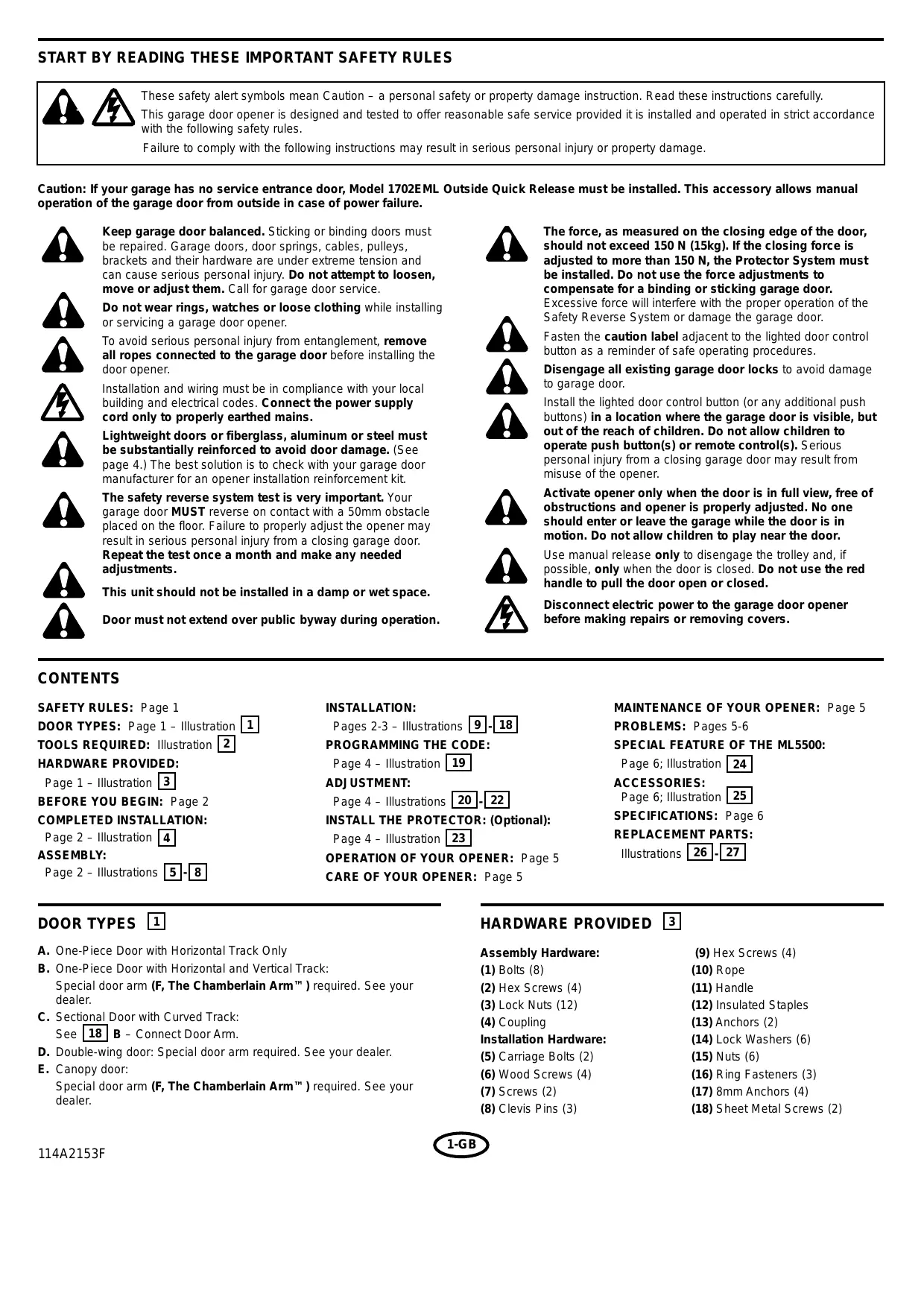
These safety alert symbols mean Caution - a personal safety or property damage instruction. Read these instructions carefully.
This garage door opener is designed and tested to offer reasonable safe service provided it is installed and operated in strict accordance with the following safety rules.
Failure to comply with the following instructions may result in serious personal injury or property damage.
Caution: If your garage has no service entrance door, Model 1702EML Outside Quick Release must be installed. This accessory allows manual operation of the garage door from outside in case of power failure.

Keep garage door balanced. Sticking or binding doors must be repaired. Garage doors, door springs, cables, pulleys, brackets and their hardware are under extreme tension and can cause serious personal injury. Do not attempt to loosen, move or adjust them. Call for garage door service.
Do not wear rings, watches or loose clothing while installing or servicing a garage door opener.
To avoid serious personal injury from entanglement, remove all ropes connected to the garage door before installing the door opener.


Installation and wiring must be in compliance with your local building and electrical codes. Connect the power supply cord only to properly earthed mains.
Lightweight doors or fiberglass, aluminum or steel must be substantially reinforced to avoid door damage. (See page 4.) The best solution is to check with your garage door manufacturer for an opener installation reinforcement kit.
The safety reverse system test is very important. Your garage door MUST reverse on contact with a 50mm obstacle placed on the floor. Failure to properly adjust the opener may result in serious personal injury from a closing garage door.
Repeat the test once a month and make any needed adjustments.
This unit should not be installed in a damp or wet space.
Door must not extend over public byway during operation.

The force, as measured on the closing edge of the door, should not exceed 150 N (15kg). If the closing force is adjusted to more than 150 N, the Protector System must be installed. Do not use the force adjustments to compensate for a binding or sticking garage door.
Excessive force will interfere with the proper operation of the Safety Reverse System or damage the garage door.
Fasten the caution label adjacent to the lighted door control button as a reminder of safe operating procedures.
Disengage all existing garage door locks to avoid damage to garage door.
Install the lighted door control button (or any additional push buttons) in a location where the garage door is visible, but out of the reach of children. Do not allow children to operate push button(s) or remote control(s). Serious personal injury from a closing garage door may result from misuse of the opener.
Activate opener only when the door is in full view, free of obstructions and opener is properly adjusted. No one should enter or leave the garage while the door is in motion. Do not allow children to play near the door.
Use manual release only to disengage the trolley and, if possible, only when the door is closed. Do not use the red handle to pull the door open or closed.
Disconnect electric power to the garage door opener before making repairs or removing covers.
CONTENTS
SAFETY RULES: Page 1
DOOR TYPES: Page 1 - Illustration
TOOLS REQUIRED: Illustration 2
HARDWARE PROVIDED:
Page 1-Illustration 3
BEFORE YOU BEGIN: Page 2
COMPLETED INSTALLATION:
Page 2 - Illustration 4
ASSEMBLY:
Page 2- Illustrations 5-8
INSTALLATION:
Pages 2-3 - Illustrations 9-18
PROGRAMMING THE CODE:
Page 4 - Illustration 19
ADJUSTMENT:
Page 4 - Illustrations [20] - [22]
INSTALL THE PROTECTOR: (Optional):
Page 4 - Illustration 23
Page 6; Illustration 24
ACCESSIONS:
Page 6; Illustration 25
SPECIFICATIONS: Page 6
REPLACEMENT PARTS:
Illustrations 26-27
DOORTYPES 1
A. One-Piece Door with Horizontal Track Only
B. One-Piece Door with Horizontal and Vertical Track: Special door arm (F, The Chamberlain Arm™) required. See your dealer.
C. Sectional Door with Curved Track: See 18 B-Connect Door Arm.
D. Double-wing door: Special door arm required. See your dealer.
E. Canopy door: Special door arm (F, The Chamberlain Arm™) required. See your dealer.
HARDWARE PROVIDED 3
Assembly Hardware:
(1) Bolts (8)
(2) Hex Screws (4)
(3) Lock Nuts (12)
(4) Coupling
Installation Hardware:
(5) Carriage Bolts (2)
(6) Wood Screws (4)
(7) Screws (2)
(8) Clevis Pins (3)
(9) Hex Screws (4)
(10) Rope
(11) Handle
(12) Insulated Staples
(13)Anchors (2)
(14) Lock Washers (6)
(15) Nuts (6)
(16) Ring Fasteners (3)
(17) 8mm Anchors (4)
(18) Sheet Metal Screws (2)
BEFORE YOU BEGIN:
- Look at the wall or ceiling above the garage door. The door/ header bracket must be securely fastened to structural supports.
- Do you have a finished ceiling in your garage? If so, a support bracket and additional fastening hardware (not supplied) may be required.
- Depending on your door's construction, you might need a special door arm. See your dealer.
- Do you have an access door in addition to the garage door? If not, Model 1702EML Outside Quick Release Accessory is required.
COMPLETED INSTALLATION 4
As you proceed with the assembly, installation and adjustment procedures in this manual, you may find it helpful to refer back to this illustration of a completed installation.
(1) Rail Brackets
(7) Light Lens
(2) Trolley
(8) Manual Release Rope & Handle
(3) Rail
(9) Curved Door Arm
(4) Hanging Bracket
(10) Straight Door Arm
(5) Power Cord
(11) Door/Header Brackets
(6) Opener
(12) Trolley Release Arm
ASSEMBLY SECTION 5.18
ASSEMBLE THE RAIL 5
- (Illustration 5A) Turn the opened rail carton upside down, emptying its contents onto a level work surface.
- Unfold the rails, taking care to avoid kinking the screw rod joints.
- (Illustration 5B) Rotate the rail sections so that the flat side is down and the screw side is up for all three lengths. Keep it clean and free of debris while you are working.
CAUTION: During assembly, avoid pulling the rail section housing the trolley rack (1) away from the screw rod. The rack is factory set about 230mm (9") from the end of the screw rod to the center of the rack.
If the plastic liner slides part way out during assembly, simply push it back in.
- (Illustration 5C) Beginning with the sprocket end (2), straighten the two rail sections so that the screw rod is in a straight line at the joint. (Avoid handling the joints, which may have sharp edges.)
- Carefully slide the pins (3) at the top edge of the rail into the openings (4) on the adjacent rail. It is essential that the rail assembly be on a level surface to achieve proper alignment and to avoid damage to the pins.
- Insert two bolts (5) through the center holes of a brace (6), and place its open length against the rail at this joint, aligning the holes as shown. Position another brace on the opposite side of the rail over the bolts, add lock nuts (7), and hand tighten. Insert two additional bolts and hand tighten.
- Keeping the rail straight and on a level surface, grasp the screw rods on each side of the remaining joint and pivot into a straight line. Repeat steps 5 and 6.
- With an 11mm wrench, tighten bolts til snug. Work from the center holes to those further from the joints. Do not overtighten.
FASTEN THE RAIL TO THE OPENER 6
Align the rail assembly (1) with the opener (2). Slip the coupling (3) over the rail sprocket (4). Slide the rail through the opener bracket (5) until the coupling fits securely over the opener sprocket (6). Align the two screw holes in the rail with those in the opener bracket. Insert two hex screws (7) and lock nuts (8). Tighten securely.
Slide the trolley (1) onto and along the bottom of the rail until it snaps firmly in place. Be certain to install it facing correctly: the trolley release arm must be horizontal (lock position), with its arrow pointed away from the opener.
ATTACH THE RAIL BRACKETS 8
Align rail brackets (1) with end of rail assembly. Insert two hex screws (2) and lock nuts (3). Tighten securely.
ASSEMBLY OF YOUR OPENER IS NOW COMPLETE.
INSTALLATION SECTION 9-18
Wear protective goggles when working overhead to protect your eyes from injury.
Disengage all existing garage door locks to avoid damage to the garage door.
To avoid serious personal injury from entanglement, remove all ropes connected to the garage door before installing the opener.
Installation of this product shall comply with ZH1/494, VDE 0700 Part 238, and VDE 0700 Part 1.
It is recommended that the opener be installed 2,1m (7 feet) or more above the floor where space permits.
The header bracket must be rigidly fastened to a structural support of the garage. Reinforce the wall or ceiling with a 40mm (1-1/2") board if necessary. Failure to comply may result in improper operation of safety reverse system.
You can attach the header bracket either to the header wall (1) or to the ceiling (3). Follow the instructions which will work best for your particular requirements.
With the door closed, mark the vertical centerline (2) of the garage door. Extend line onto header wall above the door.
Open door to highest point of travel. Draw an intersecting horizontal line on header wall 75mm (3") above high point to provide travel clearance for top edge of door.
A. Wall Mount: Center the bracket (2) on the vertical guideline (1) with the bottom edge of the bracket on the horizontal line (6) (with the arrow pointing toward the ceiling).
Mark either set of bracket holes (4 or 5). Do not use the holes designated for ceiling mount. Drill 4,5mm (3/16") pilot holes and fasten the bracket with wood screws (3).
B. Ceiling Mount: Extend vertical guideline (1) onto the ceiling. Center the bracket (2) on the vertical mark no more than 150mm (6") from the wall. Make sure the arrow is pointing toward the wall.
Mark holes designated for ceiling mount only (4). Drill 4,5mm (3/16") pilot holes and fasten the bracket with wood screws (3). For concrete ceiling mount, use concrete anchors (7) provided.
Position opener on garage floor below the header bracket. Use packing material to protect the cover.
Note: To enable the rail to clear sectional door springs, it may be necessary to lift opener onto a temporary support.
The opener must either be secured to a support or held firmly in place by another person.
Raise rail until rail brackets and header bracket come together. Join with clevis pin (1). Insert ring fastener (2) to secure.
POSITION THE OPENER 12
Note: A 25mm (1") board (1) is convenient for setting an ideal door-to-rail distance (unless headroom is not sufficient).
Raise the opener onto a stepladder. Open garage door. Place a 25mm (1") board (1) laid flat on the top section of door near the centerline as shown. Rest the rail on the board.
If the raised door hits the trolley, pull down on the trolley release arm to disconnect the inner and outer trolley sections. The trolley can remain disconnected until connecting door arm to trolley is completed.
HANG THE OPENER 13
The opener must be securely fastened to a structural support of the garage. Attach the hanging brackets toward the front of the opener as shown (1).
Three representative installations are shown. Yours may be different. Hanging brackets (2) should be angled (Figure A) to provide rigid support. On finished ceilings, (Figure B) attach a sturdy metal bracket (not supplied) (5) to a structural support before installing the opener. For concrete ceiling mount, (Figure C), use concrete anchors (6) provided. On each side of opener measure the distance from the opener to the structural support (or ceiling).
Cut both pieces of the hanging bracket to required lengths. Flatten one end of each bracket and bend or twist to fit the fastening angles. Do not bend at the bracket holes. Drill 4,5mm (3/16") pilot holes in the structural supports (or ceiling). Attach flattened ends of brackets to supports with wood screws (3).
Lift opener and fasten to hanging brackets with screw, lock washer and nut (4). Check to make sure rail is centered over the door. REMOVE 25mm (1") board. Operate door manually. If door hits the rail, raise header bracket.
ATTACH MANUAL RELEASE ROPE & HANDLE 14
Thread one end of rope (1) through hole in top of red handle so "NOTICE" reads right side up as shown (3). Secure with an overhand knot (2). Knot should be at least 25mm (1") from end of the rope to prevent slipping.
Thread other end of rope through hole in release arm of the outer trolley (4). Adjust rope length so that handle is 1,8m (6 feet) above the floor. Secure with an overhand knot.
Note: If it is necessary to cut rope, heat seal cut end with a match or lighter to prevent fraying.
CONNECT ELECTRIC POWER
To avoid installation difficulties, do not run the garage door opener until instructed to do so.
Connect the opener to a mains which is properly EARTHED (and as specified by local code).
Connect the door opener only to an outlet controlled by a double pole switch.
Locate push buttons where the garage door is visible, away from door and door hardware and out of the reach of children.
Serious personal injury from a moving garage door may result from misuse of opener. Do not allow children to operate the lighted door control button or remote control transmitter.
Fasten the caution label on the wall near the lighted door control button as a reminder of safe operating procedures.
There are 2 screw terminals (1) on the back of the lighted door control button (2). Strip about 6mm (1/4^) of insulation from bell wire (4). Separate wires enough to connect the white/red wire to terminal screw 1 and the white wire to terminal screw 2.
Fasten the lighted door control button to an inside garage wall with sheet metal screws (3) provided. Drill 4mm (5 / 32^ ) holes and use anchors (6) if installing into drywall or concrete. A convenient place is beside the service door and out of reach of children.
Run the bell wire up the wall and across the ceiling to the garage door opener. Use insulated staples (5) to secure wire. The receiver terminal screws (7) are located on the back panel of the opener. Connect the bell wire to the terminal screws as follows: white/red to 1 and white to 2.
Press to open or close the door. Press again to reverse the door during the closing cycle or to stop the door during opening cycle.
INSTALL THE LIGHTS AND LENS 16
Install a 40 watt maximum light bulb (1) in the socket as shown. The light will turn on and remain lit for 4-1/2 minutes when power is connected. After 4-1/2 minutes it will turn off.
Replace burned out bulbs with rough service light bulbs.
Apply slight pressure on sides of the lens (2) and slide tabs (3) into slots (4) in the end panel. Reverse the procedure to remove the lens.
FASTEN DOOR BRACKET 17
If yours is a canopy or dual-track style garage door, a door arm conversion kit is required. Follow the installation instructions included with the replacement door arm. Exercise care in removing and assembling arm conversion kit. Keep fingers away from the sliding parts.
NOTE: Horizontal and vertical reinforcement is needed for lightweight garage doors.
Sectional and One-Piece Door Installation Procedure:
- Center bracket (1) at the top of inside face of door as shown. Mark holes.
- A. Wooden doors
Drill 8mm (5/16") holes and fasten the door bracket with nut, lock washer, and carriage bolt (2).
B. Sheet metal doors
Fasten with sheet metal screws (3).
C. One-piece door optional
Fasten with sheet metal screws (3).
CONNECT DOOR ARM TO TROLLEY 18
Sectional Door Installation: Note door arm configuration in Figure B. One-Piece Door Installation: Procedure (Figure A).
Connect straight door arm (1) and curved door arm sections (2) to obtain the longest possible length with hardware (3, 4 & 5). With door closed, connect straight door arm section to door bracket with a clevis pin (6). Secure with a ring fastener (7).
Before connecting door arm to trolley, adjust travel limits. Limit adjustment screws are located on side panel.
Open Door Adjustment: Decrease up limit. Turn up limit adjustment screw counterclockwise 5-1/2 turns.
Press door control button. Trolley will travel to full open position (8). Manually raise door to open position (parallel to floor) and lift door arm (9) to trolley. The arm should touch trolley just in back of door arm connector hole (10) as shown in solid line drawing. Increase up limit if necessary. One full turn equals 5cm (2^) of door travel.
Closed Door Adjustment: Decrease down limit. Turn down limit adjustment screw clockwise 5 complete turns.
Press door control button. Trolley will travel to full closed position (11). Manually close door and lift door arm (12) to trolley. The arm should touch trolley just ahead of door arm connector hole (13) as shown in dotted line drawing. Decrease down limit if necessary. One full turn equals 5cm (2") of door travel.
Connect Door Arm to Trolley: With door closed, connect curved arm to trolley with remaining clevis pin. Secure with ring fastener. Note: Lift door slightly to make connection if necessary.
Run opener through a complete travel cycle. If door has a slight "backward" slant in full open position, decrease up limits until door is parallel to floor.
PROGRAM YOUR OPENER & REMOTE 19
Activate the opener only when door is in full view, free of obstruction and properly adjusted. No one should enter or leave garage while door is in motion. Do not allow children to operate push button(s) or remote(s). Do not allow children to play near the door.
Your garage door opener receives and remote control transmitter are set to a matching code. If you purchase additional remote controls, the garage door opener must be programmed to accept the new remote code.
Program the Receiver to Match Additional Remote Control Codes
- Press and hold the remote control push button (1).
- Press and release the "Smart" button (2) on the back panel of the opener. The opener light will flash once.
- Release the remote push button.
Now the opener will operate when the remote control push button is pressed.
If you release the remote control push button before the opener lights flash, the opener will not accept the code.
To Erase all Remote Control Codes
- Press and hold the "Smart" button on the opener panel until the indicator light turns off (about 6 seconds). All the codes the opener has learned will be erased.
- To reprogram, repeat Steps 1 - 3 for each remote control in use.
ADJUSTMENT SECTION 20-22
LIMITADJUSTMENT 20
Run the opener through a complete travel cycle. Limit adjustments are not necessary when the door opens and closes completely and doesn't reverse unintentionally in the fully closed position.
Situations requiring limit adjustment are listed below. Run the opener through a complete travel cycle after each adjustment.
NOTE: Repeated operation of the opener during adjustment procedures may cause motor to overheat and shut off. Allow a 15 minute cooling period after 5 continuous operations of the opener.
Read the following carefully before proceeding to Force Adjustment. Use a screwdriver to make limit adjustments.
If Door Doesn't Open Completely but Opens at Least 1,5m (5 feet): Increase up travel. Turn the up limit adjustment screw (1) clockwise. One turn equals 5cm (2") of travel.
If door does not open at least 1,5m (5 feet): Adjust up (open) force. See Force Adjustment.
If Door Doesn't Close Completely: Increase down travel. Turn down limit adjustment screw (2) counterclockwise. One turn equals 5cm (2") of travel. If the door still will not close completely, lengthen the door arm. If it still will not close completely, lower the header bracket.
If Opener Reverses in Fully Closed Position: Decrease down travel. Turn down limit adjustment screw (2) clockwise. One turn equals 5cm (2") of travel.
If Door Reverses when Closing and there is no Interference to Travel Cycle: Test door for binding. Pull manual release handle. Manually open and close door. If door is binding, call a door serviceman. If door is not binding or unbalanced, adjust down (close) force.
FORCE ADJUSTMENT 21
The force, as measured on the closing edge of the door, should not exceed 150 N (15kg). If the closing force is adjusted to more than 150 N, the Protector System must be installed.
Do not use force adjustments to compensate for a binding or sticking garage door. Excessive force will interfere with proper operation of safety reverse system or damage garage door.
Force Adjustment Controls (1 & 2) are located on the back panel of the opener.
If the force adjustments are set too light, door travel may be interrupted by nuisance reversals in down direction and stops in up direction. Weather conditions can affect the door movement, occasional adjustment may be needed.
Maximum force adjustment range is 260 degrees, about 3/4 of a complete turn. Do not force controls beyond that point. Turn force adjustment controls with a screwdriver.
Test Down (Close) Force: Grasp the door handle or door bottom when door is about halfway through down (close) travel. Door should reverse. Reversal halfway through down travel does not guarantee reversal on a 50mm obstruction. If the door is hard to hold or doesn't reverse, decrease down (close) force by turning the control (2) in a counterclockwise direction. Make small adjustments until door reverses normally. After each adjustment, run opener through a complete cycle.
If Door Doesn't Open at Least 1,5m (5 feet): Increase up (open) force by turning the control (1) in a clockwise direction. Make small adjustments until door opens completely. Re-adjust up limit if necessary. After each adjustment, run opener through a complete travel cycle.
If Door Reverses During Down (Close) Cycle: Increase down (close) force by turning the control (2) in a clockwise direction. Make small adjustments until door completes close cycle. After each adjustment, run the opener through a complete travel cycle. Do not increase the force beyond the minimum amount required to close the door.
TEST THE SAFETY REVERSE SYSTEM 22
The safety reverse system test is important. Garage door must reverse on contact with a 50mm obstacle laid flat on the floor. Failure to properly adjust opener may result in serious personal injury from a closing garage door. Repeat test once a month and adjust as needed.
Procedure: Always begin with door in fully open position. Place a 50mm obstacle (1) laid flat on the floor under the garage door. Operate the door in the down direction. The door must reverse on the obstruction. If the door stops on the obstruction, it is not traveling far enough in the down direction. Increase the down limit by turning down limit adjustment screw counterclockwise 1/4 turn. Repeat test.
When the door reverses on the 50mm obstacle, remove the obstruction and run the opener through a complete travel cycle. Door must not reverse in closed position. If it does, adjust Limits and Force and repeat safety reverse test.
INSTALL THE PROTECTOR 23
(See accessories)
The force, as measured on the closing edge of the door, should not exceed 150N (15kg). If the closing force is adjusted to more than 150N , the Protector System must be installed.
After opener has been installed and adjusted, The Protector System™ accessory can be installed. Instructions are included with this accessory.
The Protector System™ provides an additional measure of safety against a small child being caught under a garage door.
It uses an invisible beam which, when broken by an obstruction, causes a closing door to open and prevents an open door from closing. It is strongly recommended for homeowners with young children.
Your opener can be activated by any of the following devices:
- The Lighted Door Control Button. Hold the button down until door starts to move.
- The Outside Keylock or Keyless Entry System (if you have installed either of these accessories).
- The Remote Control Transmitter. Hold the push button down until the door starts to move.
Opening the Door Manually:
Door should be fully closed if possible. Weak or broken springs could allow an open door to fall rapidly. Property damage or serious personal injury could result.
The door can be opened manually by pulling the release handle straight down (so that the trolley release arm snaps into a vertical position). To reconnect the door, pull the release handle toward the opener at a 45^ angle so that the trolley release arm is horizontal. See illustration 14.
Do not use the manual release handle to pull the door open or closed. When the Opener is Activated by Remote Control or Lighted Door Control Button:
- If open, the door will close. If closed, the door will open.
- If closing, the door will reverse.
- If opening, the door will stop (allowing space for entry and exit of pets and for fresh air).
- If the door has been stopped in a partially open position, it will close.
- If an obstruction is encountered while closing, the door will reverse.
- If an obstruction is encountered while opening, the door will stop.
- The optional Protector System™ uses an invisible beam which, when broken by an obstruction, causes a closing door to open and prevents an open door from closing. It is STRONGLY RECOMMENDED for homeowners with young children.
Allow a 15 minute cooling period after 5 continuous operations of the opener.
The opener light will turn on: 1. when opener is initially plugged in;
- when the power is interrupted; 3. when the opener is activated.
The light turns off automatically after 4-1/2 minutes. Bulb size is 40 Watts maximum.
CARE OF YOUR OPENER
When properly installed, opener will provide high performance with a minimum of maintenance. The opener does not require additional lubrication.
Limit and Force Adjustments: These adjustments must be checked and properly set when opener is installed. Only a screwdriver is required. Weather conditions may cause some minor changes in the door operation, requiring some re-adjustments, particularly during the first year of operation.
Refer to the limit and force adjustments on page 4. Follow the instructions carefully and repeat the safety reverse test after any adjustment.
Remote Control Transmitter: The portable remote control may be secured to a car sun visor with the clip provided. Additional remotes can be purchased at any time for use in all vehicles using garage. Refer to Accessories. The receiver must be programmed to operate with any new remote.
Remote Control Battery: The lithium batteries should produce power for up to 5 years. When the light becomes dim or does not come on, replace the battery. If transmission range lessens, check the battery test light.
To Change Battery: To replace batteries, use the visor clip or screwdriver blade to pry open the case. Insert batteries positive side up. To replace cover, snap shut along both sides. Do not dispose of the old battery with household waste. Take batteries to a proper disposal center.
MAINTENANCE OF YOUR OPENER
Once a Month:
- Repeat safety reverse test. Make any necessary adjustments.
- Manually operate door. If it is unbalanced or binding, call for professional garage door service.
- Check to be sure door opens and closes fully. Adjust Limits and/or Force if necessary.
Once a Year:
Oil door rollers, bearings and hinges. The opener does not require additional lubrication. Do not grease the door tracks.
HAVING A PROBLEM?
1. Opener doesn't operate from either door control or remote:
- Does the opener have electric power? Plug lamp into outlet. If it doesn't light, check the fuse box or the circuit breaker. (Some outlets are controlled by a wall switch.)
- Have you disengaged all door locks? Review installation instruction warnings on page 1.
- Is there a build-up of ice or snow under door? The door may be frozen to ground. Remove any obstruction.
- The garage door spring may be broken. Have it replaced.
- Repeated operation may have tripped the overload protector in the motor. Wait 15 minutes. Try again.
2. Opener operates from remote but not from door control:
- Is door control button lit? If not, remove the bell wire from the opener terminals. Short the red and white terminals by touching both terminals at the same time with a piece of wire. If the opener runs, check for a faulty wire connection at the door control, a short under the staples, or a broken wire.
- Are wiring connections correct? Review page 3.
3. Door operates from door control but not from remote:
- Check the battery test light. Replace battery if necessary.
- If you have two or more remotes and only one operates, review receiver programming procedures on page 4.
- Is the door control button flashing? The opener receiver must re-learn the remote control code. Follow the instructions on page 4.
4. Remote has short range:
- Is battery installed? Check battery test light. If the light is dim, change the battery.
- Change the location of the remote control on the car.
- A metal garage door, foil-backed insulation or metal siding will reduce the transmission range.
- Make sure antenna is fully extended across ceiling towards the door.
5. Door reverses for no apparent reason and opener lights don't blink:
- Is something obstructing the door? Pull manual release handle. Operate door manually. If it is unbalanced or binding, call for professional garage door service.
- Clear any ice or snow from garage floor area where garage door closes.
- Review Force Adjustment.
- If door reverses in FULLLY CLOSED position, decrease travel limits.
Repeat safety reverse test after adjustment is complete.
The need for occasional adjustment of the force and limit settings is normal. Weather conditions in particular can affect door travel.
6. Door reverses for no apparent reason and opener lights blink for 5 seconds after reversing:
Check The Protector System™ (if you have installed this accessory). If the light is blinking, correct alignment.
HAVING A PROBLEM? (Continued)
7. Opener noise is disturbing in living quarters of home:
If operational noise is a problem because of proximity of the opener to the living quarters, Vibration Isolator Kit 41A3263 can be installed. This kit was designed to eliminate the "sounding board effect" and is easy to install.
8. The garage door opens and closes by itself:
- Is there a neighbor with a garage door opener using the same frequency code? Change your code.
- Make sure remote push button is not stuck "on."
9. Door stops but doesn't close completely:
Review Travel Limits Adjustment.
Repeat safety reverse test after any adjustment of door arm length, close force or down limit.
10. Door opens but won't close:
- Check The Protector System™ (if you have installed this accessory). If the light is blinking, correct alignment.
- If opener lights do not blink and it is a new installation, check the down force.
Repeat the safety reverse test after the adjustment is complete.
11. Opener light does not turn on:
Replace light bulb (40 Watts maximum). Replace burned out bulbs with rough service light bulbs.
12. Opener light does not turn off:
There may be a defective earth at the ceiling or wall receptacle. The unit must be earthed.
13. Opener strains or maximum force is needed to activate door:
Door may be unbalanced or springs are broken. Close door and use manual release rope and handle to disconnect trolley. Open and close door manually. A properly balanced door will stay in any point of travel while being supported entirely by its springs. If it does not, call for professional garage door service to correct the problem. Do not increase the force to operate the opener.
14. Opener motor hums briefly, then won't work:
- Garage door springs are broken. SEE ABOVE.
- If problem occurs on first operation of opener, door may be locked. Disable door lock.
15. Opener won't activate due to power failure:
- Pull manual release rope and handle straight down to disconnect trolley. Door can be opened and closed manually. When the power is restored, pull the manual release handle toward the opener at a 45^ angle, so that the trolley release arm is horizontal. The next time the opener is activated, the trolley will reconnect.
- The Outside Quick Release accessory 1702EML (if fitted) disconnects the trolley from outside the garage in case of power failure.
Door within a door connection
Remove cover. Locate auxiliary terminal block. Remove jumper from terminal leads 1 and 2 (not shown). Replace with magnetic contact switch leads as shown.
ACCESSORIES 25
(1) Model 4330EML Single-Function Remote Control
(2) Model 4333EML 3-Function Remote Control
(3) Model 4335EML 3-Function Mini Remote Control
(4) Model 845EML Multi-Function Door Control Panel
(5) Model 75EML Lighted Door Control Button
(6) Model 747EML Wireless Keyless Entry Keypad
(7) Model 760EML Outside Keylock
(8) Model 1702EML Outside Quick Release
(9) Model 770EML The Protector SystemTM
(10) Model 1EML Door Handle Quick Release
(11) Model 34EML 2-Position Key Switch Flush Mount
Model 41EML 2-Position Key Switch Surface Mount
(12) Model 1703EML The Chamberlain ArmTM
WIRING INSTRUCTIONS FOR ACCESSORIES
Lighted Push Button:
To opener terminals:
Red-1 and White-2
Outside Keylock:
To opener terminals:
Red-1 and White-2
Protector SystemTM:
To opener terminals:
White-2 and Black-3
Wall Control Panel:
To opener terminals:
Red-1 and White-2
REPLACEMENT PARTS 26-27
SPECIFICATIONS
Max.Pull Force. 900N
Watts 600
Motor
Type...Permanent split capacitor
Speed 1500 rpm
Volts. 230-240 Volts AC-50Hz Only
Drive Mechanism
Reduction. 1.27:1
Drive. Screw. 2 Lead worm. Aluminum rail.
Length of Travel .......Adjustable to 2,23m (7.4 feet)
Travel Rate............152mm (6 inches) per second
Lamp . . . . . . . . . . . . . . . . . . . . . . . . . . . . . . . . . . . . . . . . . . . . . . . . . . . . . . . . . . . . . . . . . . . . . . . . . . . . . . . . . . . . . . . . . . . . .. On when door starts, off 4-1/2 minutes after stop.
Door Linkage............Adjustable door arm. Pull cord trolley release.
Safety
Personal ...Push button and automatic reversal in down direction. Push button and automatic stop in up direction.
Electronic............Independent up and down force adjustment screws.
Electrical............Motor overload protector and low voltage push button wiring.
Limit Adjustment......Screwdriver adjustment on side panel.
Start Circuit .... Low voltage push button circuit.
Dimensions
Length (Overall) 3,1m (122 inches)
Headroom Required....6cm (2.3 inches)
Hanging Weight. 19 kg (41.8 lb)
Receiver Memory Registers
Computer Code. 12
Code Switch. 1
Keypad 1

Side 1 - illustration 3
FOR DU BEGYNDER: Side 2
FAERDIG INSTALLATION:
Side 2 - illustration
SAMLING:
Side 2 - illustration 5-8
MONTAGE:
Side 2-4 - illustration 9-18
PROGRAMMERING AF KODE:
Side 4 - illustration 19
JUSTERUNG:
Side 4 - illustration [20] - [22]
INSTALLATION AF FOTOCELLE:
(ekstraudstyr): Side 5 - illustration [23]
BETJENING AF ABNEREN: Side 5
PLEJE AF ABNEREN: Side 5
VEDLIGEHOLDELSEFABNEREN:Side 5
PROBLEMER: Side 6
SPECIELLE FUNKTION PÁ ML5500:
Side 6 - illustration 24
EKSTRAUDSTYR:
Side 7 - illustration 25
SPECIFICATIONER: Side 7
RESERVEDELE:
illustration 26-27
PORTTYPER 1
A. Vippeport med vandret koreskinne
B. Vippeport med lodret og vandret koreskinne:
INSTALLATIONSAFSNIT 9.18
Manager, Reg. Affairs

Manager, Reg. Affairs

Ta ouoBoa nou 6eTne unObnawovn Poooxn - onyia oxetikn e aopaleia n npoiouiaekn o0pa. Aiaabaote autou tou iouc Tic onnyie c ne pooxh.
O napwunxaviooc ykapazonoptac exi oxdeltaei kai dokiaotei wote va npoeppeia aopaa h aeitoupyia oe loyika nlaiaiae TnV npounoean otE xei totothei kai xpnoiponoitei aoutnp oupwvia e toucapakawovc aopaaieiac.
Mn oumuoppwn e Tt npakatw odnyec mnpoei va exoav anotelao oobapno pooaniktopaunio npiouiaek bopa.
IPOSOXH: Av to ykapac oac dev exi 60nntik npoia va xnoiponoi ng i Eeepikoc Mxavioa Taeia Aneaupewans, movteo un' apiouv 1702EML. To eaptnua auto emptenei tny ano eew xipokivtn aeitoupyia ntc ykapaconoprtac oe pintwn diakomnc peuato.

Aiatnpie Tny ykapaonopta 100cuyioevn. Ipotec nou kOlambdae
muika n TEAEiWC npetv a eniioipwovtai. KapaZoTOpTeC,
EAtmPia, oumuatooxiva, tpoxAiec, unooTpiyata kal o
EOnAIOuO tsou cbiokovtai oe kataoan ELaepetikn CpoeVtaanC
kai npopouv va npokaeeouv oBapTo pauatuao. Mny
EmieipoiTe VA kaapowete, va metakivnoe ne va ta puhoioeTe.
Kaote evav texvikoiya kapaonoptc yi service.
Mn φopáte δaxtuδia, poλóγia n xaIapó pouxioó òav εykaθIoTATE η αυνηρεITE tyn ykapaçɔntopta.
Tia nTv antopuyn oobapou npoownikou tpaumatou ano
Tepinokn/mep6ea, apapeote 0a ta oxovia nou eivai npooedmuoc.
Otvnykapaonopra niv EYkataotnoetev TOnxavioq aoiyuatoC.
H eykataotaan nC ykapaconopactc kai n NkEtpkn Eykataoaon
npenv v eivai oupwvne Touc tonikooc iokodukoc kai
NkEtploavykouc kwokcs, SuVbEOT KAALWDIO npoxnc
puatoc mvo stowta iWmevo pumatobotn.
Elaepes ykapoontec kataeuaevc ano ualobabaka (fiberglass), aouuivio n xAua6a npenei va evxuovnmuavtia yia va anoeuxei thaoitous. (BaeTe oelid 5.) H kalutepn luon eiva va ououleute tnv kataoekauotpi eta taipieia yia to KIT eviaxuoc ykataoatac mXyaviou ovoiyatoc.
SYNTHPHESH TOY MHXANIEMOY
ANOIRMATOZ: i a6
EΓΚΑΤΑΣΤΗΣTE THN BΛΣH KEΦΑΛΗΣ 10
A. Ekyktaoan o ToiXo: KevtpapetE Tn BaoN (2) Otnv kataKOpupn ypaun-0bnyo (1) ME TO KAtpw akpo TnC BaoNc Otnv opIoVOTia Ypaun, onwc paiveta OTO Oxma (6) (ME TO BéLoC va δeixvI npoc Tnv opoP).
MapkapeTc onoia ano tic oneC tnc baonc (4 & 5).MnV xnpouonoiOneTc oneC nou npooipocovai yekataaotaon otyn oopn. AvoTe trpune, diapetpu 4,5 mm kal epeewote to otpiyma EuIobic3.
B. Ekyataoan o opn: Pnoekteivte nV katakopun ypaumnoy (1) Otv npoqn. Kevtpapet Tn bao (2) 0To katako-puO oneio xipoootepo ano 150mm ano tov tox. tyouputei to To dixvpioc tov tox.
MapkapeTc moV Tc otc nou npoipocvta yia EykaTaotaon oToV Toixo (4). AvoTE trpuec diaeTpou 4,5 mm kai otpeewote to otpiya eLuolobec (3).Ia avaptnon oE tauevtevia opofn, xnoaemonoiote Tc napexoevec aykupowcic (7).
SYNTHPHESH TOY MHXANEMOY ANOIIMATO
Mnviaia Suvtnpno:
- Enavaalabet n dookun tou ouotmuatc aoepaiaacavioptpocn. Kavte n antapaitntc puthetaic.
Xpnaiouoioane TnV npota xepokivnta. Av dEv ivai 1ooCuyioeyn n kOlambdaia KaEOTe KAnIOIov EIdiko.
Eλεγξεν av η πόρτa avoiyει και κλείνει τελείως. Pθμισε, av xρειαζεται, το ὄριδιαβρούης και/η τις δυνάμεις.
Etioia Suvtnpn:
Ainavte Touc kuivopouc kuiom, ta poueav kai touc eveoedc. O
mXaviooc avoiuatoC dev xpeiaetai kamuia npooetn Ainavon. Mn
Ainavte Touc oBnpodpoouc mnpotac.
AlpwouEvo Bapoc 19 kg
KataxwpntecMvnncAektn
Kwokoc unoloyotn 12
Manager, Reg. Affairs

delles Normative EU 1999/5/EC, 73/23/EEC, 89/336/EEC
Manager, Reg. Affairs

VEDLIKEHOLD AV APNEREN: Side 5
PROBLEM: Side 5-6
SPESIALFUNKSJONER PÁ ML5500:
VEDLIKEHOLD AV ÅPNEREN
Vedlikehold en gang i maneden:
- Gjenta testen av sikkerhetsreverseringen. Foreta nadvendige justeringer.
- Betjen porten manuelt. Hvis den er i ubalanse eller er treg, bør du kontakte et serviceverksted.
- Kontroller at porten Åpner og lukker seg fullstendig. Juster grensene og/eller kraften hvis det er nødvendig.
HAR DU PROBLEMER? (Continued)
Registre for mottakerminne
Datakode 12
Kodebryter 1
Knappepanel.1
Automatisk garasjeportapner . Modell ML5500
samsvarer med
Manager, Reg. Affairs

Manager, Reg. Affairs


Manager, Reg. Affairs


Denna varningssignal pakallar forsiktiget - anvisning betraffande personlig sakerhet eller egendomskada. Läs dessa anvisningar noggrant.
1999/5/EC, 73/23/EEC, 89/336/EEC
Manager, Reg. Affairs

Manager, Reg. Affairs

| CH | A | D | Abbildungen | - | Garagentoröffner Modell MotorLift 5500 | | |
| CH | B | F | Figures | - | Modèle MotorLift 5500 de ouvre-porte de garage | | |
| | | GB | Illustrations | - | Garage Door Operator Model MotorLift 5500 | |
| | | DK | Illustration | - | Model MotorLift 5500 Garageportsåbner | |
| | | E | Illustraciones | - | Abridor de la puerta de garage,
Modelo MotorLift 5500 | |
| | | GR | Σχήμα | - | Mηχανισμός Ανοίγματος Γκαραζόπορτας,
Movτέλο MotorLift 5500 | |
| | | I | Illustrazioni | - | Apriorta per garage Modello MotorLift 5500 | |
| | | N | Illustrasjon | - | Garasjeportåpner, Modell MotorLift 5500 | |
| | | B | NL | Afbeeldingen | - | Model MotorLift 5500 Garagedeuropeaner |
| | | P | Figuras | - | Operador automatico de porta,
Modelo MotorLift 5500 | |
| | | S | Bild. | - | Garageportöppnare Modell MotorLift 5500 | |
| | | SF | Kuvat | - | Autotallin ovenavaaja, Malli MotorLift 5500 | |


2

3

4


5


6


13


14

15


16

17


18

19

20
21


22

23


24

25
4330EML

4333EML

4335EML

845EML

75EML

747EML
1703EML


760EML

1702EML

770EML

1EML

34EML/41EML
11


10A20


25A18

41A4795
12B569-1 12B569-2


41C4677
675-1

217A238


41A2828

12B350

29C128

178B34

178B35