HC300MLS-ML2 - Garage door opener CHAMBERLAIN - Free user manual and instructions
Find the device manual for free HC300MLS-ML2 CHAMBERLAIN in PDF.
User questions about HC300MLS-ML2 CHAMBERLAIN
0 question about this device. Answer the ones you know or ask your own.
Ask a new question about this device
Download the instructions for your Garage door opener in PDF format for free! Find your manual HC300MLS-ML2 - CHAMBERLAIN and take your electronic device back in hand. On this page are published all the documents necessary for the use of your device. HC300MLS-ML2 by CHAMBERLAIN.
USER MANUAL HC300MLS-ML2 CHAMBERLAIN
AT/BA/BE/BG/CH/CY/CZ/DE/DK/ES/
FR/GB/GR/HR/HU/IE/IS/IT/LU/MT/NL/
NO/PL/PT/RO/RU/SE/SI/SK/TR/YU
Manager, Regulatory Affairs
Chamberlain GmbH
D-66793 Saarwellingen
Januar, 2006

Barbarea P. Keckhoft
INSTRUCTIONS IMPORTANTES POUR LE MONTAGE ET L'UTILISATION
VEUILLEZ TOUT D'ABORD LIRE CES REGLES DE SECURITE IMPORTANTES

Manager, Regulatory Affairs
Chamberlain GmbH
D-66793 Saarwellingen
Januar, 2006

Daibua P. Keckho
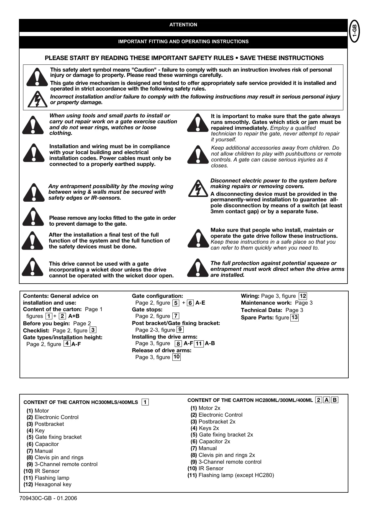
IMPORTANT FITTING AND OPERATING INSTRUCTIONS
PLEASE START BY READING THESE IMPORTANT SAFETY RULES • SAVE THESE INSTRUCTIONS

This safety alert symbol means "Caution" - failure to comply with such an instruction involves risk of personal injury or damage to property. Please read these warnings carefully.

This gate drive mechanism is designed and tested to offer appropriately safe service provided it is installed and operated in strict accordance with the following safety rules.
Incorrect installation and/or failure to comply with the following instructions may result in serious personal injury or property damage.

When using tools and small parts to install or carry out repair work on a gate exercise caution and do not wear rings, watches or loose clothing.

Installation and wiring must be in compliance with your local building and electrical installation codes. Power cables must only be connected to a properly earthed supply.

It is important to make sure that the gate always runs smoothly. Gates which stick or jam must be repaired immediately. Employ a qualified technician to repair the gate, never attempt to repair it yourself.

Keep additional accessories away from children. Do not allow children to play with pushbuttons or remote controls. A gate can cause serious injuries as it closes.

Any entrapment possibility by the moving wing between wing & walls must be secured with safety edges or IR-sensors.

Please remove any locks fitted to the gate in order to prevent damage to the gate.

After the installation a final test of the full function of the system and the full function of the safety devices must be done.

Disconnect electric power to the system before making repairs or removing covers.
A disconnecting device must be provided in the permanently-wired installation to guarantee all-pole disconnection by means of a switch (at least 3mm contact gap) or by a separate fuse.

Make sure that people who install, maintain or operate the gate drive follow these instructions. Keep these instructions in a safe place so that you can refer to them quickly when you need to.

This drive cannot be used with a gate incorporating a wicket door unless the drive cannot be operated with the wicket door open.

The full protection against potential squeeze or entrapment must work direct when the drive arms are installed.
Contents: General advice on installation and use:
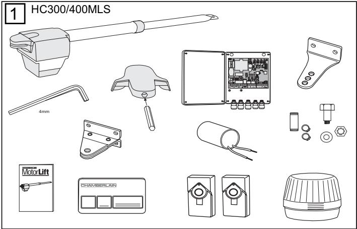
Content of the carton: Page 1
figures 1 + 2A + B
Before you begin: Page 2
Checklist: Page 2, figure 3
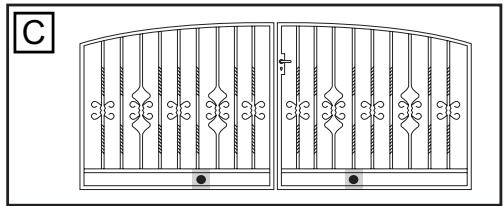
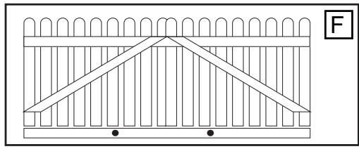
Gate types/installation height:
Page 2, figure 4A-F
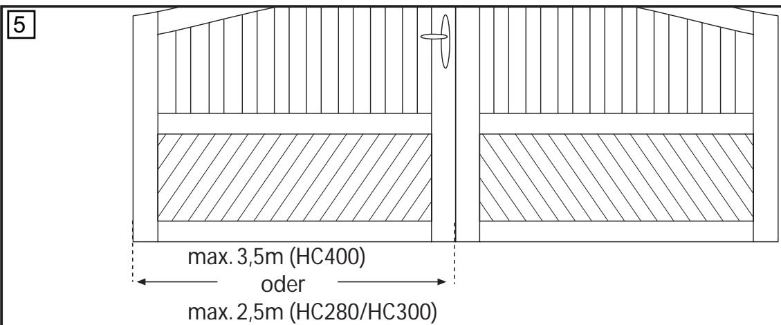
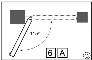
Gate configuration:
Page 2, figure 5 + 6 A-E
Gate stops:
Page 2, figure 7
Post bracket/Gate fixing bracket:
Page 2-3, figure 9
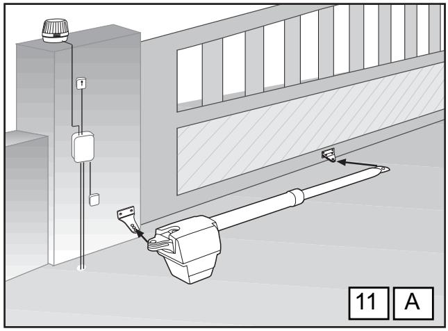
Installing the drive arms:
Page 3, figure A-F11A-B
Release of drive arms:
Page 3, figure 10
Wiring: Page 3, figure 12
Maintenance work: Page 3
Technical Data: Page 3
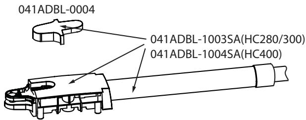
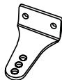
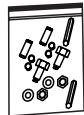
Spare Parts: figure 13
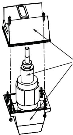
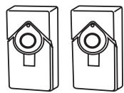
CONTENT OF THE CARTON HC300MLS/400MLS 1
(1) Motor
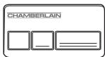
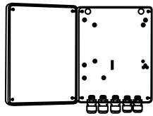
(2) Electronic Control
(3) Postbracket
(4) Key
(5) Gate fixing bracket
(6) Capacitor
(7) Manual
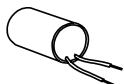
(8) Clevis pin and rings
(9) 3-Channel remote control
(10) IR Sensor
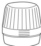
(11) Flashing lamp
(12) Hexagonal key
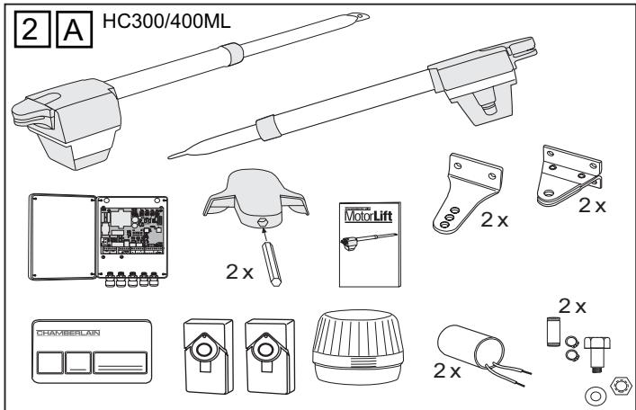
CONTENT OF THE CARTON HC280ML/300ML/400ML 2AB
(1) Motor 2x
(2) Electronic Control
(3) Postbracket 2x
(4) Keys 2x
(5) Gate fixing bracket 2x
(6) Capacitor 2x
(7) Manual
(8) Clevis pin and rings 2x
(9) 3-Channel remote control
(10) IR Sensor
(11) Flashing lamp (except HC280)
BEFORE YOU BEGIN
The drive mechanism needs room to the side permitting correct installation of drive arms. Please make sure that this is available. Gates affected by high wind loads must also be protected by an (electric) lock.
There are many factors to consider when choosing the right drive mechanism. Assuming that a gate functions properly, "startup" is the most difficult phase, once the gate is in motion, significantly less force is usually required to move it.
- Gate size: Gate size is a very important factor. Wind can brake or distort the gate, thereby increasing the amount of force needed to move it considerably.
- Gate weight: The weight of the gate in not as relevant as the size.
- Effect of temperature: Low outdoor temperatures can make initial startup more difficult (changes in the ground, etc.) or even prevent it. High outdoor temperatures along with frequent use can trigger thermal protection prematurely (approx. 135^ ).
- Operating frequency/operating time: Drive mechanisms are designed for a maximum operating time (running time) of approximately 30% (e.g. 30% during any one hour).
IMPORTANT: The drive mechanism is not designed to operate continuously at its maximum operating time (non-stop operation). Otherwise the drive mechanism becomes too hot and switches off until it cools down to the switch-on temperature. The outdoor temperature and the gate are important parameters that affect the actual operating time.
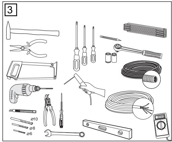
INSTALLATION CHECKLIST - PREPARATIONS
Check the carton contents and read the instructions carefully. Make sure your gate equipment operates perfectly. The gate must run evenly and smoothly and must not stick at any point. Remember that the ground level may be several centimeters higher in winter. The gate must be stable and as free of backlash in order to prevent any unwanted movement. The more smoothly the gate wing runs, the more sensitive the force adjustment must be.
Write down any materials you still need and obtain them before starting to install. Heavy-duty plugs, bolts, gate stops, cables, distribution boxes, tools, etc.
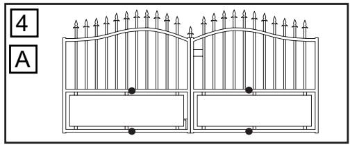
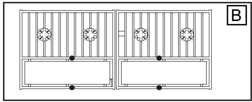
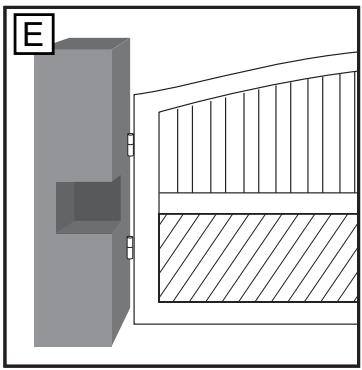
GATE TYPES
The gate type determines the location where the drive mechanism is installed. If the gate stop is on the ground, the drive mechanism must also be installed at a height that is as low as possible so that it cannot twist the gate. Use only parts of the gate frame for fixing purposes.
For steel gates, the gate fitting must be attached to the main frame. If you are uncertain whether the available support is sufficiently stable, reinforce it.
In the case of wooden gates, the gate fitting must be bolted through. It is advisable to fit a plate from the outside so that the fixing brackets cannot become loose over time. Thin wooden gates must also be reinforced in order to withstand the stresses encountered.
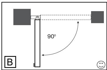
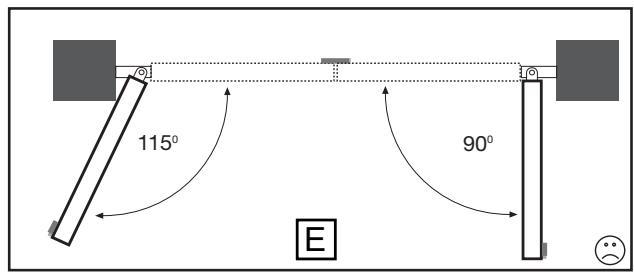
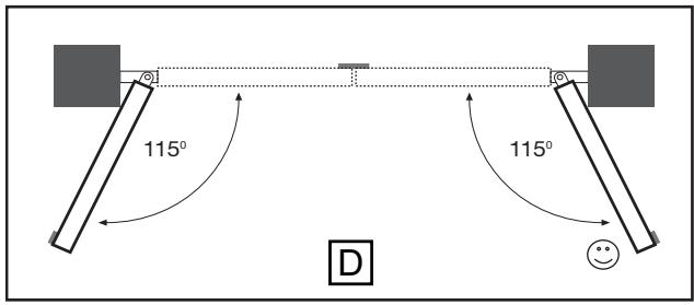
GATE CONFIGURATION
How far must the gate wing open?
90 degrees or up to 115 degrees. An opening angle in excess of 115 degrees is possible but is not recommended. Reason: the drive mechanism always runs at the same speed. The further the gate has to be opened, the faster the wing must travel. Movement becomes more erratic and this subjects the fittings and gate to extreme stresses. Different opening angles cause one motor to reach its destination first, but continues to run, thereby forcing the gate up against the gate stop until the other motor eventually reaches its end position.
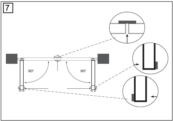
GATE STOPS
A SWING GATE NEEDS A FIXED GATE STOP IN BOTH THE OPEN AND CLOSE POSITIONS. Gate stops save wear and tear on the motor, gate and fittings. Operating a gate without fixed limit stops results in poor performance. It is often dangerous, leads to premature wear and voids your warranty!
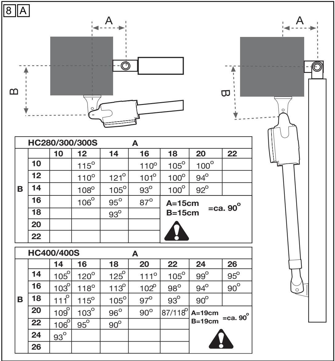
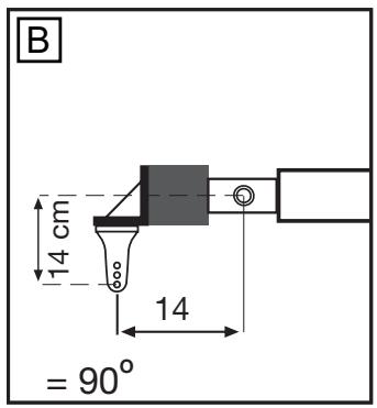
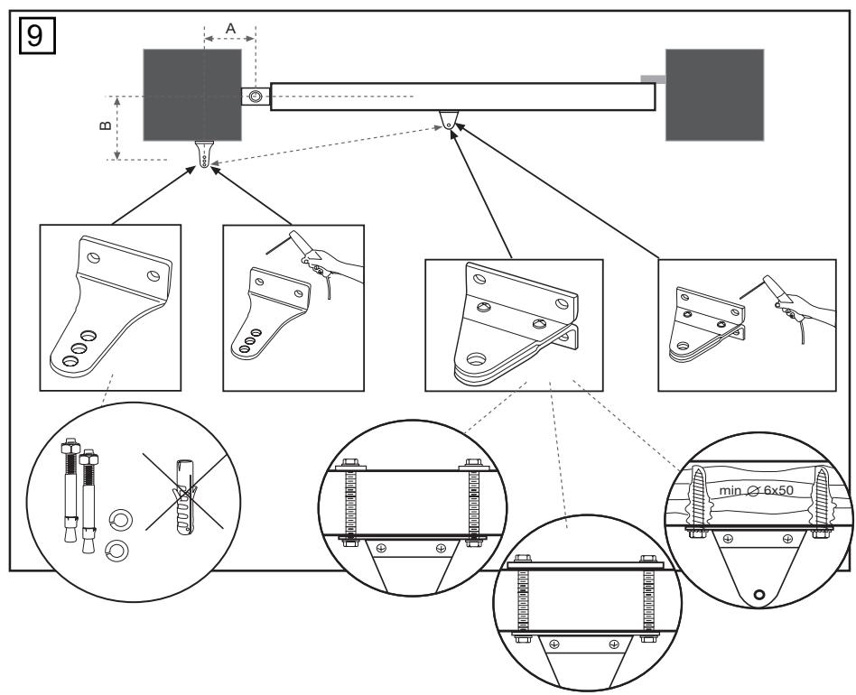
POST FIXING BRACKET
Choosing the correct location for the post fixing bracket has a decisive impact on the subsequent functioning of the system. It determines the distance between the motor's centre of motion and the gate's centre of motion and hence the opening angle. These dimensions are referred to as dimension A and dimension B. Do not underestimate the effect that these dimensions have on correct functioning and running. Try to achieve the best possible dimension for your opening angle that is suitable for all circumstances. See Table for dimensions A/B.
If the post is not wide enough, an extension piece must be fitted to it. If the post is too thick, cut out part of it to make it thinner or offset the gate.
To obtain ideal dimensions, it may be necessary to shorten or lengthen the supplied hinge plate. In the case of gates that are to be custom made, if the gate hinges are fitted on the posts appropriately, it is possible to influence dimensions A and B. Before the final mounting dimensions are determined, you should always check whether or not there is any possibility that the corner of the drive mechanism will hit the post as the gate swings.
INSTALLATION: The drive mechanism exerts considerable force against the post. Usually, acceptable mounting dimensions are obtained if the supplied hinge plate is welded directly onto the post. In the case of thick stone or concrete posts, the hinge must be welded to a base plate and attached so that the plugs cannot work loose during operation. Heavy-duty plugs where a threaded rod is bonded into the masonry stress-free are more suitable for this purpose than steel or plastic straddling plugs. In the case of brickwork pillars, bolt a relatively large steel plate that covers several bricks on to it and then weld the hinge plate to it. An angled plate attached over the corner of the post is also a good means of fixing the operators.
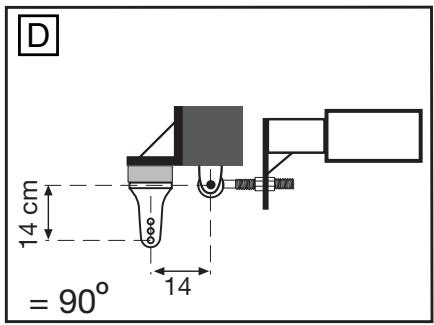
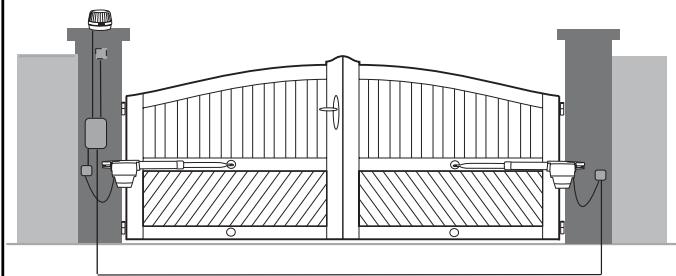
GATE FITTING
The gate fitting must be installed so that it is horizontal relative to the post bracket. The distance between the gate bracket and post bracket is referred to as the "arm span". When the gate is closed, the drive mechanism is 99% extended. When the gate is opened, the drive mechanism is 1% extended. Fully retracting or extending the plunger/spindle in operation (with gate) damages the drive mechanism and voids the warranty. It is absolutely imperative to comply with the required arm span under all circumstances!
For steel gates, fixings should be welded on or through bolted. When through bolting the gate, use large washers or a plate on the other side. The drive mechanism exerts an extremely high force on this joint.
Fixings must be through bolted for wooden gates. It is recommended that metal plates be fitted on either side of the gate, to prevent the fixings from becoming loose. (i.e. Type 2F)
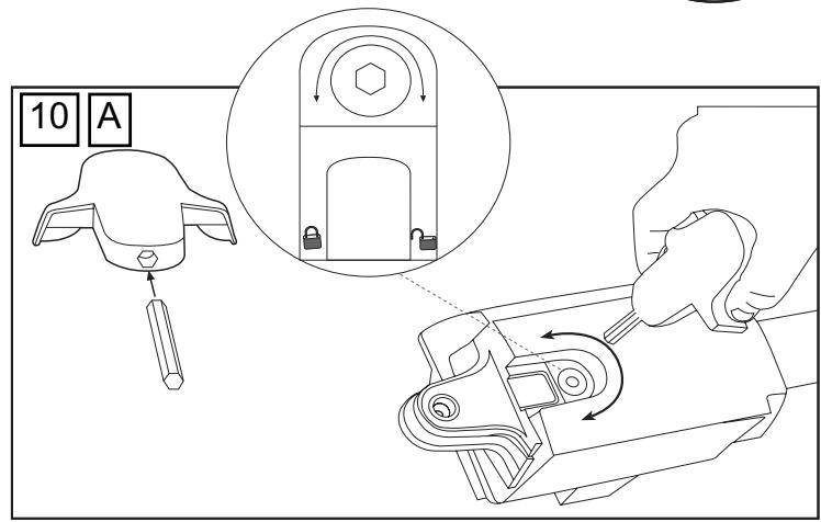
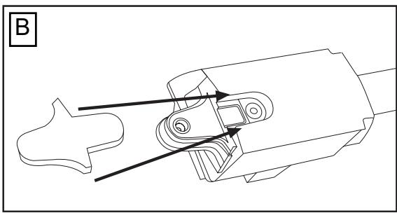
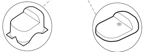
RELEASE
The drive mechanism can be released. The gate can then be opened and operated manually (power failure). With a new drive mechanism, the release action may sometimes feel stiff/jerky. This is normal and has no effect on function.
Release and Engage
Place the hexagonal key into the hole provided in the cover. Engage or disengage the motor.
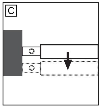
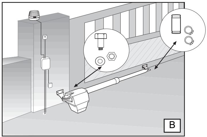
INSTALLING THE DRIVE ARMS

Release the drive. Push the released drive onto the fittings and secure it by using the supplied bolts and rings.
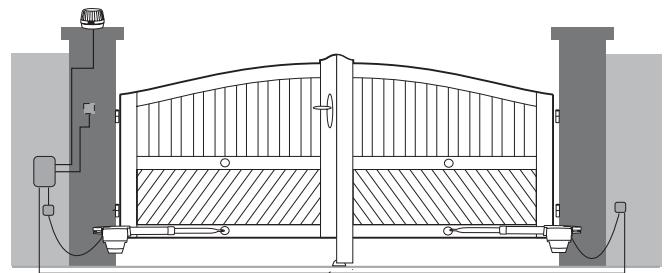
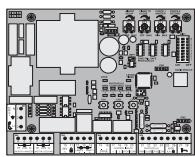
WIRING
The 3-pole connecting cable is approx. 80~cm long and is laid in a curve to the controller or a watertight distribution box located above ground. An approved cable is permanently installed from the distribution box onwards. The capacitor can be connected inside the distribution box or in the controller.
Connection: Connect the capacitor across terminals CL and OP. CL and COM produce rotation direction A. OP and COM produce reversed direction of rotation. Always remember to earth the installation.
MAINTENANCE WORK
The drive mechanism is maintenance free. Check that the gate fittings and the drive mechanism are securely fixed at regular intervals (monthly). Release the drive and check that the gate functions properly. Unless the gate runs smoothly it will not operate correctly with the drive mechanism. The drive cannot eliminate the problems caused by a gate that does not work satisfactorily.
TECHNICAL DATA
Mains supply (Motor) 220 - 240 Volt-1 50Hz
Current consumption 1,3A
Power consumption \~220W
Capacitor 5μF
Max. gate width 2,5m HC280ML/300ML/300MLS
3.5m HC400ML/400MLS
Max.gate weight 200kg
Protection Class I - IP 44
Connecting cable 80cm
Rated Thrust \~250N
Travel Speed approx.20mm/s HC280ML/HC300ML approx.12mm/s HC400ML
Rated operating time 4 minutes
Temperature -20°C to + 55°C
Mains supply (Control) 230V/50-60Hz
Absorbed power 4 Watt
Protection Class (Box) IP44
Declaration of Conformity
Automatic Gate Opener Models HC280ML, HC300ML/MLS, HC400ML/MLS Series are in conformity to the applicable
sections of StandardsEN300220-3·EN55014·EN61000-3·EN60555, EN60335-1·ETS
300 683·EN60335-1:2002·EN60335-2-103:2003·EN55014-1:2000+A1+A2
EN55014-2: 2001 • EN61000-3-2: 2000 • EN61000-3-3: 1995 + A1 • EN 301 489-3,
V1.3.1·EN 300 220-3 V1.1.1·EN 13241-1
per the provisions & all amendments
of the EU Directives 73/23/EEC, 89/336EEC, 1999/5/EG
Declaration of Incorporation
Automatic Gate Opener Models when installed and maintained according to all the Manufacturer's instructions in combination with a Gate, which has also been installed and maintained according to all the Manufacturer's instructions, meets the provisions of EU Directive 89/392/EEC and all amendments.
I, the undersigned, hereby declare that the equipment specified above and any accessory listed in the manual conforms to the above Directives and Standards.
B.P.Kelkhoff
Manager, Regulatory Affairs
Chamberlain GmbH
D-66793 Saarwellingen
Januar, 2006

Dabbaia P. KeckhoH
IMPORTANT ISTRUZIONI PER IL MONTAGGIO E L'USO
PER PRIMA COSA LEGGERE QUESTE IMPORTANTI NORME DI SICUREZZA!

Manager, Regulatory Affairs
Chamberlain GmbH
D-66793 Saarwellingen
Januar. 2006


BELANGRIJKE INSTRUCTIES VOOR MONTAGE EN GEBRUIK
BEGIN MET HET LEZEN VAN DEZE BELANGRIJKE VEILIGHEIDSINSTRUCTIES!

Manager, Regulatory Affairs
Chamberlain GmbH
D-66793 Saarwellingen
Januar, 2006

Dana bica P. Keckhoh
Manager, Regulatory Affairs
Chamberlain GmbH
D-66793 Saarwellingen
Januar, 2006

Barbosa P. Keckhoh


12
13
041ASWG-0100

041ASWG-0098
041ASWG-0175SA
041ASWG-0112
041ADBL-1001SA(HC280/300)
041ADBL-1002SA(HC400)
84333EML
SWG-0490
771EML
041FA277BX
041ASWG-0370