
ECO300KS - Gate Automation CHAMBERLAIN - Free user manual and instructions
Find the device manual for free ECO300KS CHAMBERLAIN in PDF.
User questions about ECO300KS CHAMBERLAIN
0 question about this device. Answer the ones you know or ask your own.
Ask a new question about this device
Download the instructions for your Gate Automation in PDF format for free! Find your manual ECO300KS - CHAMBERLAIN and take your electronic device back in hand. On this page are published all the documents necessary for the use of your device. ECO300KS by CHAMBERLAIN.
USER MANUAL ECO300KS CHAMBERLAIN
Barbara P. Kelkhoff Manager, Reg. Affairs
VEUILLEZ TOUT D'ABORD LIRE CES REGLES DE SECURITE IMPORTANTES

Page 3, Figures 12 A-E
Sécurité: Page 4
Lampe clignotide (option):
Page 5, Figure 13 A-C
Photo cellules:
Page 5, Figure 14 A-F
Page 5, Figure 15 A-B
Mise en Service: Page 6
\section*{Caracteristiques techniques: Page 6}
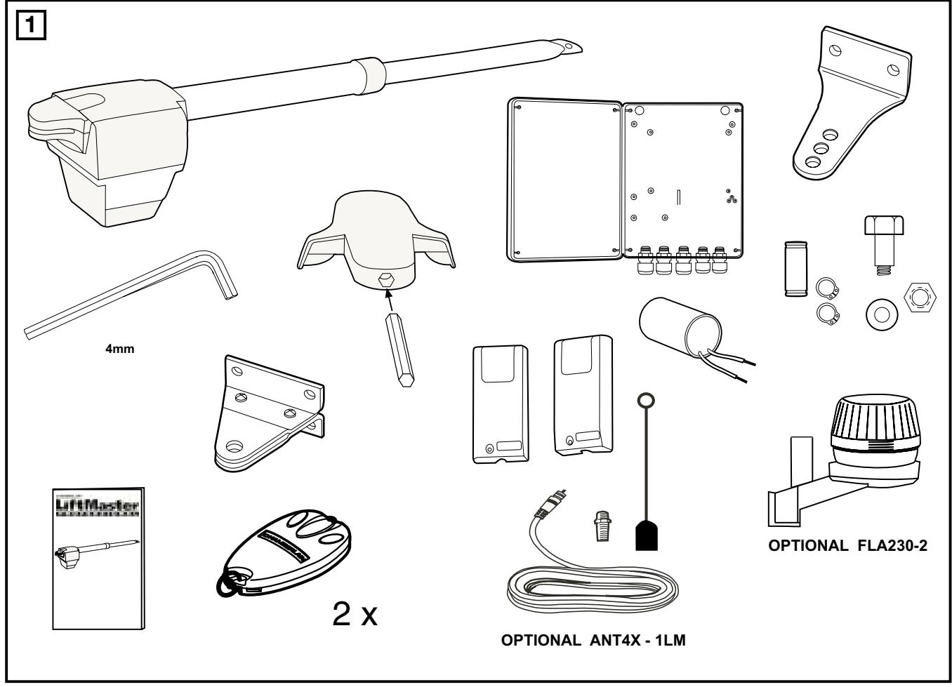
CONTENU DE LA COLI ECO300KS/ECO400KS 1
ARRET D'URGENCE (OPTION)
Manager, Reg. Affairs
PLEASE START BY READING THESE IMPORTANT SAFETY RULES • SAVE THESE INSTRUCTIONS

This safety alert symbol means "Caution" - failure to comply with such an instruction involves risk of personal injury or damage to property. Please read these warnings carefully.

This gate drive mechanism is designed and tested to offer appropriately safe service provided it is installed and operated in strict accordance with the following safety rules.
Incorrect installation and/or failure to comply with the following instructions may result in serious personal injury or property damage.

When using tools and small parts to install or carry out repair work on a gate exercise caution and do not wear rings, watches or loose clothing.

Installation and wiring must be in compliance with your local building and electrical installation codes. Power cables must only be connected to a properly earthed supply.

Any entrapment possibility by the moving wing between wing & walls must be secured with safety edges or IR-sensors.

Please remove any locks fitted to the gate in order to prevent damage to the gate.

After the installation a final test of the full function of the system and the full function of the safety devices must be done.

This drive cannot be used with a gate incorporating a wicket door unless the drive cannot be operated with the wicket door open.

It is important to make sure that the gate always runs smoothly. Gates which stick or jam must be repaired immediately. Employ a qualified technician to repair the gate, never attempt to repair it yourself.

Keep additional accessories away from children. Do not allow children to play with pushbuttons or remote controls. A gate can cause serious injuries as it closes.

Disconnect electric power to the system before making repairs or removing covers.
A disconnecting device must be provided in the permanently-wired installation to guarantee all-pole disconnection by means of a switch (at least 3mm contact gap) or by a separate fuse.

Make sure that people who install, maintain or operate the gate drive follow these instructions. Keep these instructions in a safe place so that you can refer to them quickly when you need to.

The full protection against potential squeeze or entrapment must work direct when the drive arms are installed.
Contents: General advice on installation and use:
Content of the carton: Page 1
figures 1+2
Before you begin: Page 2
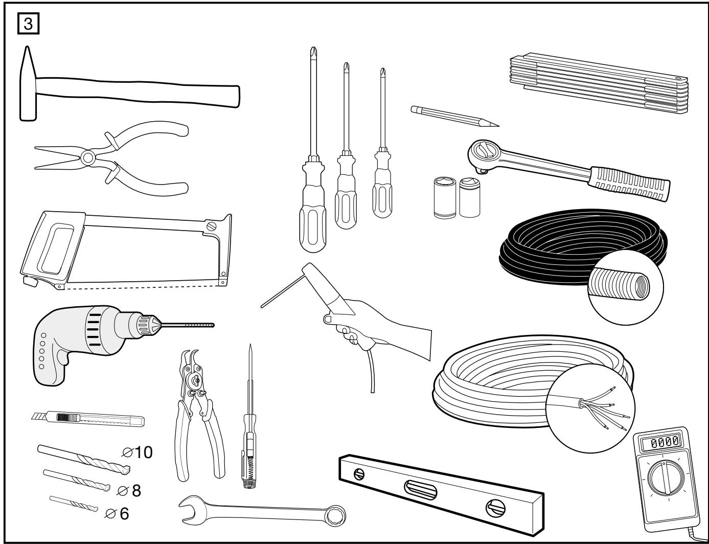
Checklist: Page 2, figure 3
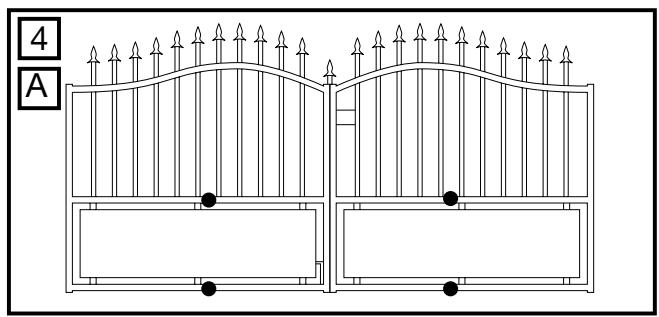
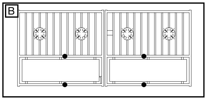
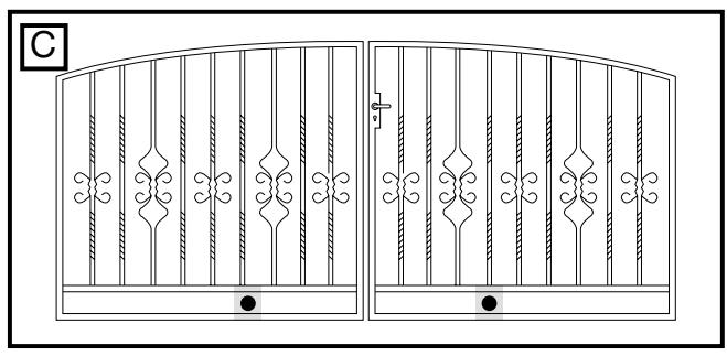
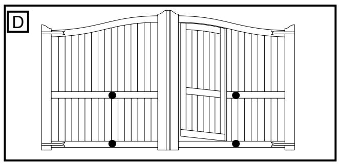
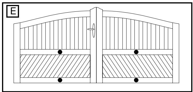
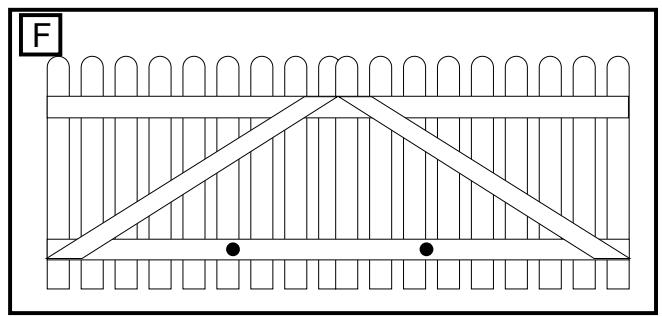
Gate types/installation height:
Page 2, figure 4 A-F
Gate configuration:
Page 2, figure 5 + 6A - E
Gate stops:
Page 2, figure 7
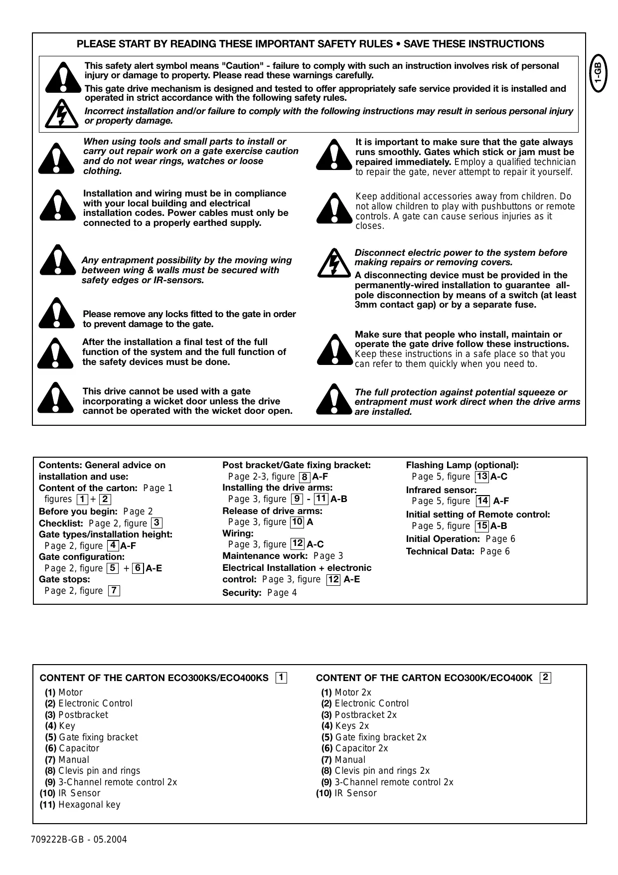
Post bracket/Gate fixing bracket:
Page 2-3, figure 8 A-F
Installing the drive arms:
Page 3, figure 9 - 11A-B
Release of drive arms:
Page 3, figure 10 A
Wiring:
Page 3, figure 12 A-C
Maintenance work: Page 3
Electrical Installation + electronic
control: Page 3, figure 12 A-E
Security: Page 4
Flashing Lamp (optional):
Page 5, figure [13]A-C
Infrared sensor:
Page 5, figure 14 A-F
Initial setting of Remote control:
Page 5, figure 15A-B
Initial Operation: Page 6
Technical Data: Page 6
CONTENT OF THE CARTON ECO300KS/ECO400KS 1
(1) Motor
(2) Electronic Control
(3) Postbracket
(4) Key
(5) Gate fixing bracket
(6) Capacitor
(7) Manual
(8) Clevis pin and rings
(9) 3-Channel remote control 2x
(10) IR Sensor
(11) Hexagonal key
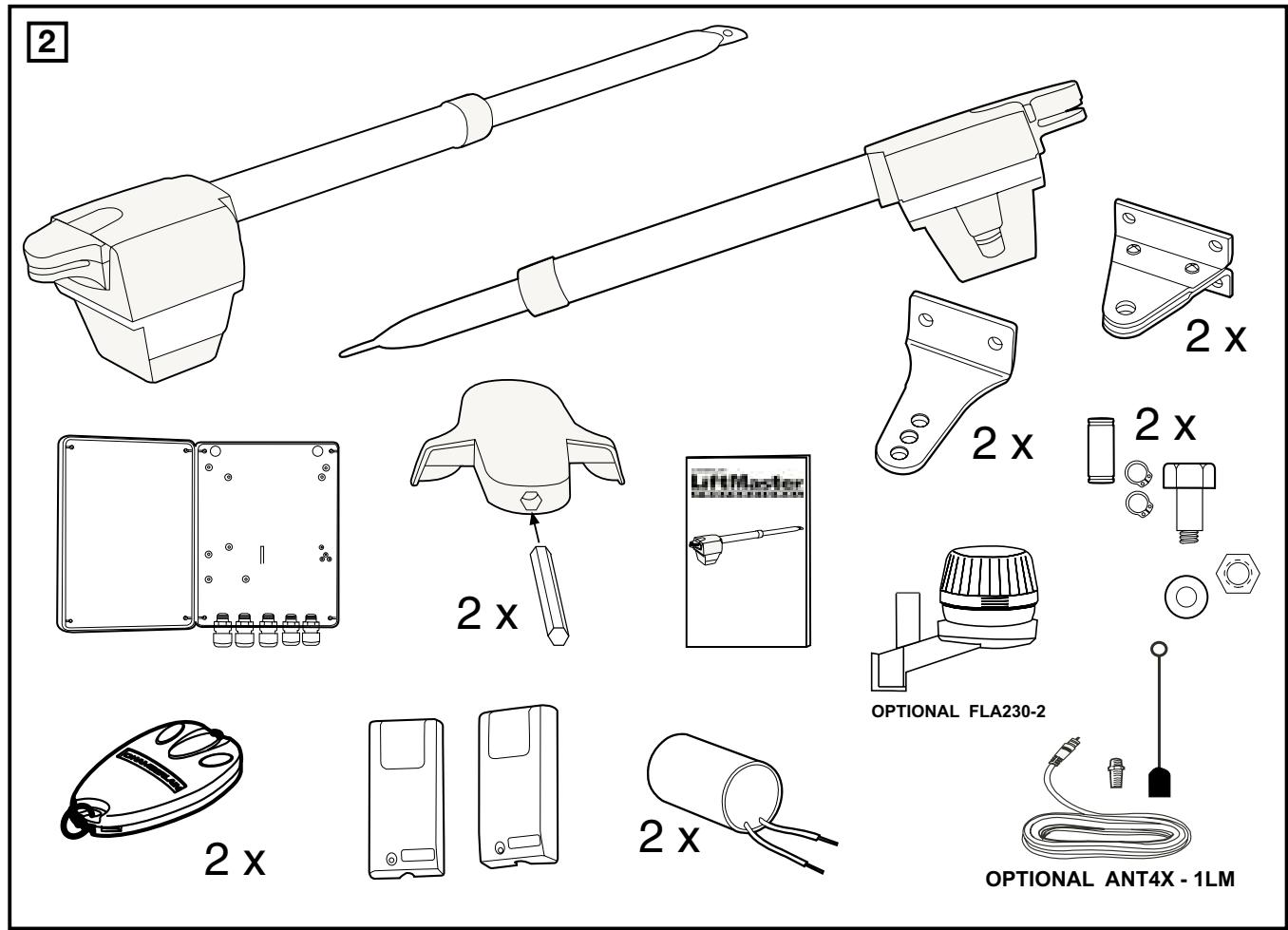
CONTENT OF THE CARTON ECO300K/ECO400K 2
(1) Motor 2x
(2) Electronic Control
(3) Postbracket 2x
(4) Keys 2x
(5) Gate fixing bracket 2x
(6) Capacitor 2x
(7) Manual
(8) Clevis pin and rings 2x
(9) 3-Channel remote control 2x
10) IR Sensor
BEFORE YOU BEGIN
The drive mechanism needs room to the side permitting correct installation of drive arms. Please make sure that this is available. Gates affected by high wind loads must also be protected by an (electric) lock.
There are many factors to consider when choosing the right drive mechanism. Assuming that a gate functions properly, "startup" is the most difficult phase, once the gate is in motion, significantly less force is usually required to move it.
- Gate size: Gate size is a very important factor. Wind can brake or distort the gate, thereby increasing the amount of force needed to move it considerably.
- Gate weight: The weight of the gate in not as relevant as the size.
- Effect of temperature: Low outdoor temperatures can make initial startup more difficult (changes in the ground, etc.) or even prevent it. High outdoor temperatures along with frequent use can trigger thermal protection prematurely (approx. 135^ ).
- Operating frequency/operating time: Drive mechanisms are designed for a maximum operating time (running time) of approximately 30% (e.g. 30% during any one hour).
IMPORTANT: The drive mechanism is not designed to operate continuously at its maximum operating time (non-stop operation). Otherwise the drive mechanism becomes too hot and switches off until it cools down to the switch-on temperature. The outdoor temperature and the gate are important parameters that affect the actual operating time.
INSTALLATION CHECKLIST - PREPARATIONS
Check the carton contents and read the instructions carefully. Make sure your gate equipment operates perfectly. The gate must run evenly and smoothly and must not stick at any point. Remember that the ground level may be several centimeters higher in winter. The gate must be stable and as free of backlash in order to prevent any unwanted movement. The more smoothly the gate wing runs, the more sensitive the force adjustment must be.
Write down any materials you still need and obtain them before starting to install. Heavy-duty plugs, bolts, gate stops, cables, distribution boxes, tools, etc.
GATE TYPES
The gate type determines the location where the drive mechanism is installed. If the gate stop is on the ground, the drive mechanism must also be installed at a height that is as low as possible so that it cannot twist the gate. Use only parts of the gate frame for fixing purposes.
For steel gates, the gate fitting must be attached to the main frame. If you are uncertain whether the available support is sufficiently stable, reinforce it.
In the case of wooden gates, the gate fitting must be bolted through. It is advisable to fit a plate from the outside so that the fixing brackets cannot become loose over time. Thin wooden gates must also be reinforced in order to withstand the stresses encountered.
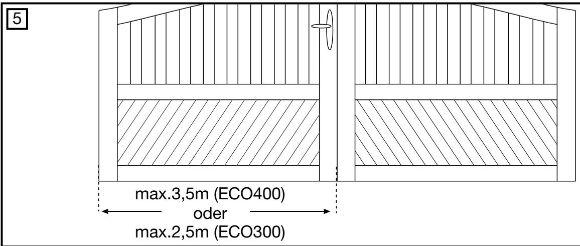
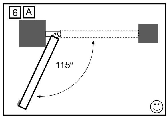
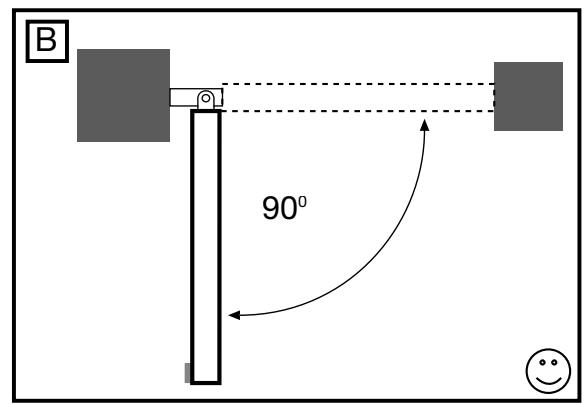
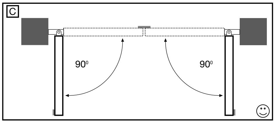
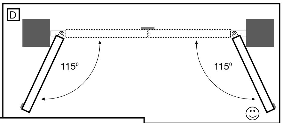
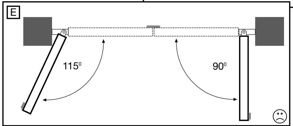
GATE CONFIGURATION
How far must the gate wing open?
90 degrees or up to 115 degrees. An opening angle in excess of 115 degrees is possible but is not recommended. Reason: the drive mechanism always runs at the same speed. The further the gate has to be opened, the faster the wing must travel. Movement becomes more erratic and this subjects the fittings and gate to extreme stresses. Different opening angles cause one motor to reach its destination first, but continues to run, thereby forcing the gate up against the gate stop until the other motor eventually reaches its end position.
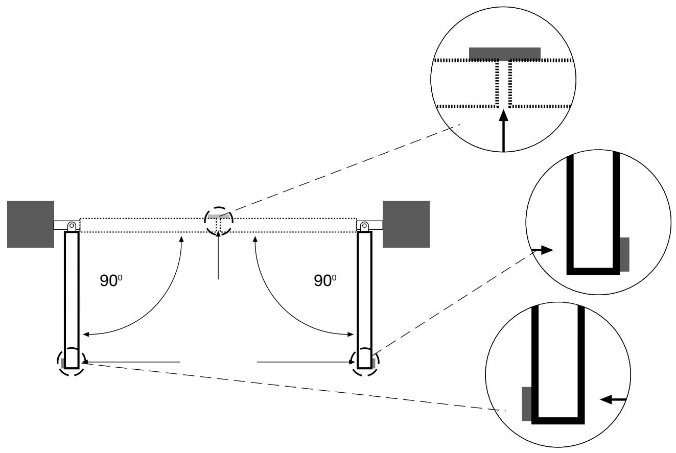
GATE STOPS
A SWING GATE NEEDS A FIXED GATE STOP IN BOTH THE OPEN AND CLOSE POSITIONS. Gate stops save wear and tear on the motor, gate and fittings. Operating a gate without fixed limit stops results in poor performance. It is often dangerous, leads to premature wear and voids your warranty!
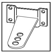
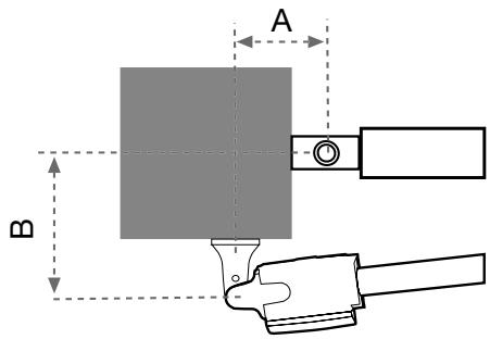
POST FIXING BRACKET
Choosing the correct location for the post fixing bracket has a decisive impact on the subsequent functioning of the system. It determines the distance between the motor's centre of motion and the gate's centre of motion and hence the opening angle. These dimensions are referred to as dimension A and dimension B. Do not underestimate the effect that these dimensions have on correct functioning and running. Try to achieve the best possible dimension for your opening angle that is suitable for all circumstances. See Table for dimensions A/B.
If the post is not wide enough, an extension piece must be fitted to it. If the post is too thick, cut out part of it to make it thinner or offset the gate.
To obtain ideal dimensions, it may be necessary to shorten or lengthen the supplied hinge plate. In the case of gates that are to be custom made, if the gate hinges are fitted on the posts appropriately, it is possible to influence dimensions A and B. Before the final mounting dimensions are determined, you should always check whether or not there is any possibility that the corner of the drive mechanism will hit the post as the gate swings.
INSTALLATION: The drive mechanism exerts considerable force against the post. Usually, acceptable mounting dimensions are obtained if the supplied hinge plate is welded directly onto the post. In the case of thick stone or concrete posts, the hinge must be welded to a base plate and attached so that the plugs cannot work loose during operation. Heavy-duty plugs where a threaded rod is bonded into the masonry stress-free are more suitable for this purpose than steel or plastic straddling plugs. In the case of brickwork pillars, bolt a relatively large steel plate that covers several bricks on to it and then weld the hinge plate to it. An angled plate attached over the corner of the post is also a good means of fixing the operators.
GATE FITTING
The gate fitting must be installed so that it is horizontal relative to the post bracket. The distance between the gate bracket and post bracket is referred to as the "arm span". When the gate is closed, the drive mechanism is 95% extended. When the gate is opened, the drive mechanism is 5% extended. Fully retracting or extending the plunger/spindle in operation (with gate) damages the drive mechanism and voids the warranty. It is absolutely imperative to comply with the required arm span under all circumstances!
For steel gates, fixings should be welded on or through bolted. When through bolting the gate, use large washers or a plate on the other side. The drive mechanism exerts an extremely high force on this joint.
Fixings must be through bolted for wooden gates. It is recommended that metal plates be fitted on either side of the gate, to prevent the fixings from becoming loose.
RELEASE
The drive mechanism can be released. The gate can then be opened and operated manually (power failure). With a new drive mechanism, the release action may sometimes feel stiff/jerky. This is normal and has no effect on function.
Release and Engage
Place the hexagonal key into the hole provided in the cover. Engage or disengage the motor.
INSTALLING THE DRIVE ARMS

Release the drive. Push the released drive onto the fittings and secure it by using the supplied bolts and rings.
If the centre or inner hole, on the hinge plate, is used to fix the post fixing bracket you MUST cut away the remaining section of the hinge plate before activating the arms. Failure to do so will result in breaking the fixing bracket.
Do not use a hammer when you mount the operator on the bracket.
WIRING
The 4-pole connecting cable is approx. 80~cm long and is laid in a curve to the controller or a watertight distribution box located above ground. An approved cable is permanently installed from the distribution box onwards. The capacitor can be connected inside the distribution box or in the controller.
Connection: Connect the capacitor across terminals CL and OP. CL and COM produce rotation direction A. OP and COM produce reversed direction of rotation. Always remember to earth the installation.
MAINTENANCE WORK
The drive mechanism is maintenance free. Check that the gate fittings and the drive mechanism are securely fixed at regular intervals (monthly). Release the drive and check that the gate functions properly. Unless the gate runs smoothly it will not operate correctly with the drive mechanism. The drive cannot eliminate the problems caused by a gate that does not work satisfactorily.
ELECTRONIC CONTROL
The control board should be the last item to be connected, i.e. mounting the motors, laying the necessary cable and fitting light barriers or contact strips. If installation is to be performed in a permanent location, a means of disconnecting the equipment from the mains supply with a contact clearance of at least 3mm is needed (master switch).
Please note: in these instructions, relay contacts are designated NC (normal closed) or NO (normal open).
- NC contacts are closed and open
- NO contacts are open and close
Humidity and water will destroy the control board. Always make sure that water, humidity and condensation cannot enter the control box. It is vitally important that all openings and cable glands are sealed so that they are watertight.
Materials required (details vary depending on particular application)
Distribution box
- Buried cable, at least 1.5 ~mm^2
Buried cable, at least 0.5mm^2
- Screws
- Wall plugs
ELECTRICAL INSTALLATION
Installing the electronic control board: the motor control board is a microprocessor-controlled electronic appliance featuring state-of-the-art technology. It is equipped with all the connecting options and functions needed to guarantee safe operation. An overview of the wiring plan is shown in fig. 12D. The control box incorporating the motor control board should be installed with the cable intakes pointing downwards fig. 12A. It should not be continuously exposed to direct sunlight. The electronic equipment enables the pull and push forces to be set with great accuracy. If installed and set correctly, the gate/door can be stopped manually. When in motion, the gate/door can be stopped at any time by operating the remote control, the push-button or the key-operated switch.
The gate/door wing must be fitted with a robust end stop for the 'OPEN' and 'CLOSED' positions as the gate/door drive has no limit switches.
Current distribution: the cable leading from the drive arm must be laid in a standard watertight distribution box. A permanently installed cable can be laid from the distribution box to the control unit. It is often possible to wire the drive, which is fixed beside the control unit directly to the box. Never install distribution boxes underground.
Generally speaking, the following minimum cable cross-sectional areas must be adhered to:
100-230Volt 1.5mm² or more
0-24Volt 0.5mm^2 or more
Tips: Bell wire is often problematic in practical use because it loses too much voltage if long lengths of wire are used. Segregate the cables in cable trunking, i.e. motor cable and light barrier cable, especially in the case of key-operated switches and ON switches (from the house wiring system) to prevent interference where long lengths of cable are used.
OVERVIEW OF CONNECTIONS
Motors: connect the control unit exactly in accordance with the overview of connections. The gate/door wing, which opens first, must be motor 1 (M1) and when it first moves it must OPEN the gate/door. If it closes the gate/door, swap terminal 6 with terminal 8 or, in the case of motor 2 (M2), swap terminal 9 with terminal 11.
The capacitor supplied as standard must be installed between cables 6 and 8 and 9 and 11 (for space reasons, the capacitor can also be installed in a distribution box).
Make sure that its terminals are properly connected and that there is a good electrical connection. The capacitor determines the force which the motor subsequently develops.
OVERVIEW OF CONNECTIONS
Description of terminal occupancy
| Mains cable connection: | |
| Terminal 1 | N (blue) |
| Terminal 2 | PE (green/yellow) |
| Terminal 3 | L1 - 230 V (black) |
| Flashing lamp connection: | |
| Terminal 4 | L(230V) |
| Terminal 5 | |
| Motor connections: | |
| Terminal 6 | First motor (M1):M1 direction of OPEN (brown/black)(+ capacitor) |
| Terminal 7 | N (blue) |
| Terminal 8 | M1 direction of CLOSED (black/brown)(+ capacitor) |
| Terminal 9 | Second motor (M2):M2 direction of OPEN (black/brown)(+ capacitor) |
| Terminal 10 | N (blue)M2 direction of CLOSED (brown/black)(+ capacitor) |
| Terminal 11 | |
| Infrared light barrier | |
| Terminal 12 | photocell (NC) active when closing |
| Terminal 13 | COM |
| Terminal 14 | photocell (NC) active when opening(without light barrier -jumper between 12, 13 and 14!) |
| Description of terminal occupancy | |
| EMERGENCY STOP FUNCTION | |
| Terminal 15 | COM |
| Terminal 16 | Stop (NC) with emergency stopswitch jumper between 15 and 16 |
| Control line connection | |
| Terminal 17 | External push-button (NO) motor 1 (ped. function) |
| Terminal 15 | COM |
| Terminal 18 | External push-button (NO) motors 1+2 |
| Electric lock connection | |
| Terminal 19 | Distribution voltage 12 V AC |
| Terminal 20 | Distribution voltage 12 V AC |
| Connection for additional equipment &light barrier | |
| Terminal 21 | Distribution voltage 24 V AC (500 mA max.) |
| Terminal 22 | Distribution voltage 24 V AC |
DESCRIPTION OF JUMPER
JP1: MOTOR
OPEN: (without jumper): only for single-wing gates (only motor 1 operating).
CLOSED: (with jumper): only for double-wing gates (motors 1 and 2 operating).
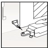
JP2: channel 2 radio receiver
If both learning channels are put together (A-side), the memory capacity of the radio receiver doubles in size. The gate can then only be fully opened. The "Pedestrian" function is no longer available. A-side: (optional) receiver channel 2 is connected up to receiver channel 1.
B-side: (standard) the
two radio receiver channels work separately from one another.
SAFETY
FLASHING LAMP (OPTIONAL)
Usage of a flashing lamp is mandatory. It serves a safety-related purpose in that it warns persons in the vicinity of the gate/door that the given gate/door is moving. The flashing lamp is fixed using screws and wall plugs. The buried cable has to be run up to connect with the lamp. Generally speaking, it is installed at the highest possible point (on a pillar). Cross-sectional area: 0.75mm^2 , 3-pole voltage: 230 Volt/AC.
INFRARED SENSOR
The IR Sensor provides additional safety to the gate/door and must be used. Its point of installation depends on the design of the given gate/door. Generally speaking, the light barrier is fitted at around knee height, approx. 35 cm above ground level. IR Sensors comprise of a transmitter element and a receiver element, which must be located opposite one another. A screwdriver can be used to open the light barrier housing (plastic). The IR Sensor is fitted to the wall with small screws and wall plugs. Usage of a single set of IR Sensors is a minimum requirement; we recommend using two sets of IR Sensors (and other safety facilities if necessary).
It is possible to connect the IR Sensor as described below. Active when 'OPENING' (terminal 14) or active when 'CLOSING' (terminal 12). The instructions describe how to connect a single IR Sensor and therefore uses both fuse inputs, i.e. active in both directions. DIP switch 4 on the control unit controls the door wing's response if the light beam is interrupted while the gate/door is closing. An active IR Sensor (only) stops the gate/door or an active IR Sensor reverses the direction of the gate/door.
The transmitter element needs a 2-pole cable, the receiver element a 4-pole one. Cable cross-sectional area: 0.5mm^2 or more. Voltage: 12/24Volt AC/DC. Terminals (12-13-14) (22/23).
EMERGENCY STOP (OPTIONAL)
If a switch is connected, it can be used to stop or disable the installation. This immediately interrupts movement of the wing. Depending on the level of safety needed, the contact can also be connected on the gate/door to the IR Sensor's contacts. This immediately stops any wing movement.
In dead man's operating mode, a gate/door can be operated without safety facilities insofar as the operator has a clear view of it during the whole period of operation. There are 3 DIP switches located on the upper part of the control unit. Set DIP switch 2 to the ON position. The control unit only functions in this case if a signal can be continuously transmitted via the handset, key-operated switch or push-button. Any interruption in the signal causes the gate/door to stop and the next signal sent moves it in the opposite direction.
CONTROL LINES
It is possible to open only one gate/door or both gates/doors. This function is also possible when using the radio remote control. See initial setting of remote control. The test button on the control unit always switches on both motors. If the installation has overlapping wings, the wing delay must be set. Wings that do not overlap may not close simultaneously - risk of persons trapping themselves (see 'Description of Potentiometer' section).
INSTALLATION OF KEY-OPERATED SWITCH (OPTIONAL)
Cable connections as per wiring plan.
ELECTRICAL LOCK (OPTIONAL)
An electrical lock can be connected to terminals 19 - 20. Output voltage: 12 V AC. See 'DIP Switch Settings' section too!
ANTENNA (OPTIONAL)
An external antenna is not a mandatory requirement. A short antenna is located on the control unit's radio adapter. Should the range of the remote control need to be extended, fit an external antenna compatible with 433 MHz (the ANT4X-1LM model incl. 750 Ohm coaxial cable). It has to be connected via the radio adapter on the control unit (see 'Control Unit Instructions' section). The best location for an antenna is as high up and as far away from electrical equipment as possible. The short cable antenna that is supplied as standard and pre-connected may then no longer be used.
DESCRIPTION OF DIP SWITCHES
The DIP switches control the general functions of the installation:
Automatic closing or default
- Dead man's operating mode
Electric lock function
Response of light barrier
| DIP switch 1 | ON | Automatic closing |
| OFF | Default | |
| DIP switch 2 | ON | Dead man's operating mode |
| OFF | Default | |
| DIP switch 3 | ON | Electric lock function |
| OFF | Default | |
| DIP switch 4 | ON | Light barrier (for closing) stops the gate/door |
| OFF | Default light barrier (for closing) opens the gate/door |
DESCRIPTION OF POTENTIOMETER
- Force M1 Force M2:
Adjust the force with which the door operates for each wing separately. The rotary potentiometer is used to make fine gate/door adjustments.
Should the force generated by the moving wing at its closing edge exceed 400N , additional safety features (IR sensors, contact strips) must be fitted. Any safety features fitted must comply with the appropriate standards (Europe: EN60335-1). See 'Safety Rules' section too.
- PAUSE
This function is only active if DIP switch 1 is set to ON. It adjusts the time for which the gate/door is kept open before it closes again. Adjustable: 8-200 seconds.
- OPEN-CLOSED
Adjust the maximum running time of the wings. Set the running time to approx. 30% and then test. Correct adjustment is obtained when the drive continues to run (hum) against the end stop for 3-5 seconds each time in one complete cycle. This is necessary because the required running time is affected by external influences and it must be ensured that the end position is reliably reached (wind, temperature, changes in ground conditions). This is why end stops in the OPEN and CLOSE directions are stipulated as being mandatory.
Adjustable: 7-60 seconds
WING DELAY
Controls the wing delay in the case of installations with overlapping wings. Wing M1 opens first and closes last. A delay must always be set in order to make sure that no one can trap themselves between two closing wings.
Adjustable: 0-35 seconds
DESCRIPTION OF LEDs
LED 1 red Monitors the light barrier for door closing. LED ON = OK
LED 2 red Monitors the light barrier for door opening LED ON = OK
LED 3 yellow Monitors the emergency stop contact ON=OK
LED 4 green Indicates signals from key-operated switches, push Buttons or radio. Single-wing gate/door opening function ON = signal present.
LED 5 green Indicates signals from key-operated switches, push Buttons or radio. Both-wing gate/door opening function ON = signal present.
LED 6 red Flashes slowly = OK Flashes quickly = check all connections to the motors, capacitor, flashing lamp and remove any humidity from terminals.
DESCRIPTION OF FUSES
F1 5.0A Main fuse: Protects the entire control unit and the motors. Never replace this fuse by one with a higher rating.
F2 0,5A Secondary fuse for 24V output.
F3 2,0A Secondary fuse for electric lock 12 V output. Please bear in mind the power requirement of the electric lock you use.
F4 0,315A Secondary fuse for logic circuitry: push Buttons, emergency stop, light barrier, receiver.
TEACHING THE REMOTE CONTROL
Up to 15 remote controls can be programmed on each self-learn channel. In the case of large installations it is advisable for organizational reasons, to use an external receiver or a key-operated switch or a code lock, which should be installed at the entrance.
The radio receiver plugs in on the side and has two small self-learn buttons.
The radio remote control is licensed by the Post + Telecommunication Office and costs nothing to operate. It works on the basis of a private security code that is pre-programmed via computer. Your gate/door drive can thus only be activated by a correspondingly coded handset. The range obtained depends on the given local environment. The receiver element of the motor control has an integrated self-learn function. It can be set to the handset's pre-programmed code by pressing the self-learn push-button.
The control unit has two self-learn channels and is therefore able to open or close one gate/door or both gates/doors simultaneously via appropriate operation of the handset. Should, for instance, channel 1 (2) receive the handset's remote control code, only one wing will be opened. If you teach the remote control on channel 2 (1), you will be able to open both wings via the appropriate push-button. To memorize the code all you need do is press the button of your choice on the handset and keep it depressed while, at the same time, briefly pressing the self-learn button on the electronic unit with the other hand. Repeat this procedure for all other transmitters.
DELETION OF REMOTE CONTROL CODE
Press the appropriate self-learn button (1 or 2) on the receiver control board for approx. 10 seconds until the self-learn LED extinguishes. The codes previously 'learned' allocated to the given self-learn button have thus been deleted.
REPROGRAMMING
For reprogramming purposes, the coding procedure mentioned above should be repeated for all the remote controls in use and/or their appropriate operating buttons.
The radio remote control's range varies according to the given local environment. Keep the push-button on the handset depressed until such time (approx. 2 seconds) as the gate/door is seen to move.
Your radio remote control is digitally coded, i.e. accidental operation of the gate/door drive is more or less impossible.
INITIAL OPERATION
Proceed carefully and deliberately. Do not rush the process of making the basic settings. It may take up to 30 minutes to complete initial settings. If applicable get help from a second person so that changes on the control unit can be made more easily (power OFF or ON).
- Connect the control unit including the safety inputs.
- Check the LEDs.
- Move the gate/door to a half-opened position and engage it, then press the test button. Both wings must then open. If one wing closes instead of opening, the terminals on the given wing's motor have been connected incorrectly and the motor cables for the relevant motor must be swapped round (see connections). The cables to which the capacitor is also connected are the ones that need to be swapped round. They determine the direction in which the motors run. Then repeat the entire process until both wings open when they first move. Important, always switch the power off to do this.
- If both wings open when they first move once the control unit has been connected, proceed as follows.
- Interrupt the power supply to the control unit and reconnect it after a few seconds. Close both gate/door wings manually and engage both wings.
- Adjust all the potentiometers to 30% and make sure that DIP switch 1 is set to OFF (down).
- Then use the test button to switch on the control unit and observe what happens. Close the gate/door again by using the test button WITHOUT having made any adjustments to the settings. If the gate/door does not close completely by itself, release the drive and close it manually after switching off the control unit.
- Then adjust the potentiometer to a different (higher) value in line with the value suggested by practical experience from trial operation (e.g. increase running time, correct force, wing delay). Then make a second trial and repeat the procedure above closing the gate/door first with the test button before making any further settings.
- Once all settings have been made, check that the light barriers, push Buttons, flashing lamp, handset, accessories etc. function correctly. If you require automatic closing, modify the setting of the DIP switches and adjust the potentiometer for a pause.
- Show anyone who has to deal with the gate/door how the gate/door moves, how the safety functions operate and how the drive can be actuated manually.
TECHNICAL DATA
Mains supply (Motor) 220 - 240Volt-/ 50Hz
Current consumption 1,3A
Power consumption 220W
Capacitor 5uF
Max. gate width 2,5m ECO300K/300KS
3.5m ECO400K/400KS
Max. gate weight 200kg
Protection Class I - IP 44
Connecting cable H07RN-F / 80cm
Rated Thrust 250N
Travel Speed 20mm/s
12mm/s
Rated operating time 4 minutes
Temperature -20°C to + 55°C
Mains supply (Control) 230V/50-60Hz
Absorbed power 4 Watt
Max. load 1100W
Protection fuses 1 (5A)
Protection Class (Box) IP54
Declaration of Conformity
Automatic Gate Opener ....Models ECO300K/300KS/400K/400KS
is in conformity to the applicable
sections of Standards.. EN300220-3, EN55014, EN61000-3,
EN60555, EN60335-1, & ETS 300 683
per the provisions & all amendments
of the EU Directives 73/23/EEC, 89/336EEC
Declaration of Incorporation
Automatic Gate Opener Models ECO300K/300KS/400K/400KS, when installed and maintained according to all the Manufacturer's instructions in combination with a Gate, which has also been installed and maintained according to all the Manufacturer's instructions, meets the provisions of EU Directive 89/392/EEC and all amendments.
I, the undersigned, hereby declare that the equipment
specified above and any accessory listed in the manual
conforms to the above Directives and Standards.
THE CHAMBERLAIN GROUP, INC.
Elmhurst, IL 60126
USA
June, 2003


Barbara P. Kelkhoff
Manager, Reg. Affairs
NEJPRVE SI PRESTU TATO DULEZITÁ PRAVIDLA BEZPESNOSTI

ELEKTRICKÁ INSTALLACE
Manager, Reg. Affairs
Barbara P. Kelkhoff Manager, Reg. Affairs
KEZDJE A JELEN FONTOS BIZTONSÁGÍ SZABÁLYOK ELOLVASÁSÁVAL

A DOBOZ TARTALMA ECO300KS/ECO400KS 1

A DOBOZ TARTALMA ECO300K/ECO400K 2
Manager, Reg. Affairs
PRE POSETKA PROSITAJTE OVA VAZNA PRAVILA BEZBEDNOSTI

Ovi symboli upozorenja označavaju rijec "Pažnja!", poziv za obracanje pažnje, jer njihovo nepostivanje moze prouzrokovati ostećenje ljudskog zdravlja ili materijalnu šetu. Molimo da pročitate ova upozorenja pažljivo.
Ovaj pogonski mehanizam za kapiju konstruiran je i testiran takdo prilikom instalacije i upotrebe uz tocno postivanje.
pravila bezbjednosti osigurava primjerenu bezbjednost.
Manager, Reg. Affairs
PER PRIMA COSA LEGGERE QUESTE IMPORTANTI NORME DI SICUREZZA!

Manager, Reg. Affairs
BEGIN MET HET LEZEN VAN DEZE BELANGRIJKE VEILIGHEIDSINSTRUCTIES!

NOODSTOP (OPTIONEEL)
.1999/5/EC, 73/23/EEC, 89/336/EEC
Manager, Reg. Affairs
COMECE POR LER ESTAS NORMAS DE SEGURANÇA IMPORTANTES


Manager, Reg. Affairs
PROSZE ROZPOCZAA OD PRZECZYTANIA TYCH WAZNYCH ZASAD DOTYCZACYCH BEZPIECZENTWA


INFORMACJE POCZATKOWE
INSTALACJA WYLACZNIKOW KLUCZOWYCH
Manager, Reg. Affairs
IPEED HauJOM PABOT IPOUHTAITE 3TN BAXHBIE IPIPABUNIA TEXHINK Be3OPIACHOCTN


3Tn npdynpexkaioe cmbolb o3Haayot "BHMHne", obaeHne K Baewemy BHMHIO, TAK kak nx Hec6noJeHne MORI 6bl npuHHb Tb bpe 3doPobBIO yelOBeka nII MaTePnaIbHbI yuep6.
IoxayncTa, BHNMaTeNbHO npOHTaTe 3TN npEpynpExHn.
Данны пивов БорOT сКОнстурован и OTТСТИРов ТAKИМ образим,ЧTOБП пи CBоЕ уCTAHOBKE И NCПЛьЗВОВАпIM (при ТочHOM CO6ЛЮDEнIN праВЛ TExHUN 6e3ONaCHOCHT) ON ppeДОCTaBLJN 6bl ПОЛьЗВATEJILO OTHOCITELBHyIO 6e3ONaCHOCtB.
Itorom Hec6nOeHnHaCToAunx npaBnTexnK 6e3OnacHOCTm MOKeT 6bITb Bpe, npuHHeHbI 3dOpOBbIO IIOe nn MaTePnaJbHbYuep6.


При маниулцяс x Инструмент am n Meлкимп acstamn DeiCTbYte C OSTOPOKHOCtBu n He Hocnte KOnbua (pepcTHN), cacbl n Cbo6oJHyO OdeJy (ecnHa Bopotax ocyuieCTBJIaOTcra pa60tbl no nx yctahOBke n peMOHTy).
3JNeKtpponpoBOKy Heo6XODIMNo pOKnlaDbIbAtb B COOTBETCTBNN C MeCTHbIMN CTpOHTeNbHbIMN HOpMaMn INHCTpyKUHN, OTHOCaUIMMCRA 3JNeKtpponpoBOKe. POnkJIIOUHeHne 3JNeKtpuueCKORO KaBeJI K npaBUNHO 3a3EmLeHHo CETn MOxET OCUSeCTBIArTB JINsB abTOPn3OBAHbHI pa60THNK - 3JNeKtpNK.

IpnMOHTaKe Heo6xOdmo PnHnTb BO BHMaHHe ONaCHOCTb 3axatna MExJy nepeMeuAeMoY aCtBIO BOpOT N OkpyKaIOUmm YactAmN 3daHnHa, HapPmep: CTehOI.

ДяТOrO,УTO6bI BOCIPENTCTBOBaTb BO3HnKHOBeHIO NOBpeJdeHn, NOXaJIyNCTa, YdaJInte N3 BOPOT BCE BMOHTIpOBaHHbIe B HIX 3aMKN.

Iocne yctaHOBKn Heo6xOdImo IpoBepntb MexAHn3M Ha npaBnIbHocTb erO HacTPOkN, a TaKKe npuBOd, cnCTembl 6e3OpaNcHocTn n abapuHoro OT6JOKnPoBaHnHa NpEdmet nx npaBnIbHoro fynHKUOnHnPoBaHn.

EcIn B BOpToX yCTaHOBJIeHbI DBePn IJn IpOxoJa,TO npINBOHOm MExaHN3M HeJIb3A3nyCTNTb INN OCTaBNTb erO BKIIIOUeHHbIM Do TEX NOp, POKa BOpTa He 6yDt DOJNXhbIM O6pa3OM 3aKpbTbI.

Baxho, yTo6bI nepeMeueHne BOpOT 6bIIO 6bl NOCToHHO rnaKm. BOpota, KOtOpbIe 3aKInHrTa Hn 6byT 3aeDaT, Heo6xOIMo HemeJeHHO OTpeMOHTnpoBaTb. He np6yIte peMOHTnpoBaTb BOpOT caM. ObaTntecb 3a NOMOsbI K cneuaNIncTy.

Дононтельные усточаразмecтite тak,чTOбыОн He 6bЛIN DoCTyHbI DeTAM. He no3BOJnTe DeTAM,чTOбы Oи MaHInyInpoBaJI C KHOKNKaMn I NDCtAHUOnHHbIM YnpaBneHnEM.ЗakpbIBaIOUmeCBA BOPTa MOrTy PnUHNHtB TЯжелble paHEnHn.

PnOcUeCTBHeHn pa6oT no yXody, HAnpImep: npOuNCTKe, ABTOMaTHueCKn ynpAblReMbIe yCTpoiCTBaDOnKhBi 6bItb OTKnIOUeHbI n3 CETn 3JIeKTponITaHn.
Y JeCTKO NODKJIIOUeHHoJ 3JIeKTPoPnPoBODKn Heo6xOIMO NOMHHTb 06 yCTpOcTBe pa3MbIkaHnJa DnA TORO, YTO6bI BO BCEX NOLAX OTKJIIOUeHHa 6blNo 6bl rapaHTnpoBaHO OTKJIIOUeHne npn NOMOuN pepeKJIIOUaTeJIa (pa3MbIkaHne KOHTaKTOB He MeHee 3 MM) nII npn NOMOUs OTeJeBHorO ppeOxApaHInTeJIa.

Obecepeythe, yTo6bI Te Iina, KOtOpbIe ocUeCTBIAHOT MOHTaX, yXoN o6cbNyKINBaHne npINbOda, co6JIIOaII Tpe6OBaHn HAcTOnuei HcTpyKUn. IHcTpyKUnIO pa3MeCTNTe B TaKOM MeCTe, Ige 6bl OHa 6blJa 6blctpo DOCTyInHa.

Iocne MONTaxa npnbOda donxHa 6bItb 6e3ycNoBHO oecneheha oxpana MeCT, B KOTOpbIX cyuecTByET yrpo3a BO3HNKHOBeHn yUn6OB n Iope3OB.
CopejkaHne:O6uHne yKa3aHnno MoTaJky n 3KcNJIyatauHn:
CopejxHmoeAunka: pncyHOK [1] + 2
PpeXe, Yem Haayatb: cTp.2
KohtpOJIbHbIcIncOc: cTp. 2, pncyHok 3
Tunbi BOPOT / Bbicota MOHTaKa:
CTp.2,pncyHOK 4 A-F
PacnoIoxeHne BOpT:
CTP.2,pucyHOK 5 +6 A-F
OrpaHnHTeJI JIJI BOpOT:
CTP.2, pucyHok
HaKnaJaKa CToJaKa / HaJIkaJaKa BOpO:
CTp. 2-3, pncyHOK A-F
MOHTAX KOHCOJI IN PnIBOda:
CTP.3,pncyHok 9+11A-B
De6JIOKIpOBaHne KOHcONn npNbOda:
CTp.3,puCyHOK 10A
PpoknaKa6eJeI:
CTp.3,pncyHOK 12A-C
TexobnykBaHne:: cTp.3
3NeKtpomOHtack + 6JOK ynpaBJIeHnA:
CTp. 4, pucyHOK 12 A-E
De6IoknpoBaHne: cTp.4
Muraoua J lamna (DOnOJHHTeJIbHOE
OBOPYIOBAHNE):
CTp.5,pncyHok [13]A-C
CBeTOBble 3aTBOpbl:
CTp.5,pncyHOK 14A-F
ObyuHHe nIcTaHnOHHoro ynpaBJeHna:
CTp. 5, pncyHok [15]
NepBoe BkIIOueHne: cTp.6
TexHueckne xapaKtepncTnKn: cTp.6
Coepekmoe npka ECO300KS/ECO400KS

(1)Привовд
(2)Блok уравлия
(3)HaKlaJaKa cToRaKa
(4) KJIIOU
(5)HaKlaJaBOPOT
(6) KOndEHaTOp
(7)Интуркши NO MOHTaXY
(8) BONTbI u KOnlbua
(9)3-kaHaJIbHbI pyuHoi MmHn-HepeDaTHNK 2x
(10) CBeTOBOn 3aTBoP
(11) ⅢeCTurpaHbI KJIoud yToJnHeHNo rOnOBKn 4 MM
CopeKmoe Rzka ECO300K/ECO400K 2
(1)Пивовд 2x
(2)Блok урравлий.
(3)HaKlaJaKa cTOnKa 2x
(4) KIIOU 2x
(5)HaKlaIka BopoT 2x
(6) KoHdEhcaTOp 2x
(7)Интуркцию MOHTaЖу
(8) BontbI n KoJIbua 2x
(9)3-kaHaJIbHbI pyuHoi MmHn-NepeaTtMk 2x
10) CBeTobO 3aTbOp
PPEKDE, YEM HAYHETE PABOTATb
Дя установки пивoda и посоеденян К hemу п leчey Tpe6byetc CBO6OHDoe MeCTO. loxanyiCTa, oprahn3yIte Heo6xoDmOE CB6OHDoe MeCTO. BOpota, nCbIbIBAIOUne CINbHyIO Harpy3ky OT Betpa, Heo6xoDmOB B DOCTaTOHNO Mepe 3akpenTb (3JIeKTPnueckm) 3AMKOM! CyucesTByeT pRdФakTopOB, KOtOpBie ABJRIOTc ONpeDeJIROUUMM DЯ BB6opapnpAInbHOrO pNBoDA. EcIn Bam Heo6xoDmBi XopoU OfHKUHOHPyIOUme BOPota, To BbldoJXHbIMMeTb BVNDy, YTO cambIM TpyIDhIM WaROM ABJIHTcRA "pa3beZd." EcIn BOPota HaxODTcB DAIBIXKeHN, TO Tpe6yeMoE yCNIIne 3HaunTeNbHO HIXke.
Pa3mep BOpO: Pa3mep BOpO npedctabnietc60b BecbMa BaxkHbI pKaTOp. BeTeP MoKET TOPMO3ntb INJnpeKeKocntb BOPoTa N, TEm CaMbIM, B 3HaHTeJIbHOJ Mpe NOBicNTb Tpe6yEmoe ycInne.
- Macca BOPOT: Данные O мась BOPOT п dedставлот соб
Лишь пиблзnteьну Велчуну, КOTОТ можET сльН
OTлИЧАТСЕТОДЕСТВИТЕЛБОН NOE6XODIMOCTN. ПЯВHBIM
ЯВЛЯТСЕХФУHКЦИ.
- TemnepaTyphoe BInnaHne: Hn3kaTempepaTypa OkpyXaIoSe i cpeIbMoKET 3aTpUdNraTb IINI npEnrTcBOBaTb pa3Be3Du BOPOT (u3MeHeHnI NOBepxHocTn 3eMnI n T.n.). BbICOKaTempepaTypa OkpyXaIoSe i cpeIbMoKET paNbIe BpemeHn BkJIIOuHTb CnCTeMy TeNIOBoi 3aUnTbI (OKONO 135 C
- Pa6o7a Yactota / Bpemr BKIOUeHnR: PpIBOdbI NMeHOT MaKcIMaJIbHOe BpeM r BKIOUeHnR OKJIO 30% (HaPmEep:30% yaca).
BHIMAHNE:Привовы He 6ьлін StKOHCTpynpoBaHbI TaKIM OБразOM,чОьОи NOCTOHHNo pa6OtaN Ha MaKcImaJIbHoe BpeMBAKJIQUeHn (NocTOrHHa N3KnJyatauN).ПriBvOd CIniShKomпергетси И ВblKlIOHTcN Do TEx nop, noka erO Tempehapyr He CnH3NTcN Do TempehApTyb I BKJIQUeHn. TempehApTypa OkpykaIoUeI cpebl I BOPota PpeDctabJIaHOT co60I BaXHbIe napaMeTpblДЯ DeICTBNTeJIbHOr BPemEHN BKJIQUeHn.
KOHTOJIbHbI CNICOK UCTAHOBKN - IOJROTOBKA
ПоберътсооржимоуиakOBиИнБIMаTeIbHOИЗчпe Инстукшь.ОбесчьтгпapBILHoeФУнКIOHINPOBaHne Baшero obopydOBaHH.BoPoTAДOLЖиIпepMeUaTcRaPbHOMepHOи NocToAHNoI HeДOLXHbI HnIe 3aDEpKnBaTcR.ПODyMaIteHaI TeM,ЧTO урOBeH NOчБыВЗMHнМЕпOД MOжET NOБыСТьСЯ HeCKoMbKaCaHTmEtpoB.ЧTo6blпpeDyPpeDITb MeSaIoUSe MaRTNHIOBbIleпepeMeUeHry,BoPoTAДOLXHbIбБblTbCTa6NlBbIMN и,ecnI STO Bo3MOxH0,6e3 IIOΦTa.Yem leYe BOPota,Tem TohBse MOxHOb OTperylnpoBaTb Heo6xOdmyu Cnly.
OnpeJInTe, KaKo MaTePnAn Bam 6yDet Heo6xOdIm n
noIroTOBbTe ero eue do HauJa MoHTaKa, HanpIMep:
pNkLeBaIOUneCae DerkaTei (CTabNbHbe IIO6eJI), BnHTbl,
OrpaHnHTeJI, KaBeJI, pacPeJenTeJI, INCTpyMeHTbl T.I.
TINBI BOPOT
TIN BOPOT RAIBRETCE PEWALOUM DnI MecTa MOHTNPOBAHnI npBODa. EcIn ORpaHnHTeJIb BOPOT HAXOINTcHa 3eMJIe, TO npBOD ToKe DOJIXeH MOHTNPOBaTbCk KAK MOXHO HNXe DnI TORO, UTO6bl OH He CMOr NEpeKocNTb BOPoA.ДлЯ pRiKpeJIeHnI NCNoJIb3yIte TOnbKO YaCTn paMbI.
Yxene3bix BOPOT cyphHtypa DonJHa 6bITb npKpeIeHa Ha rnaBHO pame. Ecnn BbI He yBepenb I Tom, UTO IMeIOUaIcA y Bac 6aJIka DoCTaToHc T a6nIbHa, To ee Heo6xoDIMO ycINITb.
Y DepeBaanBx BOpOT DoJIXa 6bITb OecneueHa Bo3MOXHOCTb nepeCTaHOBKn PpyHNTypbl BOpOT. PeKOMEnyTecNIObn3OBA Tb DOCKy C BHeUHeN CTopoHbI DnT TORO, YTObI KpeJIeHnC TeeHnEM BpemHn He MOrnn Ocna6HyTb. KpOME Toro, ToHKn EpeBaanBie BOPota HEO6xOIMO yCNIHTb, INaue OHn He CMOrYT OKa3aTb cOnpOTNBLeHnE HaRpy3Ke.
PA3MEUEHNE BOPOT
Kak daneko doJnxHO oKpbBaTcBc KpbIIO?
До 90 rpaaycoB Илdo 115 rpaaycoB. YrOl OTKpbTnIa 6OJIee 115 rpaaycoB BO3MOxKeH, OJHaKo He peKOMeHDoBaH! ПрИиHA: ПрИВОд BcERda pa6OtaeT C NOCTOARHHO cKOpocTbIO.ЧEM 6ONbIe DoJXHbI OTKpbIBaTbCBABOPTA, Tem 6bICTpee DOJXHOpeMeUaTBcR KpbIIO. IOTOMy NepeMeUeHINCTAHOBaTc HEPABHOMepHBIM,ФуPNHTypa N BOPOTA uNbITbIAOT kKTcPemalNBbIe Harpy3Kn. Pa3JIuHbI yrO1 OTKpbITnBEdet K TOMy,чTO pINbOD, KOTOpBI paHbIe DOCTnHET CBOEи ZeI, rDNT Ha ORpAHuHTeIe (pa6OtaIoIuN DBIrAteNb) I DaBVt Ha BOPota Do TEX nOp, nOKa dpyroI DBIrAteNb ToXe He DOCTnHET CBOERO KOHeuHOro NOnOXeHIN.
OΓΑΝΗΥΝΙΤΕΝΙ ΚΟΥΑ
ДлврацанхсьВОТТpe6уETСпpoЧьИOrpaHHTeЛь ДлгOTKpbITNи3aKpbITNьВОТ.
OrpaHnHTeJI 3aIuIaIOT npMbOD, BOpota n cyPhNtpy. Pa6oTa BOpOT 6e3 npOHHbIX KOHeHbIX orpaHnHTeJIeB eDet K yXyDJIeHNIo XoJa BOpOT, 3TOT XoJ qAcTo He6e3OnaceH, O3HaayeT DocpOHTbI N3HOC IN BeDet K ppeKpaUeHNIo rapaHTm!
ΦΥΝΗΝΤYPΑ CΤΟΥΚN
PpaBnIbHoe pa3MeueHne yypHntypbl cToKn nMeet peaiooee 3naeHne dI naocleyuOoi pa60tbl
606pyuobua. FyprHtuypo nppeJenEET paCtOHHne OT cepeINbI NOBOPota DBnrgaTeJI K CEpeINHe NOBOPTa BOPOT, a TeM CaMbIM, n yroI nobopoTA. PeYb IeT O pa3Mepe A n pa3Mepe B. He HeDOOueHNBaIte BInrHne 3Tnx pa3MepOB Ha fynKcIMn XOD BOPOT. POnpObyTe DoCTnHyTB HAnlyUwero pa3Mepa dNBAwero yrna OTkpbltnpaPi BNce ObCTOaTeJIbCTbax N KaK MoXHO ToUHee.CM. Tabniuy dnn pa3MepOB A/B.
EcIn cToiKa HeIOCTaTOHNO UINPOKA, To MOXHO n3rOToBnTB
UHTOBoA aAnTep (PncyHOK 5B). EcIn cToiKa CInuKOM TOnCTaR,
To ee Heo6xOIMo CdeIaTb TOhBSe IIN nepeCaJITb BOpota.
Bo3MOxHO, YTO dIra DOCTNKeHnIg ONTImaJIbHbIX pa3MePOB 6yDeT
Heo6xOIMo COKpaTNTb IIN HApACTNtB PnactINb IapHNpHO
NETII, KOTOPaB BXODNT B KOMJIeKT NOCTABKn. Y BHObB
n3rOToBJIaEMbIX BOPOT MOXHO, ECIn HA cToiKe IpaBnIBHO
CMoHTIpOBAbTa NaIbCBy BOPOT, IN3MeHNTb BO3dJeCTBHe Ha pa3MePb
A n B. IpePe KOHeuHbIM OnPpeJeHneM MoHTaxHbIX pa3MePOB
Heo6xOIMo BcerDa IpoBepNTb, He CMoKet IIN pInBOd Ipn erO
OTKJIOHeHn HATONKHYbCRHa cToiKy.
MOHTAX: CnIbI, KOTOpbIMn pnpBOD OnpaTcRa Ha cToKy, BeCbMa BblcOKn. Yaue BCero MOxHO DoCTNHyTB NDOxOJauxM MoHTaxHbIX pa3MePOB TOrda, KOJa nPAACTINHa 7apHNpHoi NeTNI pnpBAPNBaETcR HeIOcpeDCTBeHHo HA cToKy. Y ToCtBix KAMeHNbIX N BoTOHbIX cToEKnHeOBxOJIMo pnpABNTb Ha PIACTINHy 6aJIKN i npKpENITb ee TaK, UTo6bI DIO6eIi Prn EKCPNAYtaUIN He MOrN b6b OCNA6HyTb. JNyUe Bcero (No cpaBHeHIO CO CTaJIbHbIM IN IIN PIACTIKOBbIMn pa3XmHMbIMn DIO6eJIaMn) dIa3TNx CEneI rOJATcR pNkLNeBAEMbie CoUHeHHeYie kOPa, y KOTOpBX B KJaDKy BKLeNBaETcB BINTOB0 WpypN cOShuem. K KaMeHNbIM cToKam DOnXHa pNpBNHnuBaTcB 6OblsA cTAJIbHaN pIACTInHa, NepeKpbIBaOUsa HeCKOJIbKO KnpNChE, H a KOTOpYIO NOTOM MOxHO pnpABNTb PIACTINHy 7apHNpHoi NeTI. Dna 3akpenIeHn TaKke XopoIo NOxOJNT yrNOBae PIACTInHa, pnpKpENHNa BOKpy rpaHn cToKn.
ΦΥΡΗΝΤΑ ΜΒΟΡΟ
B CBOeM DnIXKeHm BOPoTa MOrTy 6bITb B JIO60mOMeHT OCTaHOBJIeHbIC NOMOUsbO paDIOynpaBJIeHn, KHOIOuHOrO BbIKJIOUaTeIeN nn3AMKOBORo BbIKJIOUaTeIeN.
B noIooKeHnJx "OTKP" n "3AKP" BOpota doJXHbI 6bITb Cha6XeHbI npOuHbIMn OpraHmHTeJIaMn, TAK KaK npNBOdbI BOPOT He OchaSeHbI KOHcEbbIMn BbIKHouaTeJIaMn.
TokopacnpedeHHe: Ka6bIb, OTXOJUHmI OT KOHcONI npINBOda doJIkeH 6bITb npoloxen K o6blHOMy BOHOENpOHnHaemOMY TOKOBOMy pacnpedeJInteJIIO. 3aTEM CNEdyET BbINOJIHNTb NocTOHHyIO npoBOKy Ka6bIa MEXdY paCnppeJInteJIem I 6blOKom ynpablenHry. YactO IMeETc BO3MOxHOCtB dIra BBODa Ka6bIa NpRAMO B KOPo6Ky, TAK KAK npINBOd KpeNIrTCs HenocepndCTBeHNO B6bn3n 6blOna 6bloka ynpablenHry. HnkOrDa He pacnoIaraiTe pacnpedeJInteJIb IOd NOBepxHocTbIO 3emlN.
MnHmAbHo dOnyctmbbIMN B 06eem cnyae RbIaOTcCneDuOune 3NaueHn CeueHn Ka6eI:
100-230 BoNbT - 1,5 MM² nJIn 6oJee
- 0-24 BɔŋbT - 0,5 MM² ᶪɪn 6ɔŋe.
PekomeHdaa: BOHKOBIe npoOda Ha npaKTke YacTo OKa3bBAHO Tc HnnproDhIM, TaK Ka n p6Jbwoi DInHe npoOda BO3HkaOT CnWkoM 60bWne NoTeepn HapXKeHra. Pa3dJIte Ka6eIN B Ka6eJbHbIX KAnalax, t.e. pacNoIarai Te OTdEHLHO Ka6eJb MOTopa I Ka6eJb CBETOBOr 3aTBopa, OTdEHLHO dIaMKOBtBbIKIOUaTeNe, NyCKOBtBbIKIOUaTeNe (BbIXoDAuNX IN3 DOMa) - B IpOTuBHOM Cnyae B DInHHbIX LInHnx MOrT BO3HKnATb NOMEXN.
OBUAR CXEMA NOKJIIOUeHNA
Motopby: LInHn ynpabHeHn CneJeYeT NOkKIOUaTb B TOOHOM COOTBeTCTBnC O6uey CxEMo NpOKJIIOUeHn. KpbIIO BOPOT, KOtOpoe DOnJXHO OTKpbIBaTcR nepBbIM, 06O3NaUeHO MOTop1 (M1), n pRn CBOeM NepBOM DnIXKeHn DOIXHO OTKpBTb BOPOTa. ECJN BOPota, HApOTNb, 3aKpbIBaIOTcR, TO CneJeYeT NpeCeTaBtB KOHTaKtB 6 n 8 nIi Ha MoTp2 (M2) 9 n 11. Mexdy 3axmamm Ka6eNe 6 n 8 nIi 9 n 11 Heo6xoDIMO yCTaHObNTb KOHeHCATOp n3 KOMPJIeKTaNoCTaBKn. (Pi Coo6paXeHnM MeCTa KOHeHCATOp MOKeT 6bITb TAKKe NpeHeceH B paCpPeDeJInteB. Y6eJIteTCb B TOM, YTO KOHeHCATOp PnICoeDInHeh 3JeKTPnueckn IpaBnIbHo n HaDeXHo. KOHeHCATOp OTBeuaeT 3a cnIy Tarn, KOTOpYIO No3dHee DoJKeH ObecneHbTa MToP.
OB3OP NOДКЛIOUECHNIA
TEXHNUECKNEXAPAKTEPNUKNI
ПоdkноченkeКсети(MOTOP): 220-240B nep. / 50 Г
IopTepeJnembToK 1,3A
IopTe6bMaMA MOuHOCtB 220BT
KoH.deHcTOp 5,0MKΦ
MaKc. 申PnHa BOpT 2,5 M ECO300K/300KS
3,5 M ECO400K/400KS
MaKc. Macca BopoT 200 Kr
Klacc 3aunTbI I-IP44
Ka6nJIb nOdkIIOUeHn H07RN-F/80cm
AkcnaJIbHoe yCnIe 250 H
Ckopoctb xoda 20 MM/ceK ECO300K/300KS
12 MM/ceK ECO400K/400KS
JIINTEJbHOCTbXoJa 4MnHyTbI
IHTepBaI TemnepaTyp oT-20C do +55oC
Подклоченke сети 230B/50-60Tc
IopTe6JIeHneB roTOBHCn 4BT
MaKc.Harpy3ka MToTopa 1100BT
IpeoXpaHnte1 1(5A)
Klacc 3aunTbI (kopo6ka) IP54
3aBJIeHne O COOTBeTCTBnE EC
ABTOMATNueCKne npINBOdI BOPOT . . . . . . . . . . . . . . . . . . . . . . . . . . . . . . . . . . . . . . . . . . . . . . . . . . . .
ECO300K/300KS/400K/400KS
BbINOJIHAIOT BCE YCJIOBNA
HHCTpyKcIEN300220-3, EN55014, EN61000-3,
Manager, Reg. Affairs
CHAMBERLAIN
LiftMaster ™
PROFESSIONAL
ECO300K
ECO300KS
ECO400K
ECO400KS
INT Int. Service (+49) 6838/907 172
D für Service 06838/907 172
GB for service (+44) 0845 602 4285
F pour service 03 87 95 39 28
Nl voor service 020 684 7978
0
7

8 A
| A ECO300/300S | |||||||
| B | 10 | 12 | 14 | 16 | 18 | 20 22 | |
| 10 | 115° | 110° | 105° | 100° | |||
| 12 | 110° | 121° | 101° | 100° | 94° | ||
| 14 | 108° | 105° | 93° | 100° | 92° | ||
| 16 | 106° | 95° | 87° | A=15cm B=15cm =ca. 90° | |||
| 18 | 93° | ||||||
| 20 | |||||||
| 22 | |||||||
Reassembling the motor to be used for a right wing gate

At delivery, the motor arm is preassembled for usage on a left wing gate.
Conversion:
- Unscrew the 4 screws from the base of the motor (see illustration 1).
- Separate the upper part of the arm from the base (see illustration 2)
- Turn the arm 180 degrees and place it back on the base(see illustration 3)
- Fasten the upper part of the arm to the lower part with the same 4 screws that had previously been removed (see illustration 4)
Disconnect electric power to the system before making repairs or removing covers.


Dealer name & address
Thank you for purchasing this LiftMaster product. In the event service information is required, details regarding our distributor service network can be obtained through:
CHAMBERLAIN
LiftMaster
PROFESSIONAL
18 Galena Close, Sonora Fields
Sittingbourne, Kent ME10 5GA
Tel.: (+44) 01795 436 436
Fax: (+44) 01795 436 136
845 Larch Avenue
Elmhurst, Illinois 60126
Tel.: (1) 630-993-6025
Fax: (1) 630-530-6751
Alfred Nobel Str. 4
D-66793 Saarwellingen
Tel.: (49) 06838-907-172
Fax: (49) 06838-907-179
Postbus 10169
1001ED Amsterdam
Tel.: (31) 0 20673-3626
Fax: (31) 0 20673-3610
1a Place Boecler
F67100 Strasbourg
CHAMBERLAIN warrants to the first retail purchaser of this product that the product shall be free from any defect in materials and/or workmanship for a period of 24 full months (2 years) from the date of purchase. Upon receipt of the product, the first retail purchaser is under obligation to check the product for any visible defects.
Conditions: The warranty is strictly limited to the reparation or replacement of the parts of this product which are found to be defective and does not cover the costs or risks of transportation of the defective parts or product. This warranty does not cover non-defect damage caused by unreasonable use (including use not in complete accordance with CHAMBERLAIN's instructions for installation, operation and care; failure to provide necessary maintenance and adjustment, or any adaptations of or alterations to the products), labor charges for dismantling or reinstalling of a repaired or replaced unit or replacement batteries.
A product under warranty which is determined to be defective in materials and/or workmanship will be repaired or replaced (at CHAMBERLAIN's option) at no cost to the owner for the repair and/or replacement parts and/or product. Defective parts will be repaired or replaced with new or factory rebuilt parts at CHAMBERLAIN's option.
This warranty does not affect the purchaser's statutory rights under applicable national legislation in force nor the purchaser's rights against the retailer arising from their sales/purchase contract. In the absence of applicable national or EC legislation, this warranty will be the purchaser's sole and exclusive remedy and neither CHAMBERLAIN nor its affiliates or distributors shall be liable for any incidental or consequential damages for any express or implied warranty relating to this product.
No representative or person is authorized to assume for CHAMBERLAIN any
other liability in connection with the sale of this product.
