BAS300 - Automatic door motorization CHAMBERLAIN - Free user manual and instructions
Find the device manual for free BAS300 CHAMBERLAIN in PDF.
User questions about BAS300 CHAMBERLAIN
0 question about this device. Answer the ones you know or ask your own.
Ask a new question about this device
Download the instructions for your Automatic door motorization in PDF format for free! Find your manual BAS300 - CHAMBERLAIN and take your electronic device back in hand. On this page are published all the documents necessary for the use of your device. BAS300 by CHAMBERLAIN.
USER MANUAL BAS300 CHAMBERLAIN
Manager, Regulatory Affairs
THE CHAMBERLAIN GROUP, INC.
Elmhurst, IL 60126
USA
September, 2003

Barbarea P. Keckhoo
Barbara P. Kelkhoff
Manager, Reg. Affairs
INSTRUCTIONS IMPORTANTES POUR LE MONTAGE ET L'UTILISATION

COMMENCEZ PAR LIRE CES IMPORTANTES CONSIGNES DE SECURITE
89/336/EEC
73/23/EEC
1999/5/EC
Manager, Reg. Affairs
IMPORT INFORMATION REGARDING INSTALLATION AND USAGE
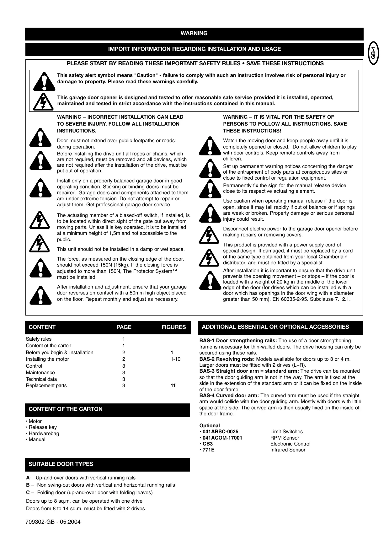
PLEASE START BY READING THESE IMPORTANT SAFETY RULES • SAVE THESE INSTRUCTIONS

This safety alert symbol means "Caution" - failure to comply with such an instruction involves risk of personal injury or damage to property. Please read these warnings carefully.

This garage door opener is designed and tested to offer reasonable safe service provided it is installed, operated, maintained and tested in strict accordance with the instructions contained in this manual.

WARNING - INCORRECT INSTALLATION CAN LEAD TO SEVERE INJURY. FOLLOW ALL INSTALLATION INSTRUCTIONS.
Door must not extend over public footpaths or roads during operation.
Before installing the drive unit all ropes or chains, which are not required, must be removed and all devices, which are not required after the installation of the drive, must be put out of operation.

Install only on a properly balanced garage door in good operating condition. Sticking or binding doors must be repaired. Garage doors and components attached to them are under extreme tension. Do not attempt to repair or adjust them. Get professional garage door service

The actuating member of a biased-off switch, if installed, is to be located within direct sight of the gate but away from moving parts. Unless it is key operated, it is to be installed at a minimum height of 1,5m and not accessible to the public.
This unit should not be installed in a damp or wet space.


The force, as measured on the closing edge of the door, should not exceed 150N (15kg). If the closing force is adjusted to more than 150N, The Protector System™ must be installed.

After installation and adjustment, ensure that your garage door reverses on contact with a 50mm high object placed on the floor. Repeat monthly and adjust as necessary.
WARNING - IT IS VITAL FOR THE SAFETY OF PERSONS TO FOLLOW ALL INSTRUCTIONS. SAVE THESE INSTRUCTIONS!

Watch the moving door and keep people away until it is completely opened or closed. Do not allow children to play with door controls. Keep remote controls away from children.

Set up permanent warning notices concerning the danger of the entrapment of body parts at conspicuous sites or close to fixed control or regulation equipment.
Permanently fix the sign for the manual release device close to its respective actuating element.

Use caution when operating manual release if the door is open, since it may fall rapidly if out of balance or if springs are weak or broken. Property damage or serious personal injury could result.

Disconnect electric power to the garage door opener before making repairs or removing covers.

This product is provided with a power supply cord of special design. If damaged, it must be replaced by a cord of the same type obtained from your local Chamberlain distributor, and must be fitted by a specialist.

After installation it is important to ensure that the drive unit prevents the opening movement – or stops – if the door is loaded with a weight of 20kg in the middle of the lower edge of the door (for drives which can be installed with a door which has openings in the door wing with a diameter greater than 50~mm ). EN 60335-2-95. Subclause 7.12.1.

| CONTENT | PAGE | FIGURES |
| Safety rules | 1 | |
| Content of the carton | 1 | |
| Before you begin & Installation | 2 | 1 |
| Installing the motor | 2 | 1-10 |
| Control | 3 | |
| Maintenance | 3 | |
| Technical data | 3 | |
| Replacement parts | 3 | 11 |
CONTENT OF THE CARTON
- Motor
- Release key
- Hardwarebag
- Manual
SUITABLE DOOR TYPES
A - Up-and-over doors with vertical running rails
B - Non swing-out doors with vertical and horizontal running rails
C - Folding door (up-and-over door with folding leaves)
Doors up to 8 sq.m. can be operated with one drive
Doors from 8 to 14 sq.m. must be fitted with 2 drives
ADDITIONAL ESSENTIAL OR OPTIONAL ACCESSORIES
BAS-1 Door strengthening rails: The use of a door strengthening frame is necessary for thin-walled doors. The drive housing can only be secured using these rails.
BAS-2 Revolving rods: Models available for doors up to 3 or 4m Larger doors must be fitted with 2 drives (L + R)
BAS-3 Straight door arm = standard arm: The drive can be mounted so that the door guiding arm is not in the way. The arm is fixed at the side in the extension of the standard arm or it can be fixed on the inside of the door frame.
BAS-4 Curved door arm: The curved arm must be used if the straight arm would collide with the door guiding arm. Mostly with doors with little space at the side. The curved arm is then usually fixed on the inside of the door frame.
Optional
041ABSC-0025
-041ACOM-17001
- CB3
771E
Limit Switches
RPM Sensor
Electronic Control
Infrared Sensor

INSTALLATION -
1
BEFORE YOU BEGIN
On the grounds of safety and to guarantee the perfect operation of the drive, the following points must be observed:
- The door must be suitable for automation. It must be particularly ensured that the door dimensions correspond with the technical properties in the specifications and that the door is suitably stable.
- Test the function capability of the door bearing and joining points.
- Ensure that the door does not have any wearing points. Clean running rails as necessary and lubricate them with silicone lubricant (not grease).
- Ensure that the door is correctly balanced.
- Remove the mechanical door locks in order to use the mechanical door locking system.
- A good earth connection must be available for connecting the drive.
The BAS drive can be installed in counterbalanced up-and-over doors of different designs. Some models are shown in Fig. 1:
a) Up-and-over door with single leaf.
b) Up-and-over door with folding leaf.
c) Up-and-over door with single leaf and ceiling running rails.
Do you have an access door in addition to the garage door? If not, the Outside Quick Release Accessory is required. This accessory allows manual operation of the garage door from outside in case of power failure.
CONNECTION OF ONE DRIVE
The motor is an a.c. motor operated by a capacitor which requires a special controller. The turning direction is determined by changing the polarity of the cables L-L on the controller. N is the PEN conductor (blue).
Cable cross-section: 0.75mm^2 or greater.
Voltage: 230 V AC
Do not use rigid copper wires. Do not lay low voltage cables in parallel.
CONNECTION OF TWO DRIVES
When connecting up two motors the procedure is the same in principle. The second motor does not have a limit switch and also has no controller. It is operated as the "twin" of the first motor and is wired into the controller like the first motor.
Cable cross-section: 0.75mm^2 or greater.
Voltage: 230 V AC
Do not use rigid copper wires. Do not lay low voltage cables in parallel.
INSTALLATION OF DOOR STRENGTHENING RAILS (OPTIONAL)
Door strengthening rails are to be used for thin-walled doors or doors which are not torsionally stiff.
The drive unit is heavy and a safe stable fixing is essential. The rails available as accessories can also be adjusted in height and permit simple fixing of the drive cover. Two strengthening rails are necessary if two drives are used on one door.
The door strengthening rails are normally fitted to the top of the door frame and attached to a bracing beam on the door at the lower end. The strengthening rails must be attached to the frame so that they are very stable.
It is not technically important whether the drive is seated in the middle of the door or not. It is normally fitted away from the middle of the door if the door handle or lock are in the way and are not to be removed. The drive reduces the height in the garage by about 10cm . In low garages an off-centre position is used so that higher vehicles can still be driven into the garage. Because of this longer revolving rods may be required at one side.
INSTALLATION OF THE DRIVE ON THE DOOR
The drive can be mounted on the door strengthening rails at the most varied heights.
You should observe the following points as early as possible:
- The revolving rods, which are to be mounted later and which are attached with a guide bearing to the door frame or in its vicinity, also require a stable mounting position. A stiffening beam on the door would be suitable for this.
- In the case of a single-rail (vertical) up-and-over door, the height of the revolving rods for the drive system should be – as in a typical installation - approx. 10cm below the end of the joint on which the door swivels or from which it is suspended. In the case of an up-and-over door with folding leaf the fulcrum point is approx. 10cm below the point at which it is folded. For a non swing-out double rail door the height of the door is halved.
- The height of the revolving rods also depends on the general height of the door. The telescopic door arm, which is to be fixed at the side later, may only be pulled out to a maximum of 80% of its reach (max. length 120~cm ). It is necessary to shorten the telescopic arm for small doors.
MOUNTING OF REVOLVING RODS (OPTIONAL)
The bearing (sheet metal angle) in which the revolving rods to the side of the door are guided, must be fixed extremely rigidly and must be lubricated with grease later after the installation has been completed. On the drive side the revolving rods are fitted with sleeves and are only pushed onto the drive. A small screw with an internal hex head in the sleeve secures the rod from slipping out.
It is strongly recommended that the side arms are first fixed before the revolving rods are cut to the required dimension.
INSTALLATION OF THE TELESCOPIC DOOR ARMS (OPTIONAL)
Whether the bent or straight telescopic door drive arms are used depends on the amount of space available at the side. Where the drive arm is attached to the frame depends on the door type and the amount of mounting space available. As close as possible to the point at which the door turns (swings) is ideal. This attachment should be welded to be as stable as possible since high forces are transferred to it.
- Straight telescopic arms operate alongside the door arms which turn the door (the arm which turns the door does not cross the path of the telescopic drive arm). There is sufficient space on the door frame to fix the drive arms to the side, top or bottom.
- Bent telescopic arms are fitted over the door arms which turn the door and are attached if insufficient space is available at the side to avoid contact.
Both types of telescopic arm may only be pulled out to 80% of their full path (max. length 120~cm ). In the case of small doors it may be necessary to shorten the telescopic arms.
The telescopic arms must be lubricated before assembly so that they function smoothly.
Once the side telescopic arms are mounted the exact length of the revolving rods can be established. On the telescopic arms are sleeves which are pushed into the revolving rods. If desired this connection can be secured by drilling through and using 10mm pins or a welded connection is also possible. The last option is by far the most secure connection.
ADJUSTMENT OF THE BALANCE OF THE DOOR
Following mechanical installation it is necessary to check whether the up-and-over door is still in equilibrium after increasing the weight of the drive and the accessories. If necessary counterweights or torsion springs should be used to regain equilibrium. Optimum swivelling is guaranteed if the door remains in the medium position (45^) and is in equilibrium with the drive unlatched. Furthermore it should be ensured, by manually moving the door, that when opening and closing it the swing takes place linearly and without any jumps or abrupt movements.

INSTALLATION OF DRIVE COVER
The drive cover is fixed at the side with 4 screws. Before positioning the drive cover the plastic thread inserts must be pushed into the door strengthening rails at the appropriate height. Before the cover is pushed on from the front, the screws should be given another turn.
EXCHANGING BULBS
Warning: Isolate drive from mains.
The plastic cover is screwed on at the side and after removing 2 screws on the left and 2 on the right it can be pulled downwards.
The transparent light cover underneath is fixed with 4 Phillips screws (PZ1) and after they have been removed it can be lifted off. The bulb is seated in a screw holder, type E14/25W.
Never use stronger bulbs. After exchanging the bulb reassembly takes place in the reverse order. Pay attention to the sealing fitting around the transparent light cover, which must be properly positioned.
Bulbs are not subject to guarantee claims.
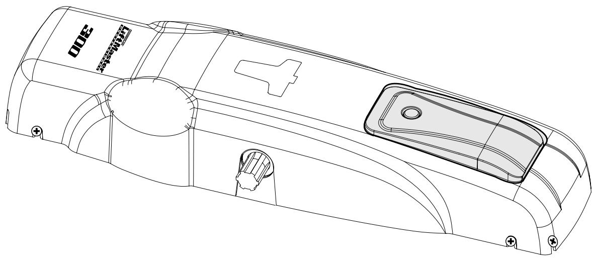
LATCH / UNLATCH DRIVE
If the drive is unlatched the door can be opened or closed by hand.. If the drive is locked the door can only be operated with the drive (Fig. 11).
Unlatching:
In a recess at the back of the plastic cover is an unlatching key. Take it out and push it into the marked opening which is also on the back of the drive. By turning it clockwise through about 180^ the drive is unlatched.
Latching:
With the unlatching key pushed in turn it clockwise until you feel a solid resistance. Then move the door a little by hand until you hear it click or you can establish that the door is latched again.
If 2 drives are mounted on the door both of them must be unlatched and latched.
If the garage has no external access it is necessary to mount an external unlatching system for the situation when the drive is without power.
CHECKS
Carry out a basic functional test on the drive and accessories. Hand over to the customer the page entitled "User Information", demonstrate the proper operation and use of the drive as well as showing them any potential hazards.
MAINTENANCE
The following steps should be carried out at least every 6 months:
- Checking the regulation of the motor torque.
- Check the rollers and guide rails on the door. Carry out cleaning and lubrication as necessary.
- Functional check of the interlock release system.
- Functional check of the safety equipment.
REPAIRS
The authorized Service Centres are responsible for repair work.
TECHNICAL DATA
Model BAS300
Supply voltage 230Volt
Frequency 50Hz
Nominal power 250W
Max. power 400W
Max. torque 350Nm
Capacitor 10uF
Thermal protection 140^
Motor speed 1400 rpm
Temperature -20 to +55^
Operating frequency, cycles/hr 20
Weight approx. 9kg Type of protection IP44
Max. door width (m), 1 motor 3
Max. door height (m), 1 motor 3
Max. door area (m^2) , 1 motor 8
Max. door width (m), 2 motors 5
Max. door height (m), 2 motors 3
Max. door area (^2) , 2 motor 14
Declaration of Conformity
The undersigned, hereby declare that the equipment specified, and all accessories, conforms to the Directives and Standards stated.
Model: .BAS300
EN55014, EN61000-3, EN61000-4, ETS 300 683, EN 300 220-3, EN60335-1, and EN60335-2-95
√ 89/336/EEC
73/23/EEC
1999/5/EC
Declaration of Incorporation
A power door operator, in combination with a door must be installed and maintained according to all the Manufacturer's instructions, to meet the provisions of Machinery Directive, 89/392/EEC.
B.P.Kelkhoff
Manager, Regulatory Affairs
THE CHAMBERLAIN GROUP, INC.
Elmhurst, IL 60126
USA
November, 2003

Babba P. Keckhoo
Barbara P. Kelkhoff
Manager, Reg. Affairs
INDICACIONES IMPORTANTES PARA EL MONTAJE Y USO
√ 89/336/EEC
73/23/EEC
√1999/5/EC
Manager, Regulatory Affairs
THE CHAMBERLAIN GROUP, IN
Elmhurst, IL 60126
USA
September, 2003

Babara P.Ketkhoft
Barbara P. Kelkhoff
anager, Reg. Affairs
ISTRUZIONI IMPORTANTI PER IL MONTAGGIO E L'USO

PER PRIMA COSA LEGGERE QUESTE IMPORTANTI NORME DI SICUREZZA!

√89/336/EEC
73/23/EEC
1999/5/EC
Manager, Reg. Affairs
√ 89/336/EEC
73/23/EEC
1999/5/EC
Inbouwverklaring
Barbara P. Kelkhoff Manager, Reg. Affairs
INSTRUÇÉS IMPORTANTES DE MONTAGEM E UTILIZAZão

89/336/EEC
73/23/EEC
√1999/5/EC
Manager, Regulatory Affairs
THE CHAMBERLAIN GROUP, INC.
Elmhurst, IL 60126
USA
September, 2003

Babana P. Keelkhoft
Barbara P. Kelkhoff
Manager, Reg. Affairs
LiftMaster ™
PROFESSIONAL
BAS300

Für Service: (49) 6838/907-172

Pour Service: 03-87-98-15-93

For Service: (+44) 0845-602-4285